driving motors
individual assignment: add an output device to a microcontroller board you’ve designed, and program it to do something
group assignment: measure the power consumption of an output device
In order to make progress on my final project, I’m going to make a circuit that will allow me to control a motor that Dan has given me: T-Motor F80 KV2500 High-Performance Brushless Electric Motor for Multi-Rotor Aircraft.
The motor is rated to be KV2500 which means that the motor will turn 2500 times (there will be 2500 revolutions) per minute when 1V (one Volt) is applied with no load attached to the motor.
Detailed information about the motor can be found at this link Learning about brushless DC motors. More about how a brushless DC motor works brushed dc motors versus brushless motors
control brushless motor using arduino tutorial 3/5 stars
digikey how to control and power a brushless motor
- BLDC motor driver power MOSFET chips more
The speed of the brushless motor is varied by adjusting the timing of pulses of current delivered to the several windings of the motor. previous student using brushless motor… not that helpful tbh.
Taking a look at the output devices syllabus here are a few things to dive deeper into: brushless DC motor (BLDC) efficiency, density, reliability, noise inrunner, outrunner, pancake, fan Kv (RPM/V) ~1,10,100 A,$ triple half-bridge A4941, A4963 drive waveform open-loop, closed-loop control back EMF (BEMF) sensing electronic speed controller (ESC) firmware servo PWM initialization, calibration LiPo batteries charge controller
motor control Allegro TI Trinamic Pololu TinyG RAMPS Mechaduino nRF52
Materials
- $32 YEP 60A 2-6s Electronic Speed Controller
- $27 T-Motor F80 KV2500 High-Performance Brushless Electric Motor for Multi-Rotor Aircraft.
Some details about the ESC provided by fab lab:
- Max Cont Current: 60A
- Max Burst Current: 80A for 10 seconds
- Input Voltage: 2-6 cells li-XX or 6-16 Ni-MH/Ni-Cd battery
- BEC: 5.5V/6A Switching BEC
- PWM: 8~16 KHz
- Max RPM: 240,000rpm for 2 Poles Brushless Motor
- PCB Size: 50x32x12mm
- Weight: 63g (including wires)
2 youtube tutorials on programming the ESC 1,2
Some details about the motor:
- Shaft Diameter: 4mm;
- Stator(Dia. x Len):-+ 23mm x 8mm;
- Motor Dimensions(Dia. x Len) 28.8x33.5mm;
- Motor Weight (Incl. Cables) 43.1g
- Efficiency: Idle Carrent @10v: 1.9A;
- Internal resistance: 21 milliohms
- Power Ratio =50+;
- No. of Cells (Lipo): 2-4S
From the motor’s specs and test data, I can see that the current ranges from 14.59 A to 49.63 A and 15.5V or 14 V work.
Notes http://ww1.microchip.com/downloads/en/DeviceDoc/Atmel-2586-AVR-8-bit-Microcontroller-ATtiny25-ATtiny45-ATtiny85_Datasheet.pdf
- page 61; OC1B: Inverted Output Compare Match output: The PB3 pin can serve as an external output for the Timer/Counter1 Compare Match B when configured as an output (DDB3 set). The OC1B pin is also the inverted output pin for the PWM mode timer function
- page 71: section 11.7 modes of operation 11.7.3 talks about fast PWM mode
- page 85: “In PWM mode, OCR1A and OCR1B provide the data values against which the Timer Counter value is compared. Upon compare match the PWM outputs (OC1A, OC1A, OC1B, OC1B) are generated. In PWM mode, the Timer Counter counts up to the value specified in the output compare register OCR1C and starts again from $00. This feature allows limiting the counter “full” value to a specified value, lower than $FF. Together with the many prescaler options, flexible PWM frequency selection is provided. Table 12-3 on page 88 lists clock selection and OCR1C values to obtain PWM frequencies from 20 kHz to 250 kHz in 10 kHz steps and from 250 kHz to 500 kHz in 50 kHz steps. Higher PWM frequencies can be obtained at the expense of resolution”
- reading section 11… what is an output compare register?
- section 11.6 says: “The Compare Output mode (COM0x[1:0]) bits have two functions. The Waveform Generator uses the COM0x[1:0] bits for defining the Output Compare (OC0x) state at the next Compare Match. Also, the COM0x[1:0] bits control the OC0x pin output source.” “The Data Direction Register bit for the OC0x pin (DDR_OC0x) must be set as output before the OC0x value is visible on the pin”
Process
- find pin on ATTiny45 that can do PWM: PB4. This pin will be connected to ESC, which will receive the PWM output.
- how do I turn on PWM mode for PB4?
- the motor will be connected not to the ATTiny, but to the ESC which will also be the source of power for the motor.
Questions
- Should my Timer/Counter be clocked internally or by an external clock source on the T0 pin, given that I will be ouputting pwm to the ESC? What does this decision depend on?
- “The Timer/Counter is inactive when no clock source is selected” (pg 66); how do i select the clock source? answer is in section 11.3 “Clock Select (c) bits located in the Timer/Counter0 Control Register (TCCR0B).””
- Do we have a programming card for the YEP speed controller
Meeting w/ Kreg
- I need to figure out how much power to supply to the ESC
- I need to figure out how much power i should supply to the ATTiny
- If I want to make my own “arduino” board, I will want to expose the pins using male headers (so that i can use female to female jumper wires to connect modules)
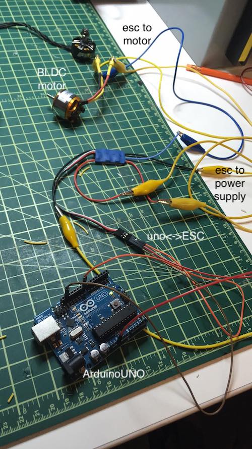
I can break up my work into two components: 1) make a general purpose microcontroller board that can interface with various parts 2) get an esc hooked up to a motor and get that working. 3) connect my microcontroller board to the brushless motor module.
BLDC MOTOR + ARDUINO UNO
Since this week is about output devices, I’d like to attempt to get started with getting the motor working–even if with an Arduino Uno first.
EDIT: in the lab, I found a different ESC that easily plugs into a brushless motor. Materials:
- $16 Brushless motor: BL-2212/13 more specs
- Based on the additional specs, it looks like it’s safe to run the motor w/ current in the range 9.2A - 14.6A and voltage in the range 7.3V - 12.3V.
- With an APC 11x5.5 E propellor: 7.6V, 9.2A 18oz of thrust, and 70W of power with .26oz/W thrus efficiency.
- $12 Volantex RC Easy-plug 30-Amp Brushless ESC 2-4S LiPo 5-12 NiCd/NiMh EP-30 RoHS
- to understand what voltage to supply to the ESC, I need to understand the battery specs (LiPo vs NiCd):
- “A LiPo cell has a nominal voltage of 3.7V. For the 7.4V battery above, that means that there are two cells in series (which means the voltage gets added together). This is sometimes why you will hear people talk about a “2S” battery pack - it means that there are 2 cells in Series. So a two-cell (2S) pack is 7.4V, a three-cell (3S) pack is 11.1V, and so on.”, so a 2-4S LiPo corresponds to 14.8 V.
- to understand what voltage to supply to the ESC, I need to understand the battery specs (LiPo vs NiCd):
https://www.instructables.com/id/Control-Brushless-Motor-Using-Arduino/ ^ supplies code that uses the Arduino Servo library
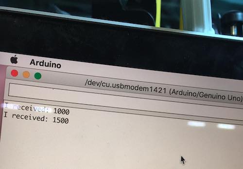
using serial input as input for controlling the motor output
In order to convert the string serial input to integer, I looked up C & C++ libraries for doing that. Found this tutorial but got the following error upon attempting to include the libraries:
  /Users/quacht/Documents/Arduino/brushlessmotor/brushlessmotor.ino:2:20: fatal error: iostream: No such file or directory
   #include <iostream>
                      ^
  compilation terminated.
  exit status 1
  Error compiling for board Arduino/Genuino Uno.
Turns out “Some of the libraries you mention (iomanip, iostream, queue, string) are part of the STL - Standard Template Library. Whilst it does not ship with the IDE download, you can install it yourself.” (StackExchange)
more info on the arduino servo library, since I’m using that to control to esc pwm with arduino, without the servo library
my code:
  #include<Servo.h> //Using servo library to control ESC

  Servo esc; //Creating a servo class with name as esc
  String serialInput = "";
  const int buttonPin = 2;     // the number of the pushbutton pin
  const int ledPin =  13;      // the number of the LED pin
  int buttonState = 0;         // variable for reading the pushbutton status

  void setup()
  {
  // initialize the LED pin as an output:
  pinMode(ledPin, OUTPUT);
  // initialize the pushbutton pin as an input:
  pinMode(buttonPin, INPUT);

  esc.attach(9); //Specify the esc signal pin, Here as D8
  esc.writeMicroseconds(1000); //initialize the signal to 1000
  Serial.begin(9600);
  }

  void loop()
  {
  // read the state of the pushbutton value:
  buttonState = digitalRead(buttonPin);

  // check if the pushbutton is pressed.
  // if it is, the buttonState is HIGH:
  if (buttonState == HIGH) {
    // turn LED on:
    digitalWrite(ledPin, HIGH);
    esc.writeMicroseconds(1010);
  }
  else {
    // turn LED off:
    esc.writeMicroseconds(1000);
    digitalWrite(ledPin, LOW);
  }
  //
  //  // send data only when you receive data:
  //  if (Serial.available() > 0) {
  //          // read the incoming string:
  //          serialInput = Serial.readString();
  //
  //          // say what you got:
  //          Serial.print("I received: ");
  //          Serial.print(serialInput);
  //
  //          esc.writeMicroseconds(serialInput.toInt());
  //  }

  }
In following the Instructables tutorial, I ran into trouble because the pin number in the given example code was wrong (didn’t correspond to the diagram provided in the instructable). I was also learning how to use the power supply in order to supply the right voltage and current. I fried my first ESC because I had allowed the current and voltage to jump up to 32V and about 2 or 3 Amperes.
With help from Yanni, I was able to have safer practices…
Me:
I'm trying to figure out what Voltage to supply to my ESC
and they only specify the battery
so i read this
https://rogershobbycenter.com/lipoguide/
which says  So a two-cell (2S) pack is 7.4V, a three-cell (3S) pack is 11.1V, and so on
"Working Voltage: 2-4S LiPo or 5-12 cell NiCd/NiMh" --> means 2s or 4s lipo corresponding to 7.4-14.8 V since each S is around 3.7 V each.
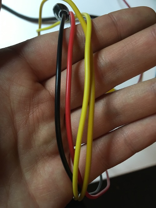
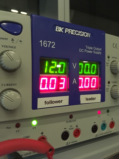
I use alligator clips to provide power to the ESC. I make sure the alligator clips are large enough to handle the current.
Me:
halp
so
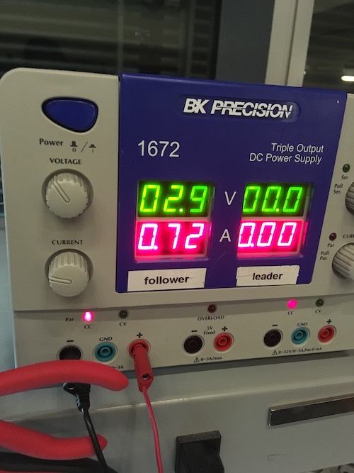
i was turning the nob
and i turned it all the way for V
and it was only at ike 3V
so i turned up the A
and it went to ~2.9-3 A (its max)
but V maxed out at ~6.5 ish
untill i heard a click
and
it switched from CC (red light) to CV green light or something
and then it was at 32 V
and i was confused
so i turned down the knob
Yanni:
you need to set the voltage when its disconnected. then u turn up the current slowly.
Me:
what about
turning up the voltage
is there an order between the two
Yanni:
u shdnt turn up the voltage.
Me:
but its at 0
Yanni:
because theres not enough current, turn up the current and the voltage will go up too
Me:
i turn up current. it doesnt go up
Yanni:
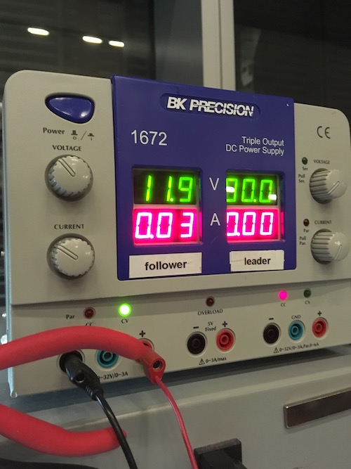
disconnect; set v to 12; set i to 0
Me:

Me: 12 at .03A
Making my own microcontroller board using ATMEGA16U2
Interesting Links: building your own custom teensy past student blog
Parts: 10K ohm resistor 100 nanoF ceramic and 1microF ceramic (to take the place of 10microF electrolytic) in parallel
Some notes from Kreg
ATMega command to set the period of the hardware pwm OR if I wanna go Neil’s way, I can check out the bit-banging method seen in rgb led pwm code (output devices week). atmega hardware pwm avr c library servo control wikipedia 1500 = should stop motor 1000 = full speed counterclockwise 2000 = full speed clockwise anything besides 1500 and going farther controls speed of rotation.
driven the same way as a continuous servo motor.
“how long is the on pulse” –> determine position
Tips:
- I can use an Arduino pinout to have a nice visual representation of what pins on the ATMega do what.
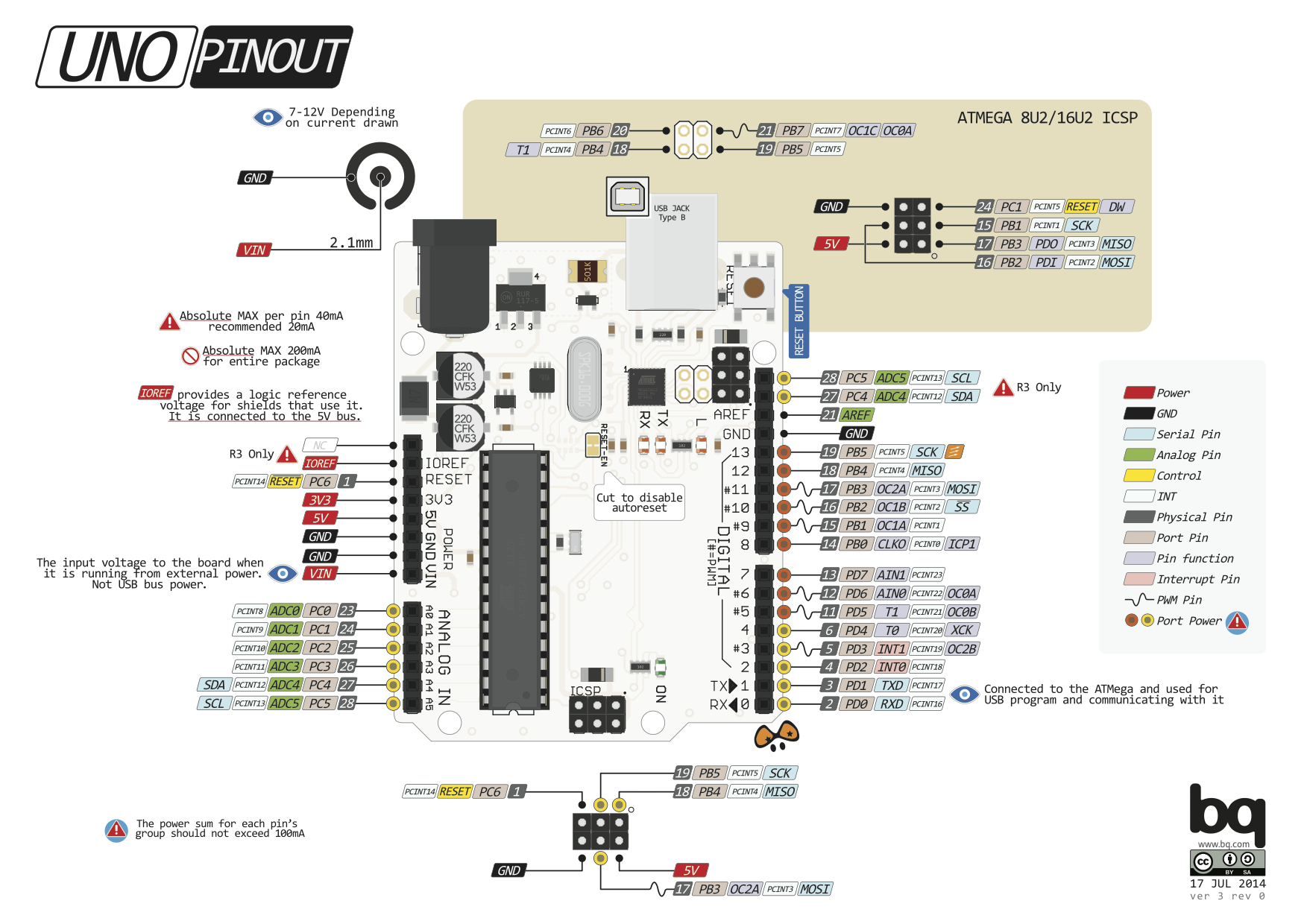
Programming the AVR to use PWM
This tutorial is pretty useful. Waveform Generation Mode Bit Description