Week 2: Electronics Production
Introduction
This week, I learned how to work on electronics production. Specifically, there were three parts to this assignment: first, milling a PCB; second, soldering the circuit and ICs onto the PCB; and lastly, installing software onto the PCB.
- Software used: Avrdude
PCB Milling
Given that we had a already made image for the PCB design, we had to run two cuts for the PCB in the Roland, the first using a 1⁄64 pointer for tracing, and the second using the 1⁄32 pointer for the outline and cut.
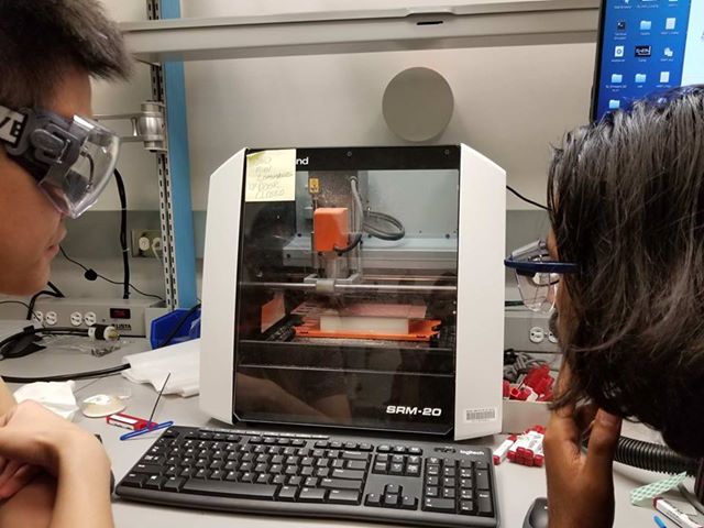
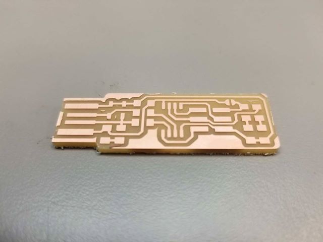
After running the machine (which takes a while), here is the finished product!
Soldering & Programming
Next, I had to solder the components for the PCB onto the board. First, I gathered the equipment:
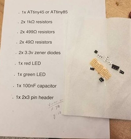
The soldering process took a while as our components were quite small. After half an hour or so, I finally finished!
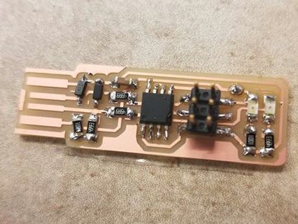
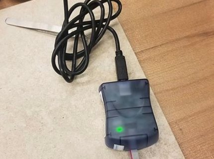
Finally, in order to program the board, I used a programmer board to connect to the 6 pins of the board, while using another USB port to connect to the board for power. Fortunately for me, the programming part went very smooth, as I didn’t need to debug my software or hardware. Overall, it was a fun experience!
Tips for the future
- Use double sided tape to keep track of where your small components are.
- Check which resistor you are using by actually looking on the resistor itself. I had to un-solder two resistors as I ended up choosing the wrong ones.
- A lot of soldering techniques that I’ve learned in person
- When running
make flashandmake fuses, at first my compilation failed. Addingsudosolved the problem for me.
Assignments
- Make an in-circuit programmer by milling the PCB
- Solder components onto the PCB
- check if the PCB can be programmable, and do so
- refer to Ben’s documentation of the assignment link