Week 9: Inputs
Note: This inputs week project is superceded by my final project, which involves extensive communication with an infrared camera.
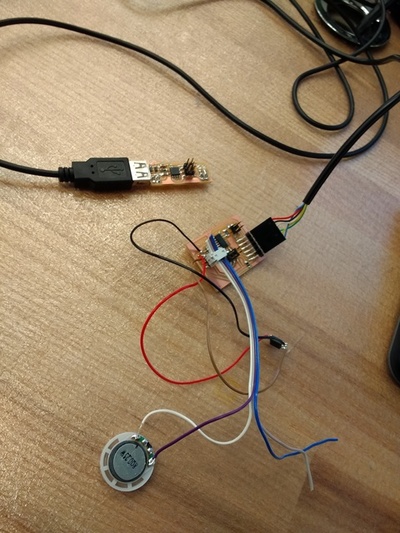
This week I wanted to augment a speaker board with a step-response touch sensor. This is a learning exercise to see whether I can make a device that plays different notes depending on how much pressure is applied to a conductive pad.
I learned the following:
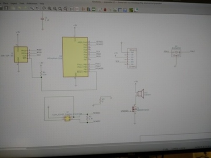
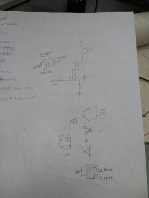
- Anything that draws a large current should be insulated from the microcontroller ciruit to avoid damaging it. You can insulate the microcontroller by connecting it to the speaker by way of a mosfet. The mosfet acts like a switch controlling the link between ground and high voltage that the speaker is on (see diagram). Depending on whether the gate is presented with high or low voltage, the link is turned on or off.
- I built the circuit as follows, using KiCad software. I exported as
SVG and converted the script to png using my ImageMagick scripts
developed way back when we were first designing circuits.
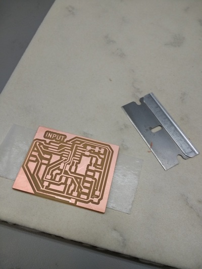
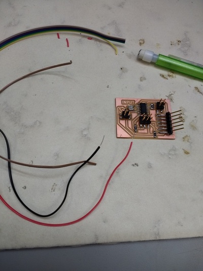
- Sometimes milled circuits can be a little rough, with tiny copper
burrs along the edges. Even without bridging connections, these
burrs can be undesirable. Burrs can be removed by gently scraping
the broad edge of a razor against the top surface of the board (as
if sweeping).
- I mistakenly selected the wrong footprint for the mosfet (needed to
double-check against the fab inventory and the exact contents of
our lab, as well as distinguish between N- and P-type
transistors). As a result, I had to learn the technique of
"deadbugging", where you solder wires to your component and solder
the wires to the pad; the effect is that the correct component is
electrically connected to your circuit, free-floating on wires.
- You have to be rather careful with the mosfet, as it has three very
different ports — gate, source, and drain. Only by looking at the
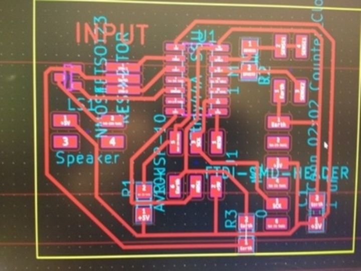
datasheet can you tell which is which. I took very careful notes
showing how the schematic for my circuit lined up with the pcb
board layout for my circuit and how the abstract symbol for a
transistor lined up with the physical embodiment of the transistor.
- I made my own four-pin ribbon cable by clamping a vice around a four-pin connector that had four wires threaded to it. The connector is initially spread open, which allows you to see (and carefully document!) which colored wires will go to which of the four ports. This information is essential for determining the correct orientation of the header, and also especially because only two of the four wires are actually live for the speaker. (This is probably a design flaw in the circuit; for convenience, I should instead bridge the four pin connector so there are two high and two low pins.)
- Having assembled the circuit, I am still debugging it — it has an RC=-1 error, which suggests bridged connections somewhere, as all of the software and programmer components seem to be working fine. I'll need more time with the multimeter to find out.