Virtual reality through IR headtracking
Table of Contents
Note: This supercedes my previous project report.
Inspiration: https://youtu.be/Jd3-eiid-Uw?t=149
TED talk: https://youtu.be/QgKCrGvShZs?t=19
1 What is it?
I propose building a USB device that tracks the position and orientation of a single user's head, and uses that information to furnish a realistic view-dependent rendering of a 3D scene.
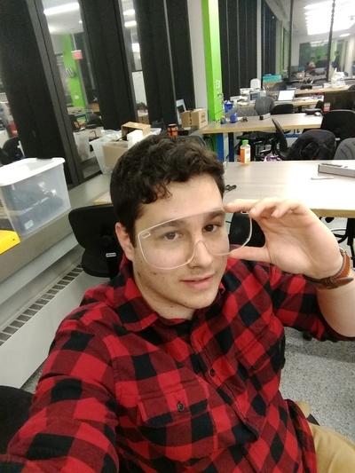
The device consists of a USB infrared camera rig (a webcam-sized component which clips to the top of a computer monitor and communicates with the computer over USB) and an infrared emitter device that affixes to the user's head (default option: safety glasses equipped with battery-powered infrared LEDs.)
The firmware on the camera rig detects and pinpoints the LED light sources using the infrared camera. It collects that information over
2 Who's done what beforehand?
The video shown above is the foundational example. Using the Wii remote and sensor bar from a Nintendo Wii, the author hacked together a device that performs head tracking in this way. Since this result, a community of other hackers have put together Wii-based hacks of various kinds.
An advantage of using Nintendo products is that they are easily attainable and cost potentially less than their individual parts due to various economic factors.
A primary defect, explored here, is that the parts are pre-assembled and blackboxed. We shouldn't have to buy the equipment from Nintendo itself. I also suspect they are also no longer as inexpensive as their constituent parts.
3 To-do list
[X]DONE Source materials.
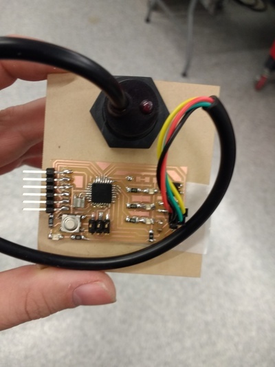
[X]Infrared camera. The most special-purpose part is the infrared camera, which I have ordered from Digikey. https://www.digikey.com/catalog/en/partgroup/ir-positioning-camera-for-arduino/71049 It performs some on-board image processing, which is neat, but time permitting I intend to investigate the inner workings to build one myself if I can.[X]Programming cables. It is useful to have a set of cables for connecting boards to computers and each other in various ways. I have obtained a male-female USB extender, an FTDI serial-to-usb cable, and I have built several 2x03 and 2x02 ribbon cable connectors.
[X]DONE Set up a server. Communication will be handled in Javascript using nodejs, so as to take advantage of both the 3D graphics capabilities and the serial communication.
[X]Install nodejs and npm.[X]Design a simple nodejs+websockets demo. (Completed during interfaces week.)[X]Communicate over serial using nodejs (Completed during interfaces week.)[X]Install i2c for nodejs.As a result of experimentation during interfaces week, I have adopted a new approach: I will use nodejs to communicate with the board over serial, and the board itself will communicate over I2C. Node never needs to speak I2C.[X]TODO Use nodejs to communicate with a basic I2C node board.
[X]Master I2C communication.
[X]Mill and stuff an I2C bus board. (Neil's example board will work).I broke the proverbial lance on this during network week, and will therefore instead try prototyping with an atmega with built-in I2C capabilities rather than bitbanging.[X]Design and build a mega board for speaking I2C.[X]Test the mega board.[X]Install infrared lights on the mega board…[X]…and verify that they work.[X]Communicate over I2C. The infrared camera itself transmits its information over I2C.
[X]Set up a digital environment
[X]Render a digital scene[X]Make a mockup of camera input, controlled by the mouse instead of by infrared light positioning.
[ ]Design and build an enclosure for the camera rig
[ ]Experiment with ways of combining the milling board with, e.g. a binder clip.[ ]Try interference fit with an acrylic box enclosure.[ ]Design the box, with a hole for serial cable and for the camera.
[-]Build an infrared emitter
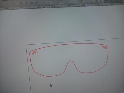
[X]Place infrared LEDs on a regular board.[X]Ensure that the ir camera can detect them. (Todo during networking week)[ ]Try prototyping an acrylic bar or other simple-to-cut device that you can affix a battery to.[X]Instead, first mill a PCB board that supports a battery[ ]Design parametric glasses using SVG generation.[ ]Design a cancellated visor that has holes for through-hole infrared leds.[ ]Experiment with ways to attach arms to the visor (3d printed hinges? interference fit between acrylic–brittle?)[ ]Experiment with ways of attaching circuitry to the glasses (copper tape, vinyl cutter, etc.) May need to sandwich electronics between two support structures for aesthetics.[ ]Perform an initial draft test.[ ]etc.
[-]Coordinate Projection
[X]Transform 2d infrared coordinates into 3D world coordinates.[ ]Figure out a good user interface for calibrating the origin of the camera (simple reset switch on emitter? keyboard input?)
[ ]Design an enclosure tailor-made for the pcb board and camera
[ ]screws
[-]Integration
[X]Ensure that nodejs can communicate with a basic serial board. (Finished during interfaces week.)[X]Ensure that position data can be transmitted over web sockets. (Finished synthetic data generation project during networking week: the nodejs server artifically generates position data and sends it over websockets, where it's interpreted and plotted client-side.)[X]Understand the format being transmitted by the IR camera. (Read on the datasheet, but to be confirmed in practice.)[ ]! Experiment with possible speedups — to get best speed, should I convert highly compressed ir camera data in C before sending over serial, or server-side in javascript before sending it over websockets, or client-side in javascript in the browser?[X]Translate the IR camera data into virtual-world viewpoint given the known rigid arrangement of the led array.[ ]Decide what to do with bad data.[ ]Unknown unknowns.
[ ]Stretch goals
[ ]Binocular ir cameras for additional dimensions of movement.[ ]Experiment with more than two leds, including a tetrahedral arrangement for head rotation.[ ]Keyboard controlled walking[ ]Multiple user agents through shuttering.
4 Work log
Built a board for speaking TWI/I2C by bitbanging. Used Neil's serial bus board and adapted code from the accelerometer. Board failed in mysterious ways (see networking week); decided to revisit using native TWI.
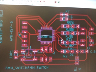
Designed a board for natively speaking TWI (using atmega328p).
- Board design
- Board had some manufacturing and design errors.
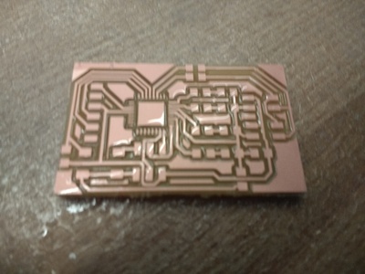
- Manufacturing errors: some pins were subtly bridged (RESET and CLK).
- Design errors: accidentally used pins that were not general-purpose I/O for some of the LEDs (most ADC pins are, but these weren't). Put placeholder 0 ohm resistors on the SCL and SDA lines, forgetting that if I needed pullup resistors, they'd need to be between the lines and Vcc, not on the lines themselves.
- Mysteriously, serial i/o produces gibberish. Will need to use oscilloscope to determine
- ! Emergent idea: Although I initially intended the LEDs to indicate status, I could also use one as an IR LED for testing the camera.
- Board design
Programmed the board.
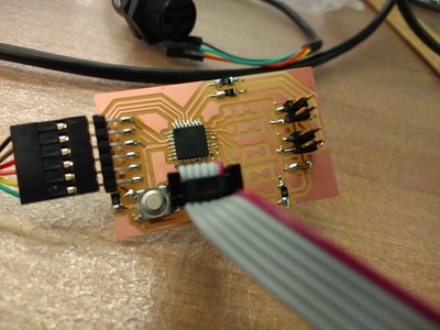
- I used Neil's hello.arduino.328p.blink code to test whether the board was programmable at all.
- I borrowed a TWI library to test whether I could communicate with the camera. I intend to define my own API functions instead.
- Initiating TWI worked once I fixed the solder bridge between reset and clk (which caused the board to reset every time the register was activated).
- Sending a hello command to the camera worked — after many hours of debugging, I discovered that it was necessary to wait around 1sec before sending the first TWI command. I suspect the camera needs time to load.
- Sending a read request to the camera worked — after a great mystery (the camera itself has very sparse, contradictory, flawed documentation written by various hobbyists), I found that you have to write a specific byte to the camera each time you want to request bytes from it.
Fixed serial (Thursday)
- I swapped which of TX and RX refered to in and out again. For reference, it's relative to the computer: Transmit is out, and Recieve is in. (To be absolutely sure, compare the board design and code for echo hello world and see which is which.)
- Adapting the echo hello world code from attiny45 produced gibberish, suggesting timing errors.
- I realized that the makefile for m328p.blink assumed a 20MHz
crystal on the mega. So I changed
F_CPUfrom 20000000 to 8000000, as 8MHz is the default clock speed for the m328p's internal clock. - Finally, the default echo hello world baud rate was too high. Given that there's no crystal, we need a lower baud rate.
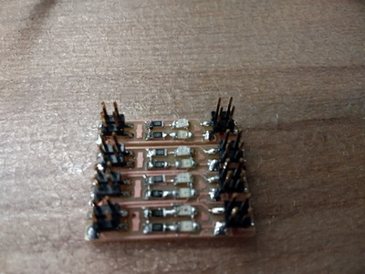
LED daughter boards
- Using inkscape, made a triangular array.
- Then experimented with a simpler design. You can add one or two leds (so, for example, one infrared and one visible).
Board 2.0
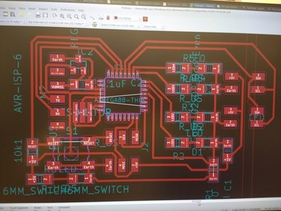
- Comparison:
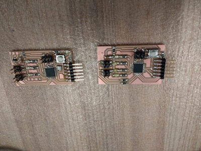
- Relocated all four LEDs to general i/o pins.
- Added a status LED between vcc and gnd.
- Added a 5V regulator to regulate power to the peripherals. This required one additional 0.1uF capacitor, because the datasheet recommended adding smoothing capacitors to both sides. (I already had a smoothing 1uF capacitor between unregulated power and ground, because this design is a descendant of one of Neil's.)
- Added a 20MHz resonator — I expect the camera might require fast timing. Will remove if unneeded.
Saturday 8/Dec/2018
Having milled four led daughter boards, stuffed them.
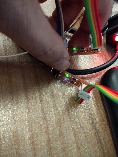
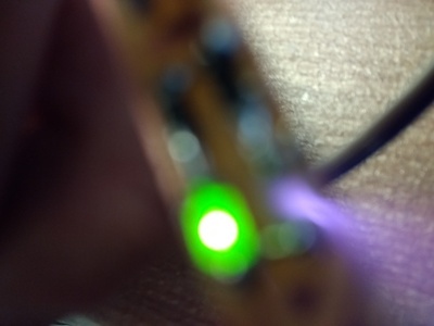
Used phone camera to check that the infrared leds were working. Turns out they work with 100Ω resistors rather than 500Ω resistors.
Finally found documentation for the commands to send to the camera to make it activate. It works! (Todo later: simplify the code using subroutines and fundamental register commands instead of library commands.)
By inserting appropriate delays, became able to request repeated reads from the camera without it blocking.
Used Interface week's nodejs code to read from the serial output
Wrote a bit-shifter to unpack the encoded data from the camera.
Modified my synthetic-data-generating code to decode serial input and send it over web sockets (modification of Interface week's nodejs code.)
! Plotting of a single point works correctly. (Todo: test multiple points.)
Plotting of multiple points works correctly. Experimented with various ways to deal with the event-based serial data spurts. Optimization using
sliceinstead of repeatedshift.Workflow:
- Run node on
ir-serial.js - Open a page like
dxh.plot.infrared.htmlin the browser.
- Run node on
wooden glasses (all one piece with flextured hinges!)
https://www.youtube.com/watch?v=2Nj167idFkQ
- Hinged all-wood glasses https://www.instructables.com/id/Laser-cut-foldable-wooden-glasses/
Sunday 9/Dec/2018
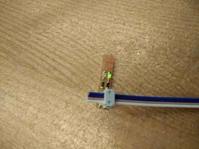
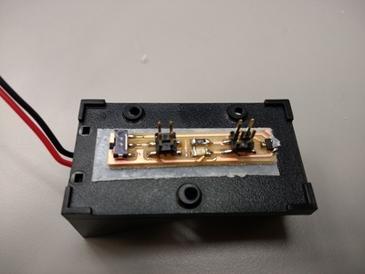
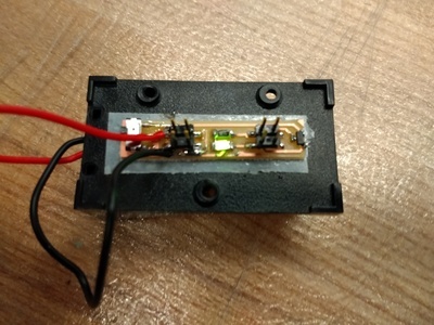
- Made a daughter board for converting 9V battery into regulated 5V using four pin connectors.
- Worked out projection math successfully (field of view calculations; camera coordinates to real coordinates)

Monday 10/Dec/2018
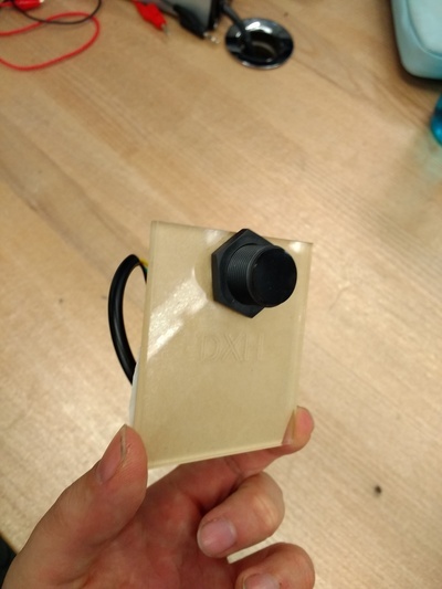
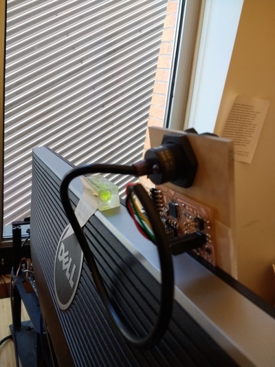
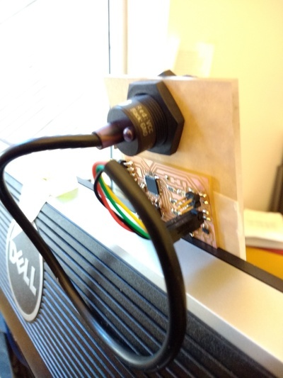
- Began designing enclosure for pcb board; sketched plan to print a back part and lasercut a viewing screen.
- Brainstorming about ways to affix board to monitor like webcam.
- Lasercut a mounting place for the pcb board
Tuesday 11/Dec/2018
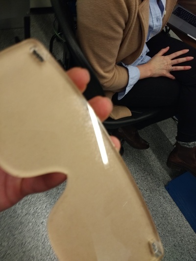
- Designed and lasercut draft version of visor; further iteration awaits.