Infrared head-tracker
Table of Contents
1 Demonstration
(Watch especially the corners of the screen where new parts of the scene come into view as you approach.)
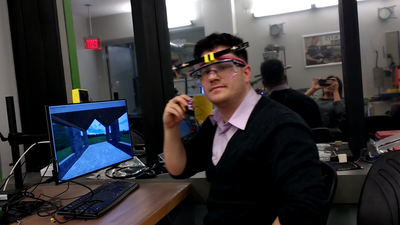
With this project, I convert a computer monitor into a window into a virtual world: a user who looks at the monitor from different angles, or who approaches the monitor, can see more or less of the 3D scene — exactly as with a real window.
Here's how the monitor looks without the infrared tracking (it's just a monitor):
And here's the same scene with infrared tracking. Note the immersive effect as you approach:
At a high level, the project consists of two devices: an infrared camera rig (a webcam-sized component which is fixtured to the monitor and plugged into the computer over usb) and an infrared emitter device. The infrared emitter device is worn by a single user; by detecting the position of two infrared dots, the camera can determine where, and how far away, the user is. (The camera rig does all of the computation; the emitter simply has lights.)
2 What else exists
Wiimote-based headtracking was the initial inspiration for this approach, and in fact it works on the same principle. The Nintendo Wii gaming console ships with a Wii remote (which is equipped with an accelerometer and an infrared camera, and which communicates over bluetooth) and a "sensor bar" (which actually just contains infrared LEDs). Since Johnny Lee's initial demo, a community of other hackers have put together Wii-based hacks of various kinds.
Inspiration: https://youtu.be/Jd3-eiid-Uw?t=149
TED talk: https://youtu.be/QgKCrGvShZs?t=19
An advantage of using Nintendo products is that they are easily attainable and cost potentially less than their individual parts due to various economic factors.
A primary defect of using Nintendo products, which I've circumvented with my project, is that the parts are pre-assembled and blackboxed. We shouldn't have to buy the equipment from Nintendo itself. I also suspect that nowadays, these Nintendo products are also no longer as inexpensive as their constituent parts.
Accelerometer-based headtracking is another popular approach.
Virtual reality headsets are sort of the opposite of what I've done. These place you into a virtual environment, whereas I place a virtual window into the real world. It's closer to a kind of augmented reality, though without special glasses (You just wear a pair of LEDs; the form factor could be made, I imagine, even slimmer than I've gotten it.)
3 What I built
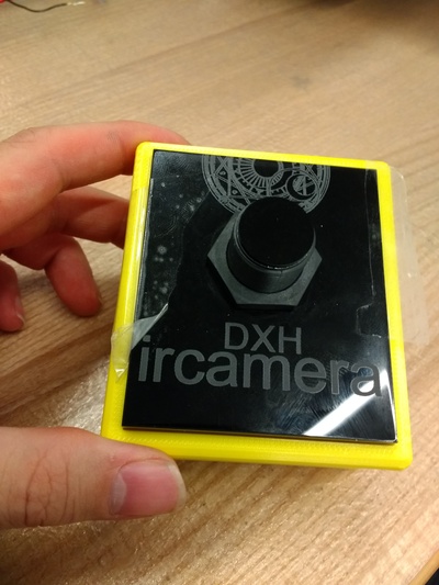
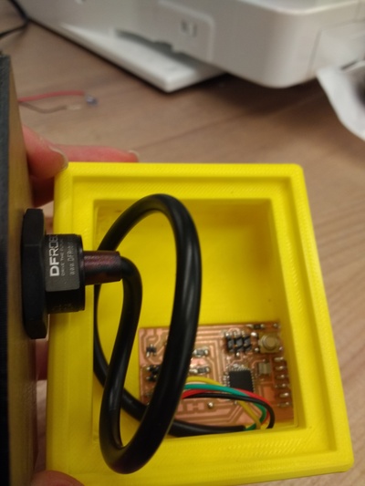
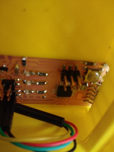
- I designed a camera rig, consisting of a board for communicating over serial (with a computer) and over I2C (with a camera). The camera rig is enclosed in a 3D printed case and sealed with a decorative lasercut lid.
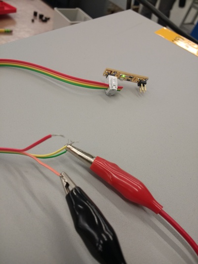
I designed several neat modular boards, including a regulated 5V power supply (battery case affixed to a 5V regulator) and infrared LED daughter boards with through-hole LEDS affixed using rivets. They have various neat features such as all sharing asymmetric (never reversible) four pin headers for vcc and ground, having LED status lights, and being arrangeable in arbitrary topologies.
I assembled the neat modular boards into an emitter rig, which consists of two daughter boards and the regulated 5V power supply. They were enclosed in a laser-cut enclosure and affixed to a headband with 3D printed joints.
The author demonstrates the assembled device:
Earlier incarnations:
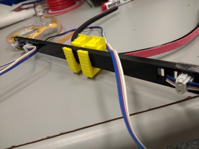
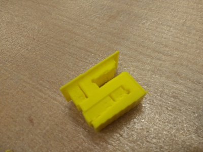
The 3D printed joints took me on a detour into the design of effective pressure-fit clips, similar to work on joinery out of wood. The clips are designed to be pretty structurally robust.
I used all free (libre) software to do so:
- I programmed in C, using emacs as a development environment.
- I used KiCad to design circuits.
- I used OpenScad to design all 3D printed objects.
- I used Inkscape to draw all lasercut objects.
4 Materials
The most expensive item was the infrared camera, a specialty device costing tens of dollars ($24). Everything else, except the acrylic, came cheaply, for fractions of dollars, and everything else, except for the bright leds and the headband, came from the fab inventory.
I bought rather than made the infrared camera because it is a special-purpose sensor (high resolution infrared imaging) essential for my particular approach. I bought rather than made a headband because it seemed like the most effective way to get a flexible, adjustable, tension-based substrate for head-mounted electronics (and which has no moving parts). Many many alternatives were considered and tried, but this one emerged as simplest.
Quantities tabulated below represent the amount used in the final iteration; with all due respect to the many iterations preceding them.
| Item | # used | Source | Cost |
|---|---|---|---|
| Atmega328p microcontroller | 1 | Digikey | |
| Superbright Infrared LEDs | 2 | Adafruit | $0.32 ($8 for 25) |
| Green LEDs | 3 | Digikey | |
| Infrared camera | 1 | Digikey | $24 |
| Acrylic | JFreeman Zyro | ($104 for panes) | |
| PLA (3d printing material) | Sindoh | ($30 / 700g) | |
| 1mm Rivets | 4 | ||
| SMD Resistor — 1000Ω | ~4 | ||
| SMD Resistor — 100Ω | ~2 | ||
| SMD 2x02 connectors | ~7 | ||
| SMD 2x03 connector | 1 | ||
| Ribbon cable | |||
| 5V, 1A regulator | 1 | ||
| 9V battery | |||
| 9V battery case | |||
| Headband |
(I'm not including things like endmills, solder stations, etc., as these facilitate, but are not exactly included in, the final product.)
5 Questions answered
- Can you reasonably track the position of a person's head in 3D using only two infrared LEDs and a small infrared camera? Yes, suprisingly well: very fast framerate, convincingly accurate position reconstruction, suprisingly high distances from the camera.
- How do you power a wearable device? In the clunky case, you can power it using a 9V battery with a voltage regulator. Button cell batteries (e.g. watch batteries) are another option, but there are power supply requirements to consider.
- What makes an effective snap-fit joint? Things like including fillets and tapered legs are well-documented. I also discovered the importance of using PLA for 3D printing, as PLA is more flexible than most other alternatives—and some flexibility is key.
- How much power do you need? How bright do the LEDs have to be? The camera can see you from pretty far away, but the lights must be bright. Fab lab LEDs are serviceable, but at least in my experience, within their allowable current range they can only be seen at short distances. Adafruit LEDs can tolerate 100mA steady current.
- How do I use this camera? The camera is basically undocumented—documentation includes operating voltages, the fact that it communicates over I2C, and some contradictory/underspecified incantations for dealing with it. The solution was a kind of treasure hunt for learning how to deal carefully with undocumented devices.
- For debugging purposes, how do you tell whether infrared LEDs are working? If they're fab lab LEDs, you can use most smartphone cameras. You can also test current, or use one of the web cam scripts.
- How do you, generally speaking, affix things to other things?
- How do you include through-hole resistors in a PCB design?
6 Evaluation
I evaluate the success of my project's operation based primarily on the fact that it (a) has a successful information pipeline from camera to computer, from nodejs server to html client; (b) locates lights and reconstructs 3D position surprisingly robustly given the small amount of data; (c) works at close and far range, due to the especially bright LEDs; (d) creates an effect that's engaging and occasionally pretty realistic.
I evaluate the success of my workflow by the fact that I was able to successfully implement spiral-based design for the first time. I had a design that worked badly, with dim LEDs; then iterated from there. Every time I got sidetracked or blocked by something overly ambitious, I was able to readjust to an incremental minimal working project.
I evaluate the success of what I learned from my project based on an innumerable (though still pretty carefully logged) collection of mistakes and/or life-changing new skills. I also include some extra learning objectives that I had hoped to meet, including learning how to use solder paste on an ATMega; learning register manipulation for TWI/I2C communication; learning about the principles snap-fit joints.
I evaluate the success of my project's side effects by all the useful modular scripts, board templates, and 3D designs that I produced: there's a small zoo of modular interconnectable boards, parametric 3D designs for snap-fit joints and chamfers, scripts for communicating over serial, adding extra width to traces, converting videos, etc.
7 Implications
From a platform perspective, the implications are pretty exciting:
- Immersive environments. This project demo shows that decently real "window-like" experiences are possible. Future improvements include adding more LEDs so as to more completely reconstruct the physical position/orientation of the user, using multiple cameras for stereo, and moving from rendered scenes to, perhaps, telepresence, viewpoint-dependent UI for CAD software, etc.
- The infrared approach This proof-of-concept infrared demo shows generally that infrared emission and detection is totally possible at impressive distances, without expensive equipment. Using the same principle, you could design a digital whiteboard (where an infrared camera watches the movements of an LED-equipped dry-erase marker to store the writing digitally), or a cheap multi-finger-tracker (watch reflected infrared light off of fingers). In fact, the board design and firmware remain the same in any case; what changes is the configuration of physical parts and the high-level software that interprets the infrared lights.
- Nodejs as web-enabled scripting language. The development of this
project resulted in at least one useful script,
serial.js, which replicates the behavior of programs liketerm.pyorpicocom; these scripts can be useful for people that have a prior reason to like/use Nodejs — including wanting to make threejs applications.
8 What's next
Using this same approach, you could:
- Try stereo vision or multiple leds.
- Try a strobing approach. The adafruit LEDs are designed to take 100mA normally and up to 1A (!!) of current for short periods of time. Maybe flashing the lights with a heavy current source would produce better detection at longer distances.
- Communicate with the computer over bluetooth instead of over an ftdi cable.
- Include an accelerometer.
- Streamline the headband
- Interface with the computer as a general-purpose usb device so that head position can, e.g., behave like a mouse or a joystick.
- Write a plugin for CAD software to peer around a 3D shape as you design it.
- Instead of a rendered 3D scene, use pre-recorded wide-angle videos so that you can feel like you're watching a park scene, for example.
- Instead of a rendered 3D scene, use a moving live camera (or just several static cameras at different angles) to display different views of a real scene to a user. (Telepresence)
- Make a digital whiteboard — the camera watches where you draw with a pen that has an led attached. (Same infrared principle.)
9 Recreate this project yourself.
You can recreate this project yourself using the following files. This is everything you need. (You can consult the materials list for what parts you'll need.) It uses only free (libre) software and pure C code, no Arduino libraries required.
Build the camera rig.
- Build the I2C-ready board. 1
- Program the I2C-ready board with software for communicating over serial (with the computer) and I2C (with the camera). 2 Do note the position of the ground pin; the FTDI cable needs to be plugged in "upside down".
- You can, for example, test Neil's blinking lights program for the 328p. (Note: because my board has an oscillator, you'll need to set fuses for the mega328p which is slightly different than setting it for the attiny44). You can test serial output, too.
- Source the infrared camera and plug it in. You can test that you can get a response (and not an infinite delay) from the camera when you send an I2C request to its address. (Visualization comes later.)
- 3D print the camera enclosure. Material can vary, given that it serves simply to house the electronics.
- Affix the board to its special place in the enclosure; the 6-pin header should be visible to the outside. I used a small amount of double-sided tape to keep it in place. The perfect fit of the enclosure does the rest.
- Laser cut a nice cover for the camera enclosure.
- Plug in the camera (the body of the camera contains a key to tell you which wire is which; red:vcc, black:gnd, yellow: sda, green:scl). Coil up the camera wire so that it fits nicely within the enclosure.
- Completely remove the top hexagonal screw from the camera. Push the camera through the hole in the nice cover. The top of the camera is labeled TOP; twist the camera until TOP is on top. Then replace the hexagonal screw, tightening it so that on either side, the two screws sandwich the camera body to the nice cover.
- Fixture the nice cover to the camera enclosure, forming the camera rig. Plug in an FTDI cable. Note the location of the ground pin; the cable goes in "upside down".
Build the emitter rig.
Mill and stuff the 9V-to-5V battery converter board.
Acquire a 9V battery and 9V battery case; leave the 9V battery out for now. Use fixture tape (double-sided tape) to affix the converter board to the back of the case. For convenience, the unregulated voltage lines should be on the side of the battery case that has red and black wires.
Solder the red and black wires on the battery case to the unregulated 5V and ground traces on the 9V-to-5V battery converter board. Hint—Solder paste can be used like an extra hand: put solder paste on the traces, then put the wire into the paste, holding it in place with tweezers, then heat it with a solder iron in your other hand. Hint—be careful not to bridge Vcc and ground in this process. Hint—solder is not really structurally trustworthy.
You have now built an regulated 5V power supply. Add the battery and flip the board's switch ("up" means on, as with a light switch) to test whether the board works. If it does, the LED should light up.
Mill and stuff two (2) through-hole LED daughter boards (This is a sort-of two-sided board, which requires either an Othermill, or the alignment-hole trick on the Roland. It also requires the use of "1mm rivets" in the holes.)
Laser cut an acrylic enclosure for the LED daughter boards.
3D print two (2) joints. The material must be somewhat flexible, so e.g. PLA is preferred over other more rigid plastics.
Affix the LED daughter boards to the acrylic enclosure, creating an LED bar. (I used clear tape, but there are better approaches). Take care — the LED daughter boards have four pin headers that must be exposed in order to be powered. Also take care — the LED daughter boards have a specific orientation. The "upper left" pin on the four pin connector is always Vcc and the "lower left" pin on the four pin connector is always Ground, and the other two pins are disconnected. If you orient the daughter boards all the same way, the ribbon cables connect nicely without any twists.
Author's note — you can test the LED daughter boards by connecting them to power, e.g. the regulated 5V power supply. Everything interconnects via four-pin connectors on ribbon cable, which you can make yourself.
If the LED daughter board is working properly, the green LED will light up. The infrared LEDs must be tested by other means, e.g. testing whether current is passing through, or inspecting with an infrared camera or with a smartphone (many smartphones, though not all, can see partly into the infrared, which appears as purple light. In my experience, the infrared leds in the fab inventory are visible to phones—but the superbright adafruit leds I used are not; different frequency range.)
To construct a tailor-made ribbon cable, first cut a four-strand ribbon cable to approximately the width of the separation between the led daughter boards on the LED bar (slightly longer is okay). Attach a 4-pin connector to one end of the ribbon cable, but not the other.
Plug the ribbon cable into one of the daughter boards and thread it through the rectangular holes so that it passes behind the LED bar to reach the second LED daughter board. Thread the ribbon back up to reach the second LED daughter board.
Slide another 4-pin connector onto the ribbon cable where it will give power to the second LED daughter board. Hint—for convenience, the 4-pin connector should be facing the same direction as the other 4-pin connector. Clamp the 4-pin connector onto the ribbon cable once you know where it must be positioned, and trim off any excess (for aesthetic). This forms the tailor-made ribbon cable which is threaded through the LED bar. It can't be unplugged without cutting off the 4-pin connectors; this is an aesthetic design choice for the finished product.
Using the two joints, affix the LED bar to a headband you have sourced. The joints should be at the middle of the headband, centered "on the forehead".
Make another small four-strand ribbon cable with connectors on both ends. Plug one end into the regulated 5V power supply and the other end into the LED bar. Now you have an emitter rig.
Run the software.
- Install node and the libraries we require, as documented during my networking week.
- Using node, run
ir-serial.js. It defines several useful subroutines, including a serial communication program identical to Neil'sterm.py(see Networking week for details). In its default mode, it receives camera input over serial and transmits it over websockets to a waiting html page. - Open an HTML page such as
dxh.render.infrared.2.html. The UI should show that the websockets connect successfully and that the camera is connected. - Turn on the emitter rig, and enjoy!
- (Note that resetting is clunky; for reasons that I suspect are simple but which escape my currently-available capacity to determine, whenever you refresh the webpage, nodejs will crash; you'll need to rerun it every time before you refresh the page)
9.1 Surprisingly little code required!
To make snap-fit joints:
scale = 1;

// https://www.3dhubs.com/knowledge-base/how-design-snap-fit-joints-3d-printing
// http://fab.cba.mit.edu/classes/S62.12/people/vernelle.noel/Plastic_Snap_fit_design.pdf
// cantilever snap-fit join

contact_height = scale * 3; // height of surface making contact

extrusion_length = 7 * scale; // 7mm length
//extrusion_length = 1; //DEBUG


band_thickness = 4.5 * scale; // smallest dimension as you pinch it
band_width = 7.5 * scale;

//sensor_thickness = 3.61 * scale;
sensor_thickness = 5.80 * scale;
sensor_width = 15.30 * scale;

clip_height = band_width*2.5;
clip_thickness = 2 * scale;
clip_width = band_width*1.1;


aperture_width = 0.25 * scale; // space between contact point
aperture_width = 1 * scale;
clip_intrusion = clip_width - 2*clip_thickness - aperture_width;

angle_enter = 20;
angle_exit = 90;


module better_staple(window_width,
                     window_height,
                     bridge_thickness,
                     outer_wall_thickness,
                     inner_wall_thickness,
                     taper_fraction = 0.5,
                     angle_enter, angle_exit,
                     clip_width, contact_height,
                     extrusion_length,
                     fillet_diameter = 2.5*scale) {
        // you define:
        // - the full window size (length, width)
        // - the thickness of the bridge
        // - the thickness of the xxinner wall (where the clip is)
        // - the thickness of the  xxouter wall (where the flat wall is)
        // - the taper quotient, which determines how much the outer wall tapers
        // - entrance and exit angles for the slope of the clip
        // - the width of the clip
        // xxxx the offset from the clip and the opposite wall
        // - the extrusion size
        // - whether there's a circular fillet
        //

        clip_height_enter = clip_width / tan(angle_enter);
        clip_height_exit = clip_width / tan(angle_exit);
        clip_height = clip_height_enter + clip_height_exit + contact_height;
                      //echo(clip_height_enter, clip_height_exit, contact_height);

        linear_extrude(height=extrusion_length) {
        difference() {
            union(){

        // the inner wall
        polygon(points=[
                         [(1-taper_fraction)/2 * inner_wall_thickness, 0],
                         [0, clip_height + window_height],
                         [inner_wall_thickness, clip_height + window_height],
                         [(1+taper_fraction)/2 * inner_wall_thickness, 0]
                         ]);
       // the bridge
       polygon(points=[
                        [0, clip_height+window_height],
                        [0, clip_height+window_height+bridge_thickness],
                        [inner_wall_thickness + outer_wall_thickness + window_width, clip_height+window_height+bridge_thickness],
                        [inner_wall_thickness + outer_wall_thickness + window_width, clip_height+window_height]]);


       // the outer wall
       polygon(points=[
                        [inner_wall_thickness+window_width, 0],
                        [inner_wall_thickness+window_width, clip_height + window_height],
                        [inner_wall_thickness+window_width+outer_wall_thickness, clip_height+window_height],
                        [inner_wall_thickness+window_width+outer_wall_thickness, 0]

                        ]);

       // clip
       translate([outer_wall_thickness*(1-taper_fraction/2), 0])
       polygon(points=[[0,0],
                    [clip_width, clip_height_enter],
                    [clip_width, clip_height_enter + contact_height],
                    [0, clip_height_enter + contact_height + clip_height_exit]]);
                }
       translate([inner_wall_thickness, clip_height + window_height]) circle(d=fillet_diameter,center=true);

}


       }

}


rotate([0,-90 * 1,0]) { //b/c anisotropic 3d printing

    better_staple(
        window_height=band_width*1.05,
        window_width = band_thickness*1.05,
        bridge_thickness=clip_thickness*3,
        inner_wall_thickness=clip_thickness*2.5,
        outer_wall_thickness=clip_thickness*2,
        clip_width = band_thickness*0.5,
        contact_height = band_thickness*0.8,
        taper_fraction=0.5,
        angle_enter = 45,
        angle_exit = 80,
        extrusion_length = 10 * scale
    );

    // for sensor
    translate([band_thickness*1.05*2+clip_thickness*4*2 - clip_thickness*0.15,clip_thickness*12.4,0])
    scale([-1,-1,1]) better_staple(
        window_height=sensor_width*1.1,
        window_width = sensor_thickness*1.1,
        bridge_thickness=clip_thickness*3,
        inner_wall_thickness=clip_thickness*2.5,
        outer_wall_thickness=clip_thickness*2,
        clip_width = band_thickness*0.3,
        contact_height = band_thickness*0.3,
        taper_fraction=0.5,
        angle_enter = 45,
        angle_exit = 80,
        extrusion_length = 10 * scale
    );


    % translate([clip_thickness*2,clip_thickness*2.9,0]) rotate([0,90,0]) band();


}
Firmware for I2C and serial communication:
#include <avr/io.h>
#include <util/delay.h>
#include <avr/pgmspace.h>

#include <i2cmaster.h>

// i2c address
#define         I2C_ADR         0xB0            // ( 0x58 << 1 )

#define output(directions,pin) (directions |= pin) // set port direction for output
#define set(port,pin) (port |= pin) // set port pin
#define clear(port,pin) (port &= (~pin)) // clear port pin
#define pin_test(pins,pin) (pins & pin) // test for port pin
#define bit_test(byte,bit) (byte & (1 << bit)) // test for bit set
//#define bit_delay_time 8.5 // bit delay for 115200 with overhead
#define bit_delay_time 102 // 9600 baud

#define bit_delay() _delay_us(bit_delay_time) // RS232 bit delay
#define half_bit_delay() _delay_us(bit_delay_time/2) // RS232 half bit delay
#define char_delay() _delay_ms(10) // char delay


#define i2c_delay() _delay_ms(50)

#define serial_port PORTD
#define serial_direction DDRD
#define serial_pins PIND
// TX/RX from computer's perspective. in = computer sends TX. out = computer receives on RX.
#define serial_pin_in (1 << PD1)
#define serial_pin_out (1 << PD0)

#define max_buffer 25


#define led_port PORTC
#define led_direction DDRC
#define led_pin_1 (1 << PC1)
#define led_pin_2 (1 << PC0)
#define led_delay() _delay_ms(100) // LED delay


#define SCL_CLOCK  100000L // I2C clock in Hz
#define IR_CAMERA_ADDRESS 0xB0 // 8 bit address (0x58 << 1)


//
// SERIAL
//


void get_char(volatile unsigned char *pins, unsigned char pin, char *rxbyte) {
   //
   // read character into rxbyte on pins pin
   //    assumes line driver (inverts bits)
   //
   *rxbyte = 0;
   while (pin_test(*pins,pin))
      //
      // wait for start bit
      //
      ;
   //
   // delay to middle of first data bit
   //
   half_bit_delay();
   bit_delay();
   //
   // unrolled loop to read data bits
   //
   if pin_test(*pins,pin)
      *rxbyte |= (1 << 0);
   else
      *rxbyte |= (0 << 0);
   bit_delay();
   if pin_test(*pins,pin)
      *rxbyte |= (1 << 1);
   else
      *rxbyte |= (0 << 1);
   bit_delay();
   if pin_test(*pins,pin)
      *rxbyte |= (1 << 2);
   else
      *rxbyte |= (0 << 2);
   bit_delay();
   if pin_test(*pins,pin)
      *rxbyte |= (1 << 3);
   else
      *rxbyte |= (0 << 3);
   bit_delay();
   if pin_test(*pins,pin)
      *rxbyte |= (1 << 4);
   else
      *rxbyte |= (0 << 4);
   bit_delay();
   if pin_test(*pins,pin)
      *rxbyte |= (1 << 5);
   else
      *rxbyte |= (0 << 5);
   bit_delay();
   if pin_test(*pins,pin)
      *rxbyte |= (1 << 6);
   else
      *rxbyte |= (0 << 6);
   bit_delay();
   if pin_test(*pins,pin)
      *rxbyte |= (1 << 7);
   else
      *rxbyte |= (0 << 7);
   //
   // wait for stop bit
   //
   bit_delay();
   half_bit_delay();
   }

void put_char(volatile unsigned char *port, unsigned char pin, char txchar) {
   //
   // send character in txchar on port pin
   //    assumes line driver (inverts bits)
   //
   // start bit
   //
   clear(*port,pin);
   bit_delay();
   //
   // unrolled loop to write data bits
   //
   if bit_test(txchar,0)
      set(*port,pin);
   else
      clear(*port,pin);
   bit_delay();
   if bit_test(txchar,1)
      set(*port,pin);
   else
      clear(*port,pin);
   bit_delay();
   if bit_test(txchar,2)
      set(*port,pin);
   else
      clear(*port,pin);
   bit_delay();
   if bit_test(txchar,3)
      set(*port,pin);
   else
      clear(*port,pin);
   bit_delay();
   if bit_test(txchar,4)
      set(*port,pin);
   else
      clear(*port,pin);
   bit_delay();
   if bit_test(txchar,5)
      set(*port,pin);
   else
      clear(*port,pin);
   bit_delay();
   if bit_test(txchar,6)
      set(*port,pin);
   else
      clear(*port,pin);
   bit_delay();
   if bit_test(txchar,7)
      set(*port,pin);
   else
      clear(*port,pin);
   bit_delay();
   //
   // stop bit
   //
   set(*port,pin);
   bit_delay();
   //
   // char delay
   //
   bit_delay();
   }

void put_string(volatile unsigned char *port, unsigned char pin, char *str) {
   //
   // print a null-terminated string
   //
   static int index;
   index = 0;
   do {
      put_char(port, pin, str[index]);
      ++index;
      } while (str[index] != 0);
   }


int main()
{
        int i;
        int r = 0;
        unsigned char data_buf[16];
        int p0,p1,p2,p3;
        int Ix1,Iy1,Ix2,Iy2;
        int Ix3,Iy3,Ix4,Iy4;
        int s;
        char buf[255];

        CLKPR = (1 << CLKPCE);
        CLKPR = (0 << CLKPS3) | (0 << CLKPS2) | (0 << CLKPS1) | (0 << CLKPS0);

        //
        // initialize output pins
        //
        set(serial_port, serial_pin_out);
        output(serial_direction, serial_pin_out);

        output(led_port, led_pin_1);
        output(led_port, led_pin_2);
        clear(led_port, led_pin_1);
        clear(led_port, led_pin_2);


        i2c_init(); // i2c_master_init();

        // IR sensor initialize

        //p0=0x72; p1=0x20; p2=0x1F; p3=0x03; // sensitivity
        //p0=0xC8; p1=0x36; p2=0x35; p3=0x03;
          p0=0xAA; p1=0x64; p2=0x63; p3=0x03;
        //p0=0x96; p1=0xB4; p2=0xB3; p3=0x04;
        //p0=0x96; p1=0xFE; p2=0xFE; p3=0x05;

        i2c_start_wait(I2C_ADR+I2C_WRITE);
        i2c_write( 0x30 ); i2c_write( 0x01 );
        i2c_stop();
        if (r!=0) { rs_puts("Error: no ACK\n"); }
        i2c_delay();

        i2c_start_wait(I2C_ADR+I2C_WRITE);
        i2c_write( 0x00 );
        i2c_write( 0x02 ); i2c_write( 0x00 ); i2c_write( 0x00 ); i2c_write( 0x71 );
        i2c_write( 0x01 ); i2c_write( 0x00 ); i2c_write( p0 );
        i2c_stop();
        if (r!=0) { rs_puts("Error: no ACK\n"); }
        i2c_delay();

        i2c_start_wait(I2C_ADR+I2C_WRITE);
        i2c_write( 0x07 ); i2c_write( 0x00 ); i2c_write( p1 );
        i2c_stop();
        if (r!=0) { rs_puts("Error: no ACK\n"); }
        i2c_delay();

        i2c_start_wait(I2C_ADR+I2C_WRITE);
        i2c_write( 0x1A ); i2c_write( p2 ); i2c_write( p3 );
        i2c_stop();
        if (r!=0) { rs_puts("Error: no ACK\n"); }
        i2c_delay();

        i2c_start_wait(I2C_ADR+I2C_WRITE);
        i2c_write( 0x33 ); i2c_write( 0x03 );
        i2c_stop();
        if (r!=0) { rs_puts("Error: no ACK\n"); }
        i2c_delay();

        i2c_start_wait(I2C_ADR+I2C_WRITE);
        i2c_write( 0x30 ); i2c_write( 0x08 );
        i2c_stop();
        if (r!=0) { rs_puts("Error: no ACK\n"); }
        i2c_delay();


        while (1) {

                i2c_start_wait(I2C_ADR+I2C_WRITE);
                i2c_write( 0x36 );
                i2c_stop();
                if (r!=0) { rs_puts("Error: no ACK\n"); }

                i2c_start_wait(I2C_ADR+I2C_READ);
                for (i=0;i<16;i++) { data_buf[i]=0; }
                for (i=0;i<16;i++) {
                        if (i!=15) {
                                data_buf[i] = i2c_readAck();
                        } else {
                                data_buf[i] = i2c_readNak();
                        }
                }
                i2c_stop();
                if (r!=0) { rs_puts("Error: no ACK (2)\n"); }


                Ix1 = data_buf[1]; Iy1 = data_buf[2]; s = data_buf[3];
                Ix1 += (s & 0x30) <<4; Iy1 += (s & 0xC0) <<2;
                Ix2 = data_buf[4]; Iy2 = data_buf[5]; s = data_buf[6];
                Ix2 += (s & 0x30) <<4; Iy2 += (s & 0xC0) <<2;
                Ix3 = data_buf[7]; Iy3 = data_buf[8]; s = data_buf[9];
                Ix3 += (s & 0x30) <<4; Iy3 += (s & 0xC0) <<2;
                Ix4 = data_buf[10]; Iy4 = data_buf[11]; s = data_buf[12];
                Ix4 += (s & 0x30) <<4; Iy4 += (s & 0xC0) <<2;


                /* put_char(&serial_port, serial_pin_out, 1); */
                /* put_char(&serial_port, serial_pin_out, 2); */
                /* put_char(&serial_port, serial_pin_out, 3); */
                /* put_char(&serial_port, serial_pin_out, 4); */


                put_char(&serial_port, serial_pin_out, data_buf[0]);
                put_char(&serial_port, serial_pin_out, data_buf[1]);
                put_char(&serial_port, serial_pin_out, data_buf[2]);
                put_char(&serial_port, serial_pin_out, data_buf[3]);
                put_char(&serial_port, serial_pin_out, data_buf[4]);
                put_char(&serial_port, serial_pin_out, data_buf[5]);
                put_char(&serial_port, serial_pin_out, data_buf[6]);
                put_char(&serial_port, serial_pin_out, data_buf[7]);
                put_char(&serial_port, serial_pin_out, data_buf[8]);
                put_char(&serial_port, serial_pin_out, data_buf[9]);
                put_char(&serial_port, serial_pin_out, data_buf[10]);
                put_char(&serial_port, serial_pin_out, data_buf[11]);
                put_char(&serial_port, serial_pin_out, data_buf[12]);
                put_char(&serial_port, serial_pin_out, data_buf[13]);
                put_char(&serial_port, serial_pin_out, data_buf[14]);
                put_char(&serial_port, serial_pin_out, data_buf[15]);


                /* put_char(&serial_port, serial_pin_out, 5); */
                /* put_char(&serial_port, serial_pin_out, 6); */
                /* put_char(&serial_port, serial_pin_out, 7); */
                /* put_char(&serial_port, serial_pin_out, 8); */

                /* sprintf(buf,"%d," ,Ix1); rs_puts(buf); */
                /* sprintf(buf,"%d," ,Iy1); rs_puts(buf); */
                /* sprintf(buf,"%d," ,Ix2); rs_puts(buf); */
                /* sprintf(buf,"%d\n",Iy2); rs_puts(buf); */

                i2c_delay();
                i2c_delay();

        }

        return 0;
}
On the client side:
<!DOCTYPE html>
<!-- This file is dxh.render.infrared.2.html by Dylan Holmes !-->
<!-- Modified from dxh.plot.infrared.html !-->
<html lang="en">
<head>
<meta charset="utf-8">
<title>Infrared render camera plotter</title>
<script type="text/javascript" src="./js/jquery-3.3.1.slim.min.js"></script>
<script src="./js/three.min.js"></script>
<link rel="stylesheet" type="text/css" href="css/jquery.svg.css">
<style type="text/css">
svg {
border:1px solid #555;
position:relative; left:-5em;
float:right;
}
#headsup {
position:absolute;
padding:0.5em;
width:100%;
background:rgba(255,255,255,0.5);
}
</style>
<script type="text/javascript" src="js/jquery.svg.js"></script>
<script type="text/javascript">
// see: https://blog.teamtreehouse.com/an-introduction-to-websockets
const twopi = 2 * Math.PI
const camera_width_px = 1024
const camera_height_px = 768
const camera_width_radians = 33 * (twopi/360)
const camera_height_radians = 23 * (twopi/360)
var viewer_attrs = {"X" : 0, "Y" : 0, "Z" : 0, "fov_degrees" : 40}
// Focal length note: could have used vertical dimension as
// well. this geometry comes from having a camera with an
// aperture; focal length is distance from aperture to back of
// camera. Field of view is angular extent of triangle with apex
// at aperture, and height equal to focal length, and base along the
// back of camera.
const focal_length_px =
(camera_width_px/2)/Math.tan(camera_width_radians/2)
$("body").ready(function() {
// $("#headsup").hide(1000)
const dpi_screen =
$("<div/>").css({"width":"1in","height":"1in"}).appendTo("body").width()
const chart = function(width, height) {
const scale = 0.1// 6
const DETECT_NOTHING = 0
var $svg = $("<div/>")
$svg.inverted_x = false
$svg.inverted_y = false
var svg = $svg.svg().svg('get')
svg.text(1,16,"NO CAMERA", {"fill" : "#c00", "font":"14px sans-serif"})
$svg.find("svg").attr("width",scale*width).attr("height",scale*height)
$svg.plot = function(x,y) {
var px = x/width
var py = y/height
px = $svg.inverted_x ? 1-px : px
py = $svg.inverted_y ? 1-py : py
svg.circle(px * width * scale,py * height * scale, 3,
{"fill" : "#c00", "class" : "dot"})
}
$svg.clear = function() {
$svg.find(".dot").remove()
$svg.find("text").remove()
}
return $svg;
}
//var $svg = chart(128, 96)
var $svg = chart(camera_width_px, camera_height_px)
$svg.prependTo("#headsup")
// WEB SERVER STUFF
const status = document.getElementById('status')
//inputfield = document.getElementById('inputfield')
// The port and address are defined in the nodejs server code.
// Here, we're connected to :8081/ftdi
const server_port = "8081"
var socket = new WebSocket('ws://127.0.0.1:'+server_port+'/ftdi')
socket.onopen = function(event) {
status.innerHTML = "Connected to: " + event.currentTarget.url
}
socket.onerror = function(error) {
console.log("WebSockets error: "+error)
}
var parse_synthetic = function(event) {
var message = event.data;
var data = JSON.parse(event.data)
console.log(data)
$svg.clear()
for(var i=0; i<data.length; i++) {
$svg.plot(data[i][0], data[i][1])
}
}
var xmax = 0, ymax = 0
// lower dot: got a serial event
// upper left: found framing
var parse_real = function(event) {
var message = event.data
var data = JSON.parse(event.data)
// console.log("A",data)
if(!event.data) {
return
}
data = data.data
// console.log("B",data)
var x,y,upper_bits
if(data.length < 6) {
return;
}
// search for framing
var i = 0
while(i < data.length && data[i] != 0) {i++;}
if(i >= data.length) {return;}
$svg.plot(10,10)
// found framing
//console.log(data)
x = data[i+1]
y = data[i+2]
upper_bits = data[i+3]
if (x == 0xff ||
y == 0xff ||
upper_bits == 0xff) {
return;
}
x += (upper_bits & 0b00110000) << 4
y += (upper_bits & 0b11000000) << 2
if ( !Number.isInteger(x) || !Number.isInteger(y)) {
return
}
xmax = Math.max(xmax, x)
ymax = Math.max(ymax, y)
//$svg.clear()
//console.log(x,y, xmax, ymax,"q")
$svg.clear()
$svg.plot(x,y)
}
var buffer = []
var parse_real_with_buffer = function(event) {
var message = event.data
var new_data = JSON.parse(event.data)
var new_points = []
//console.log(message)
if(!event.data) {return}
buffer = buffer.concat(new_data.data)
var x,y,upper_bits
// search for framing
var i = 0
while(i < buffer.length && buffer[i] != 0) {i++}
if(i >= buffer.length) {return;}
buffer.splice(0,i)
// found framing
if(buffer.length < 7) {return;}
buffer.shift()
var num_points = 0
$svg.clear()
while(buffer.length >= 3 && buffer[0] != 0xff && num_points < 2) {
x = buffer.shift()
y = buffer.shift()
upper_bits = buffer.shift()
if (x == 0xff ||
y == 0xff ||
upper_bits == 0xff) {
return;
}
x += (upper_bits & 0b00110000) << 4
y += (upper_bits & 0b11000000) << 2
if ( !Number.isInteger(x) || !Number.isInteger(y)) {
return
}
xmax = Math.max(xmax, x)
ymax = Math.max(ymax, y)
num_points += 1
$svg.plot(x,y)
new_points.push([x,y])
}
process_updated_points(new_points)
//$svg.clear()
//console.log(x,y, xmax, ymax,"q")
}
socket.onmessage = parse_real_with_buffer
function process_updated_points(new_points) {
process_without_interpolation(new_points);
}
function process_without_interpolation(new_points) {
if (new_points.length < 2) {
return
}
var left = new_points[0]
var right = new_points[1]
const true_length = 500 // arbitrary pixel width of true object
var mid = [(left[0]+right[0])/2, (left[1]+right[1])/2]
var scaled_length =
Math.sqrt(
Math.pow(left[0]-right[0],2)
+Math.pow(left[1]-right[1],2))
var dpi_camera = 5
var Z_over_f = true_length/scaled_length
//var Z = Z_over_f * (focal_length_px * dpi_camera) // in inches now
var X = (mid[0] - camera_width_px/2) * Z_over_f
var Y = (mid[1] - camera_height_px/2) * Z_over_f
var Z = focal_length_px * Z_over_f
X *= 0.5
Y *= 0.5
Z *= 0.1
// var field_of_view = 2*Math.atan((mid[0] -
// camera_width_px/2)/(2*focal_length_px))
var field_of_view = 2 * Math.atan(camera_width_px/(2*Z))
viewer_attrs["X"] = X / dpi_camera
viewer_attrs["Y"] = Y / dpi_camera
viewer_attrs["Z"] = Z / dpi_camera
viewer_attrs["fov_degrees"] = field_of_view * (360/twopi)
console.log("fov:", field_of_view * 360/twopi, "z:", Z, "z/f:", Z_over_f)
$svg.plot(mid[0],mid[1])
// X/Z = x/f
// X = x * Z/f
// Z/f = length/scaled_length
// (length/Z = scaled_length/f)
}
// inputfield.onkeypress = function(event) {
// var message = inputfield.value
// socket.send(message)
// // textsent.innerHTML += '<li class="sent"><span>Sent:</span>' + message + '</li>';
// inputfield.value = ''
// return true
// }
});
</script>
</head>
<body>
<div id="headsup">
<div id="status">Not connected to anything.</div>
<!-- <input id="inputfield"/> -->
</div>
<!-- <div id="outputfield"><h2>Received:</h2></div> -->
<script type="text/javascript">
/*
Camera initially points down the z axis toward the origin.
*/
const inch = 1
const foot = 12 * inch
const viewer_height = 60 * inch
var mouse_x, mouse_y
var camera, scene, renderer, ambientLight
var mesh
var skybox
init()
// animate()
animate_with_input()
function createSkybox() {
var skysize = 200 * foot
cube = new THREE.CubeGeometry(skysize, skysize, skysize);
var cubeMaterials = [
// +x
new THREE.MeshBasicMaterial({
map: new THREE.TextureLoader().load('img/meadow/posx.jpg'),
side: THREE.DoubleSide
}),
// -x
new THREE.MeshBasicMaterial({
map: new THREE.TextureLoader().load('img/meadow/negx.jpg'),
side: THREE.DoubleSide
}),
// Top side
new THREE.MeshBasicMaterial({
map: new THREE.TextureLoader().load('img/meadow/posy.jpg'),
side: THREE.DoubleSide
}),
// Bottom side
new THREE.MeshBasicMaterial({
map: new THREE.TextureLoader().load('img/meadow/negy.jpg'),
side: THREE.DoubleSide
}),
// right side
new THREE.MeshBasicMaterial({
map: new THREE.TextureLoader().load('img/meadow/posz.jpg'),
side: THREE.DoubleSide
}),
// left side
new THREE.MeshBasicMaterial({
map: new THREE.TextureLoader().load('img/meadow/negz.jpg'),
side: THREE.DoubleSide
})
];
//add cube & materials
var cubeMaterial = new THREE.MultiMaterial(cubeMaterials);
skybox = new THREE.Mesh(cube, cubeMaterial);
skybox.position.y = 15
skybox.position.y = 25
skybox.position.y = -45
scene.add(skybox);
// //add light
// var ambientLight = new THREE.AmbientLight(0xFFFFFF, 0.5);
// scene.add(ambientLight);
// scene.add(controls.getObject());
// //add mesh
// mesh = new THREE.Mesh(geometry, material);
// scene.add(mesh);
// var sides = ['img/meadow/px.jpg', 'img/meadow/nx.jpg', 'img/meadow/py.jpg', 'img/meadow/ny.jpg', 'img/meadow/pz.jpg', 'img/meadow/nz.jpg'];
// var scCube = THREE.ImageUtils.loadTexture(sides);
// scCube.format = THREE.RGBFormat;
// var skyShader = THREE.ShaderLib["cube"];
// skyShader.uniforms["tCube"].value = scCube;
// var skyMaterial = new THREE.ShaderMaterial( {
// fragmentShader: skyShader.fragmentShader, vertexShader: skyShader.vertexShader,
// uniforms: skyShader.uniforms, depthWrite: false, side: THREE.BackSide
// });
// var skyBox = new THREE.Mesh(new THREE.CubeGeometry(500, 500, 500), skyMaterial);
// skyMaterial.needsUpdate = true;
// mirrorSphereCamera = new THREE.CubeCamera( 0.1, 150000, 512 );
// mirrorSphereCamera.renderTarget.texture.minFilter = THREE.LinearMipMapLinearFilter;
// scene.add( mirrorSphereCamera );
// scene.add(skyBox);
}
function populateLights(scene) {
ambientLight = new THREE.AmbientLight(0xffffff, 0.4+0.2)
scene.add(ambientLight)
var spotLight = new THREE.SpotLight( 0xfffff0, 0.9 )
spotLight.target.position.set( 0 * foot, 2 * foot, 50 * foot)
spotLight.position.y = 5 * foot
spotLight.position.z = -20 * foot
spotLight.position.x = -10 * foot
var pointlight = new THREE.PointLight( 0xff8000, 0.2 )
pointlight.position.y = 10 * foot
pointlight.position.z = -30 * foot
pointlight.position.x = 0 * foot
//scene.add(pointlight)
// SUNSET
// spotLight.position.y = 10 * foot
// spotLight.position.z = -1 * foot
// spotLight.position.x = 20 * foot
// spotLight.color.set(0xfff0b0)
// spotLight.position.y = 60 * foot
// spotLight.position.z = -1 * foot
// spotLight.position.x = 20 * foot
// NOON
spotLight.position.y = 120 * foot
spotLight.position.z = -1 * foot
spotLight.position.x = 20 * foot
spotLight.shadowCameraNear = 0.01
spotLight.castShadow = true
spotLight.shadowDarkness = 0.5
spotLight.shadowCameraVisible = true
// console.dir(spotLight)
// spotLight.shadowMapWidth = 1024
// spotLight.shadowMapHeight = 1024
scene.add( spotLight )
// hemiLight = new THREE.HemisphereLight( 0xcccccc, 0xc0ffb0, 0.3)
// hemiLight.position.set( 0, 500, 0 );
// hemiLight.castShadow = true
// hemiLight.shadowDarkness = 0.5
// scene.add(hemiLight)
}
function populateObjects(scene) {
var texture_wood = new THREE.TextureLoader().load(
"./img/WoodRough0072_1_download600.jpg")
texture_wood.wrapS = THREE.RepeatWrapping
texture_wood.wrapT = THREE.RepeatWrapping
texture_wood.repeat.set(24,1)
var texture_wood_roof = new THREE.TextureLoader().load(
"./img/WoodRough0072_1_download600.jpg")
texture_wood_roof.wrapS = THREE.RepeatWrapping
texture_wood_roof.wrapT = THREE.RepeatWrapping
texture_wood_roof.repeat.set(4,4)
var texture = new THREE.TextureLoader().load(
'img/repeating-stone-wall-pattern.jpg' );
texture.wrapS = THREE.RepeatWrapping
texture.wrapT = THREE.RepeatWrapping
texture.repeat.set(1,2)
// concrete_clean_0015_02_tiled_s.jpg
// img/concrete_clean_0037_01_s.jpg
var texture_concrete = new THREE.TextureLoader().load('img/concrete_clean_0029_01_s.jpg')
texture_concrete.wrapS = THREE.RepeatWrapping
texture_concrete.wrapT = THREE.RepeatWrapping
texture_concrete.repeat.set(1,3)
texture_stone_dense = new THREE.TextureLoader().load('img/repeating-stone-wall-pattern.jpg' );
texture_stone_dense.wrapS = THREE.RepeatWrapping
texture_stone_dense.wrapT = THREE.RepeatWrapping
texture_stone_dense.repeat.set(5,6)
texture_stone_long = new THREE.TextureLoader().load('img/repeating-stone-wall-pattern.jpg' );
texture_stone_long.wrapS = THREE.RepeatWrapping
texture_stone_long.wrapT = THREE.RepeatWrapping
texture_stone_long.repeat.set(15,1)
var material = new THREE.MeshBasicMaterial( { map: texture } );
var material = new THREE.MeshPhongMaterial({color:0x80a0c0,
shininess: 200})
var material = new THREE.MeshPhongMaterial({map: texture})
var stone_dense = new THREE.MeshPhongMaterial({map: texture_stone_dense})
var stone_long = new THREE.MeshPhongMaterial({map: texture_stone_long})
var concrete = new THREE.MeshPhongMaterial({map:
texture_concrete,
shininess: 40//30
})
var wood = new THREE.MeshPhongMaterial( { map: texture_wood } );
var wood_roof = new THREE.MeshPhongMaterial( { map: texture_wood_roof } );
var pergola_width = 24 * foot,//12 * foot,
pergola_length = 30 * foot // 30 * foot,
pergola_height = 1 * foot,
ledge_width = 1.6 * foot,
ledge_height = 2.5 * foot,
column_height = 11 * foot,
column_size = 2 * foot,
num_columns = 4
pergola_width = 24 * foot
var pergola_length = 20 * foot// 84 * foot,
num_columns = 5
const include_cube = false
if(include_cube) {
var cube_geometry = new THREE.BoxBufferGeometry(3*foot, 3*foot, 3*foot)
var cube_material = concrete
var cube_mesh = new THREE.Mesh( cube_geometry, cube_material )
cube_mesh.position.y = -pergola_height
cube_mesh.position.z = -pergola_length/2
cube_mesh.castShadow = false
cube_mesh.receiveShadow = true
scene.add( cube_mesh )
}
if(1) {
var floor_geometry = new THREE.BoxBufferGeometry(pergola_width, pergola_height, pergola_length)
var floor_material = concrete
var floor_mesh = new THREE.Mesh( floor_geometry, floor_material )
floor_mesh.position.y = -pergola_height
floor_mesh.position.z = -pergola_length/2
floor_mesh.castShadow = false
floor_mesh.receiveShadow = true
scene.add( floor_mesh )
// var ledge_geometry = new THREE.BoxBufferGeometry(ledge_width, ledge_height, pergola_length)
// var ledge_material = material
// var ledge_mesh = new THREE.Mesh( ledge_geometry, ledge_material )
// ledge_mesh.position.x = -pergola_width/2
// ledge_mesh.position.y = 9
// ledge_mesh.position.z = -pergola_length/2
// scene.add( ledge_mesh )
for(var sign=-1; sign<=1; sign += 2) {
if (false) {
// ONE LEDGE
// ledge
var ledge_geometry = new THREE.BoxBufferGeometry(ledge_width, ledge_height, pergola_length)
var ledge_material = stone_long
var ledge_mesh = new THREE.Mesh( ledge_geometry, ledge_material )
ledge_mesh.position.x = sign*(pergola_width/2)
ledge_mesh.position.y = 9
ledge_mesh.position.z = -pergola_length/2
ledge_mesh.castShadow = true
ledge_mesh.receiveShadow = true
scene.add( ledge_mesh )
}
else {
// TWO LEDGE
var ledge_geometry = new THREE.BoxBufferGeometry(ledge_width, ledge_height, pergola_length*(0.5-(1/(1+num_columns))))
var ledge_material = stone_long
var ledge_mesh = new THREE.Mesh( ledge_geometry, ledge_material )
ledge_mesh.position.x = sign*(pergola_width/2)
ledge_mesh.position.y = 9
ledge_mesh.position.z = -pergola_length/(num_columns+1)*(num_columns/4)
ledge_mesh.castShadow = true
ledge_mesh.receiveShadow = true
scene.add( ledge_mesh )
var ledge_geometry = new THREE.BoxBufferGeometry(ledge_width, ledge_height, pergola_length*(0.5-(1/(1+num_columns))))
var ledge_material = stone_long
var ledge_mesh = new THREE.Mesh( ledge_geometry, ledge_material )
ledge_mesh.position.x = sign*(pergola_width/2)
ledge_mesh.position.y = 9
ledge_mesh.position.z = -pergola_length/(num_columns+1)*(3.2*num_columns/4)
ledge_mesh.castShadow = true
ledge_mesh.receiveShadow = true
scene.add( ledge_mesh )
}
// upper ledge
var ledge_geometry = new THREE.BoxBufferGeometry(ledge_width*0.4, column_size*0.4, pergola_length)
var ledge_mesh = new THREE.Mesh( ledge_geometry, wood )
ledge_mesh.position.x = sign*(pergola_width/2+ledge_width*0.3)
ledge_mesh.position.y = column_height
ledge_mesh.position.z = -pergola_length/2
ledge_mesh.castShadow = true
ledge_mesh.receiveShadow = true
scene.add( ledge_mesh )
// roof
var roof_geometry = new THREE.BoxBufferGeometry(pergola_width, pergola_height, pergola_length)
var roof_material = wood_roof
var roof_mesh = new THREE.Mesh( roof_geometry, roof_material )
roof_mesh.position.y = column_height*1.6
roof_mesh.position.z = -pergola_length/2
roof_mesh.rotation.z = 0.6 * sign
roof_mesh.position.x = -50 * sign
roof_mesh.castShadow = true
roof_mesh.receiveShadow = true
scene.add( roof_mesh )
// columns
for(var col=0; col < num_columns; col +=1) {
var column_geometry = new
THREE.BoxBufferGeometry(column_size, column_height, column_size )
var column_material = material
var column_mesh = new THREE.Mesh( column_geometry, column_material )
column_mesh.position.x = sign * (pergola_width/2 )
column_mesh.position.y = column_height * 0.5 -pergola_height
column_mesh.position.z = pergola_length / (num_columns +
0) * -col - column_size
column_mesh.castShadow = true
column_mesh.receiveShadow = true
scene.add( column_mesh )
}
}
}
}
function init() {
camera = new THREE.PerspectiveCamera( 90,//100,
window.innerWidth /
window.innerHeight, 1, 10000 );
camera.position.x = 0
camera.position.y = 60 * inch
camera.position.z = 24 * inch
camera.position.z = 50 * inch
camera.rotation.y = 0.0
camera.fov = 40
scene = new THREE.Scene()
createSkybox()
populateObjects(scene)
populateLights(scene)
renderer = new THREE.WebGLRenderer( { antialias: true } );
renderer.setClearColor(new THREE.Color(0xf8ffff))
renderer.setPixelRatio( window.devicePixelRatio );
renderer.setSize( window.innerWidth, window.innerHeight );
renderer.shadowMapEnabled = true
renderer.shadowMapType = THREE.PCFSoftShadowMap
document.body.appendChild( renderer.domElement );
//
window.addEventListener( 'resize', onWindowResize, false );
// window.addEventListener("mousemove", onMouseMove)
}
function onMouseMove(e) {
var vertical_axis_control = "z"
mouse_x = (e.clientX / window.innerWidth) - 0.5
mouse_y = (e.clientY / window.innerHeight) - 0.5
camera.position.x = mouse_x * 10 * inch
// camera.position.y = 60 * inch - mouse_y * 8 * inch
if (vertical_axis_control == "z") {
camera.fov = 50 + 3*6*mouse_y
}
camera.lookAt(new THREE.Vector3(0*foot,
(vertical_axis_control == "y") ?
60 * inch - mouse_y * 8 * inch :
60 * inch,0));
//console.log(mouse_x, mouse_y)
}
function onWindowResize() {
camera.aspect = window.innerWidth / window.innerHeight;
camera.updateProjectionMatrix();
renderer.setSize( window.innerWidth, window.innerHeight );
}
var t = 0;
var u = 0;
var v = 0;
var ambientTarget = 0.1
function animate_with_input() {
// CONTROL NATURAL LIGHTING EFFECT
requestAnimationFrame( animate_with_input );
t += 0.025 * 0
u += 0.005
v += 0.01 + 0.05*(1-Math.random())
camera.position.x = -viewer_attrs.X //* 0.00002
camera.position.y = viewer_height+viewer_attrs.Y //* 0.00002 +
camera.position.z = -12*foot + viewer_attrs.Z //* 0.002
camera.lookAt(new THREE.Vector3(0, viewer_height, -80*foot));
camera.fov = viewer_attrs.fov_degrees
ambientLight.intensity = 0.4 + 0.2*(Math.cos(u)**5)+0.01*(2*Math.sin(v)+3*Math.cos(v))
// ambientLight.intensity = 0.0
//skybox.position.z = camera.fov * 1.8
//skybox.position.y = -50-1*Math.sin(t)
//camera.position.z = Math.sin(t) * 300
camera.updateProjectionMatrix()
renderer.render( scene, camera );
}
function animate() {
requestAnimationFrame( animate );
// CONTROL NATURAL LIGHTING EFFECT
t += 0.025 * 0
u += 0.005
v += 0.01 + 0.05*(1-Math.random())
//camera.fov = 50 + 4*Math.sin(t)
// camera.position.z = 4*Math.sin(t)
//camera.position.z = -12 * foot
//console.log(ambientTarget)
// ambientTarget = 0.5 * (ambientTarget + (0.01 * Math.random()) )
ambientLight.intensity = 0.4 + 0.2*(Math.cos(u)**5)+0.01*(2*Math.sin(v)+3*Math.cos(v))
// ambientLight.intensity = 0.0
//skybox.position.z = camera.fov * 1.8
//skybox.position.y = -50-1*Math.sin(t)
//camera.position.z = Math.sin(t) * 300
camera.updateProjectionMatrix()
// mesh.rotation.x += 0.005;
// mesh.rotation.y += 0.01;
renderer.render( scene, camera );
}
</script>
</body>
</html>
On the server side:
//
// ir-serial.js
// by Dylan Holmes
//

// based on hello-serial.js
// requires nodejs, npm, serial, express@4.15.2, ws, express-ws

// BASIC PARAMETERS
const server_port = 8081
const client_address = '127.0.0.1'
const serial_port = "/dev/ttyUSB0"
var baud = 9600 // 19200 // 9600// 115200


example_terminal = function(as_text = true) {
    // Create a terminal for speaking with a pcb board over serial.
    // Performs the same function as term.py (from class) or picocom.


    // Set up serial connection
    const SerialPort = require('serialport')
    const Readline = require('@serialport/parser-readline')
    const port = new SerialPort(serial_port,
                                {baudRate: baud,
                                 databits:8,
                                 dtr: true,
                                })

    // Serial-opening errors will be emitted as an error event
    port.on('error', function(err) {
        console.log('Error: ', err.message)
    })


    // Whenever serial data is received, interpret the data as
    // keycodes and print as a string.
    // See: https://thisdavej.com/making-interactive-node-js-console-apps-that-listen-for-keypress-events/
    port.on('data', function(data) {
        console.log(as_text ? data.toString('utf8') : data)
    })

    // Listen to keyboard in nodejs terminal
    const readline = require('readline')
    readline.emitKeypressEvents(process.stdin)
    process.stdin.setRawMode(true)

    console.log("Ready for input: ")

    process.stdin.on('keypress', (str, key) => {
        // Ctrl-c exits the terminal
        if(key.ctrl && key.name === 'c') process.exit()

        var debug = false
        if(debug) console.log("You pressed the '",str,"' key.", key)
        port.write(key.sequence)

    })
}


infrared_camera_terminal = function() {
    // Speak with a PCB board that is speaking with an infrared
    // positioning camera.  (part id: 1738-1250-ND)

    // Set up serial connection
    const SerialPort = require('serialport')
    const Readline = require('@serialport/parser-readline')
    const port = new SerialPort(serial_port,
                                {baudRate: baud,
                                 databits:8,
                                 dtr: true,
                                })
    var stream = []
    var pos_x = new Array(4)
    var pos_y = new Array(4)
    var upper_bits
    var index = null

    // Serial-opening errors will be emitted as an error event
    port.on('error', function(err) {
        console.log('Error: ', err.message)
    })


    // Whenever serial data is received, interpret the data as
    // the special format of the infrared positional camera.


    var process_ir_data = function() {

        while( stream.length >= 16 ) {
            stream.shift()
            // Look for framing data
            if( stream[0] == 1 &&
                stream[1] == 2 &&
                stream[2] == 3 &&
                stream[3] == 4 ) {


                pos_x[0] = stream[4]
                pos_y[0] = stream[5]
                upper_bits = stream[6]
                pos_x[0] += (upper_bits & 0b00110000) << 4;
                pos_y[0] += (upper_bits & 0b11000000) << 2;

                pos_x[1] = stream[7]
                pos_y[1] = stream[8]
                upper_bits = stream[9]
                pos_x[1] += (upper_bits & 0b00110000) << 4;
                pos_y[1] += (upper_bits & 0b11000000) << 2;

                pos_x[2] = stream[10]
                pos_y[2] = stream[11]
                upper_bits = stream[12]
                pos_x[2] += (upper_bits & 0b00110000) << 4;
                pos_y[2] += (upper_bits & 0b11000000) << 2;

                pos_x[3] = stream[13]
                pos_y[3] = stream[14]
                upper_bits = stream[15]
                pos_x[3] += (upper_bits & 0b00110000) << 4;
                pos_y[3] += (upper_bits & 0b11000000) << 2;

                console.log(stream[4], stream[5], stream[6])
                console.log("x: ",pos_x[0],",\ty: ",pos_y[0])
                // console.log("x: ",pos_x[1],",\ty: ",pos_y[1])

                stream = stream.slice(16)
                return;
            }


        }
    }

    port.on('data', function(data) {
        stream.push(...data) // apparently js has an ... operator.
        process_ir_data()
        console.log(data)
    })

    // Listen to keyboard in nodejs terminal
    const readline = require('readline')
    readline.emitKeypressEvents(process.stdin)
    process.stdin.setRawMode(true)

    console.log("Ready for input: ")

    process.stdin.on('keypress', (str, key) => {
        // Ctrl-c exits the terminal
        if(key.ctrl && key.name === 'c') process.exit()

        var debug = false
        if(debug) console.log("You pressed the '",str,"' key.", key)
        port.write(key.sequence)

    })
}


// example_terminal(false)
// // infrared_camera_terminal()


// cf example_serial_websocket_server from hello-serial.js

fake_websocket_server = function() {
    // Send synthetic (artifically-generated) serial data to the
    // websockets to confirm that it works.

    // Used in connection with dxh.plot.infrared.html.

// Set up the web socket server
    const express = require('express')
    const app = express()
    require('express-ws')(app);

    // Connections maintain a list of who has connected to the
    // websocket server, so we know who needs to hear serial messages.
    var connections = []

    app.get('/', (req, res) => res.send('(The infrared-sockets-serial server is running.)'))
    app.listen(server_port, () => console.log(`Infrared Sockets-serial. Listening on port :${server_port}`))

    var simulate_data
    app.ws('/ftdi', function(ws, req) {
        // sockets <-- serial

        simulate_data = function(data) {
            console.log("artificial data:", data)

            // translate into camera format
            data = data[0]
            var upper_bits = 0
            upper_bits |= (data[0] & 0b1100000000) >> 4
            upper_bits |= (data[1] & 0b1100000000) >> 2
            upper_bits |= 0b1111

            data[0] &= 0xff
            data[1] &= 0xff
            data.push(upper_bits)
            data.unshift(0)
            for(var i=0;i<6;i++) {
                data.push(0xff)
            }
            var message = {}
            message.data = data
            console.log(message)
            // end translate into camera format

            ws.send(JSON.stringify(data))
        }

        var t = 0
        setInterval(function(){
            t+=0.1;
            var pt = [400+100*Math.cos(t), 100+50*Math.sin(t)]

            pt[0] = Math.floor(pt[0])
            pt[1] = Math.floor(pt[1])

            simulate_data([pt])
        }, 40)


        // sockets --> serial
        ws.on('message', function(msg) {
            console.log("html page sent:", msg)
        });
    });


}

infrared_serial_websocket_server = function() {


    // Set up the web socket server
    const express = require('express')
    const app = express()
    require('express-ws')(app);

    // Connections maintain a list of who has connected to the
    // websocket server, so we know who needs to hear serial messages.
    var connections = []

    app.get('/', (req, res) => res.send('(The infrared-sockets-serial server is running.)'))
    app.listen(server_port, () => console.log(`Infrared Sockets-serial. Listening on port :${server_port}`))


    // Set up serial connection
    const SerialPort = require('serialport')
    const Readline = require('@serialport/parser-readline')
    const port = new SerialPort(serial_port,
                                {baudRate: baud,
                                 databits:8,
                                 dtr: true,
                                })
    port.on('error', function(err) {
        console.log('Error: ', err.message)
    })

    // Enable communication between sockets and serial.  This is a
    // little messy (nested), because we have to do the sockets <--
    // serial connection in a variable scope where ws is defined.

    app.ws('/ftdi', function(ws, req) {
        // sockets <-- serial
        port.on('data', function(data) {
            // console.log("serial connection sent:", data.toString('utf8'))
            //ws.send(data.toString('utf8'))
            ws.send(JSON.stringify(data))
        })
        // sockets --> serial
        ws.on('message', function(msg) {
            console.log("html page sent:", msg)
            port.flush()
            port.write(Buffer.from(msg))
            port.flush()
        });
    });


}

//example_terminal(false);
infrared_serial_websocket_server()
// fake_websocket_server()
Footnotes:
Honestly, I used an ATMega 328P (as used in Arduinos) because I wanted to learn how to use and solder one in this class, and because it has built-in register support for hardware I2C — you could more economically, and just as easily, do this project by bitbanging I2C on an ATTiny 44, which I did in an earlier iteration.
It uses an external I2C library which is pretty unnecessary given that they simply set clusters of registers — given more time, I would have written my own subroutines following Neil's naming conventions and function signatures for his bitbanging I2C demo.