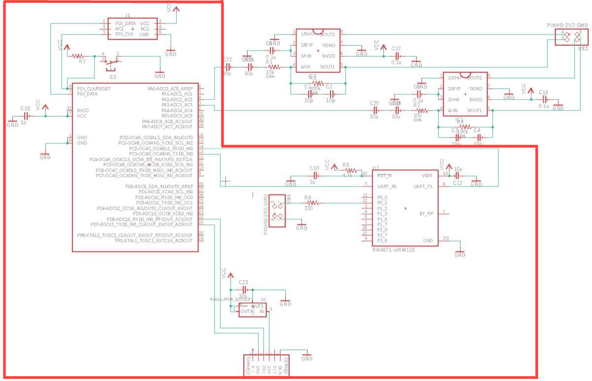
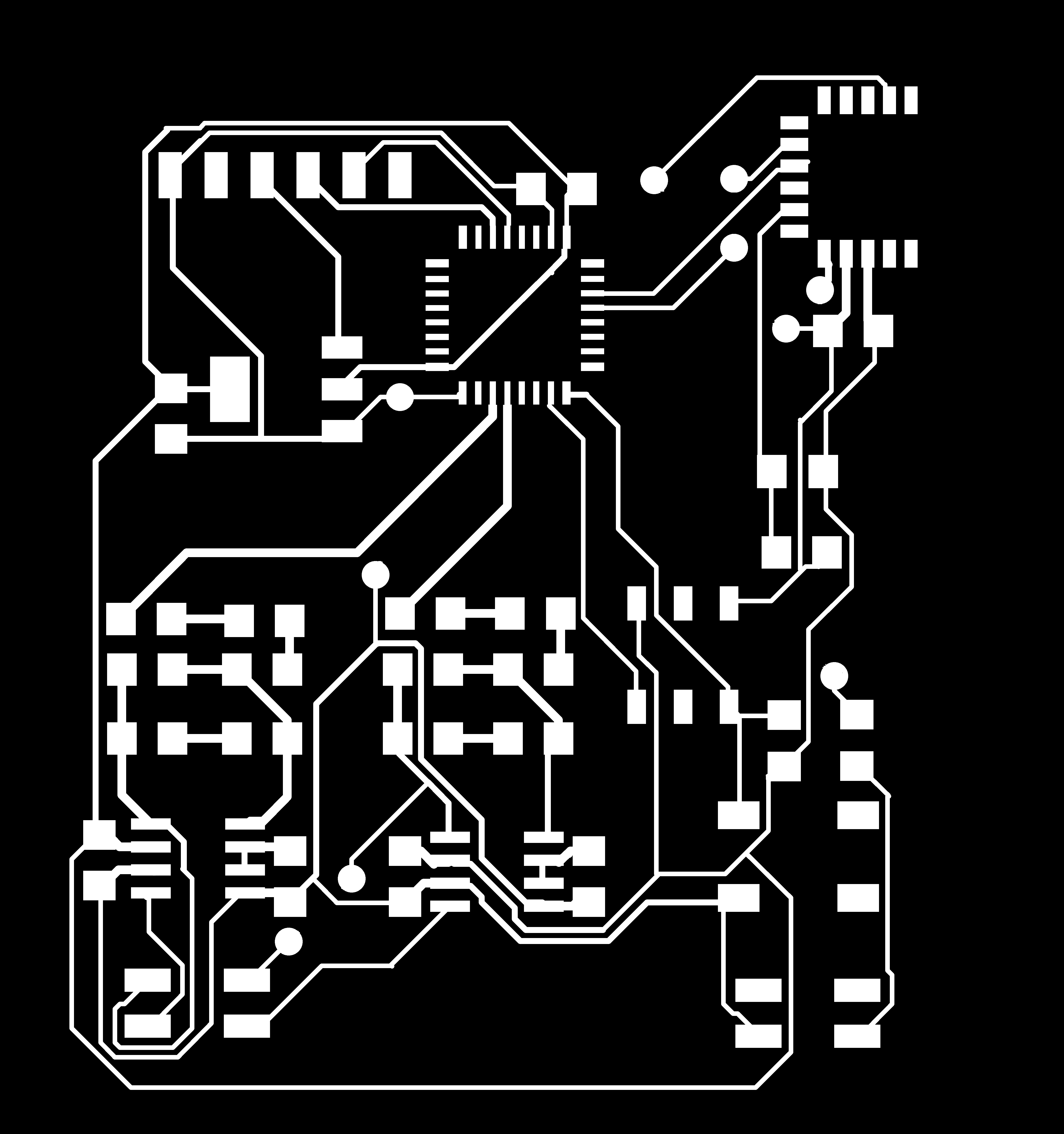
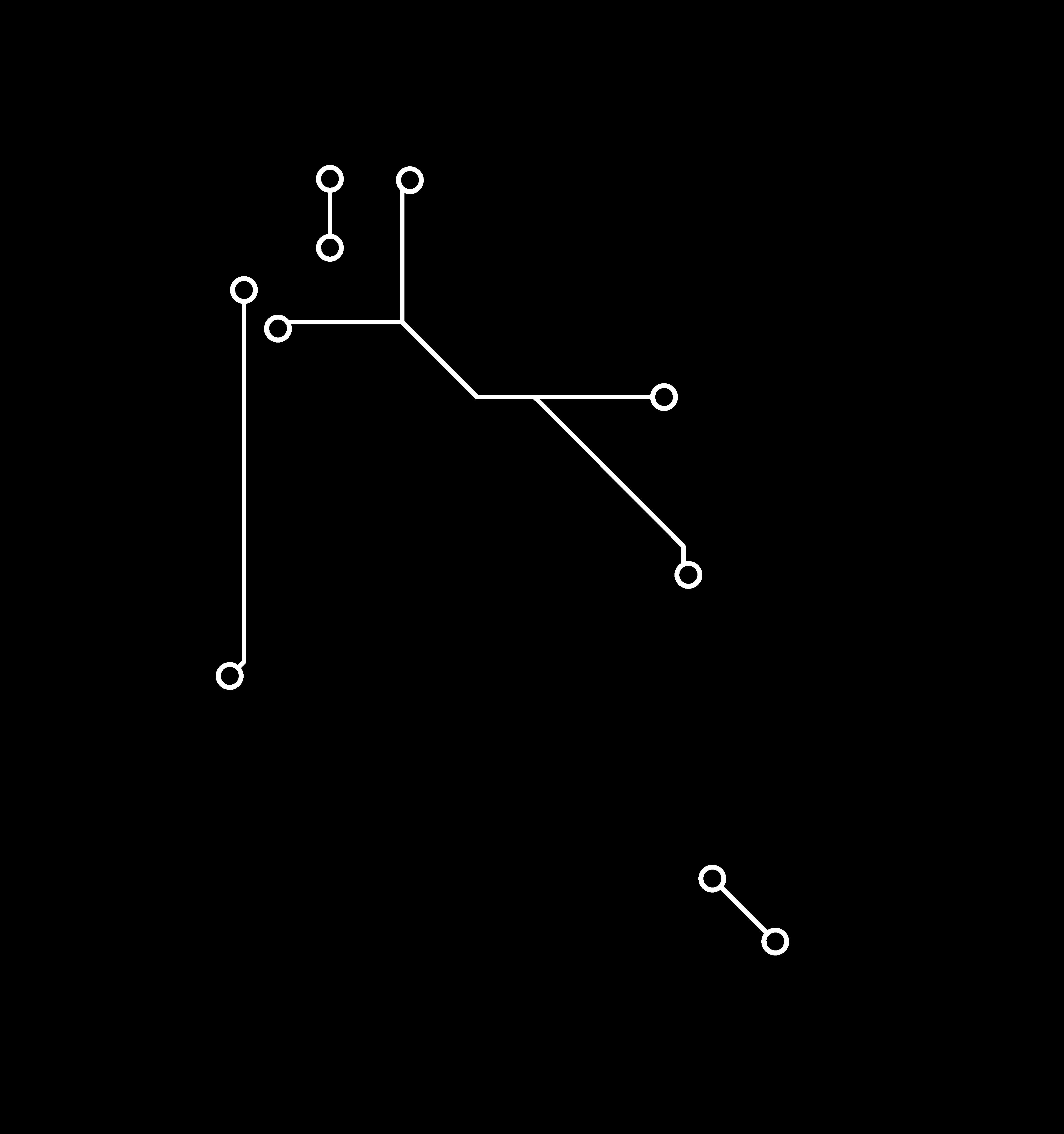
 Final design of the "Bluetooth+ DAC board + preamp" board (this week's focus is in red)
This week, our assignment is to connect at least two processors into a wired or wireless network and communicate between them. I chose to work towards my final project and designed the bluetooth device (based on the RN4871 module) that would communicate between the XMega16e5 and the device connected wirelessly (a mobile phone). Though the final goal for this board is to transmit the audio signal, for this week, I have set an aim to send the message through the serial connection to the XMega, which would then send the message to the phone via the bluetooth. The continuation of this work (in which the audio signal is send from the bluetooth to the microcontroller) can be found in the Final Project page here.
.The bluetooth board, which I planned to use for this week, actually contains more components, as it will eventually be sending the audio profile over bluetooth, and pre-amplifing the audio signal (covered here). This week, however, I have finally triple checked all the connections/components/configurations and layed out the board.
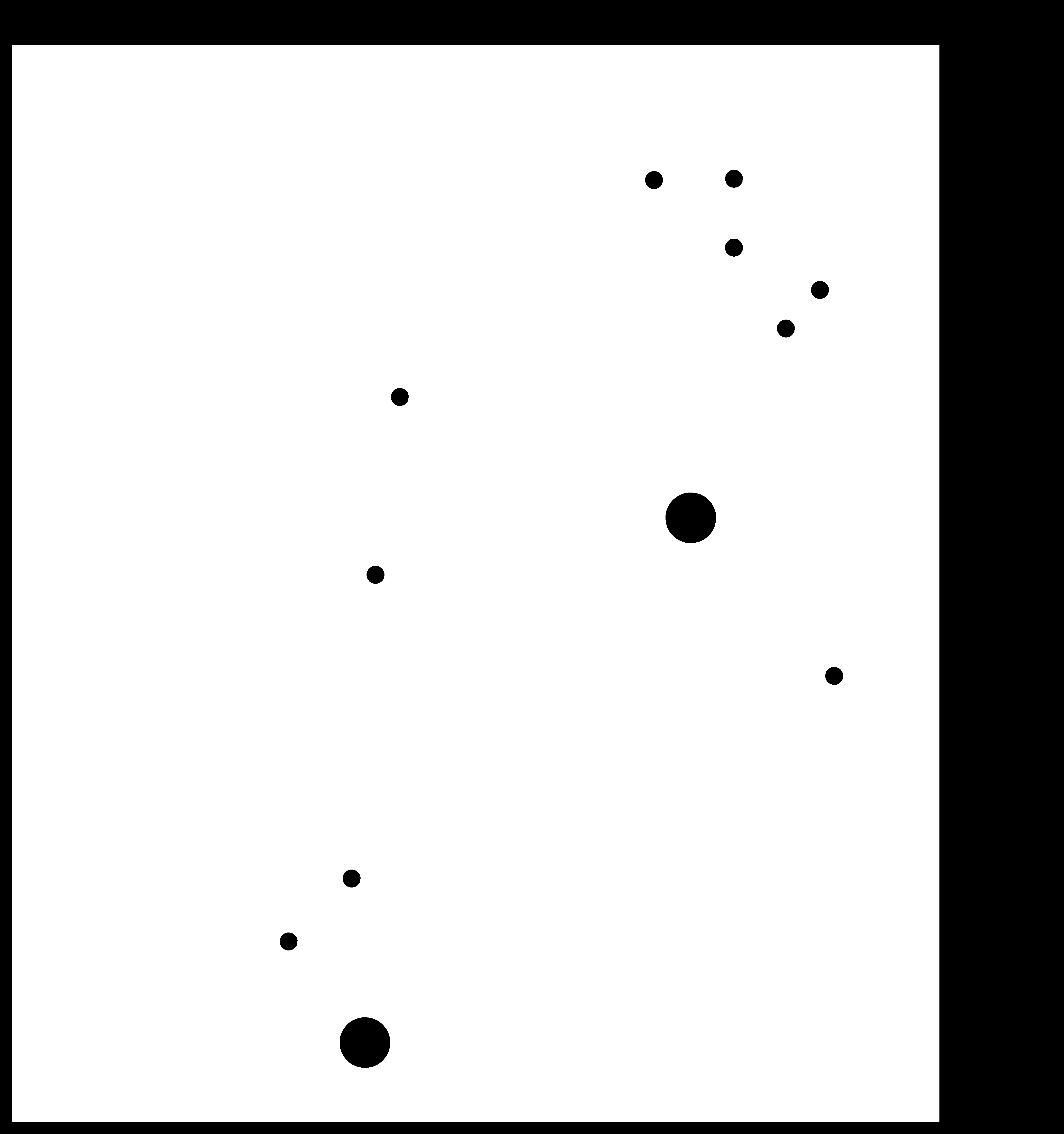
After 2 days of struggle, trying to place all the wirings in one layer, I gave up and just created 10 vias. It means that I finally need to learn how to mill the double-sided PCB. Though this seems to be a rare choice, I decided to do so with the Rolland milling maching.
Final design of the "Bluetooth+ DAC board + preamp" board (this week's focus is in red)
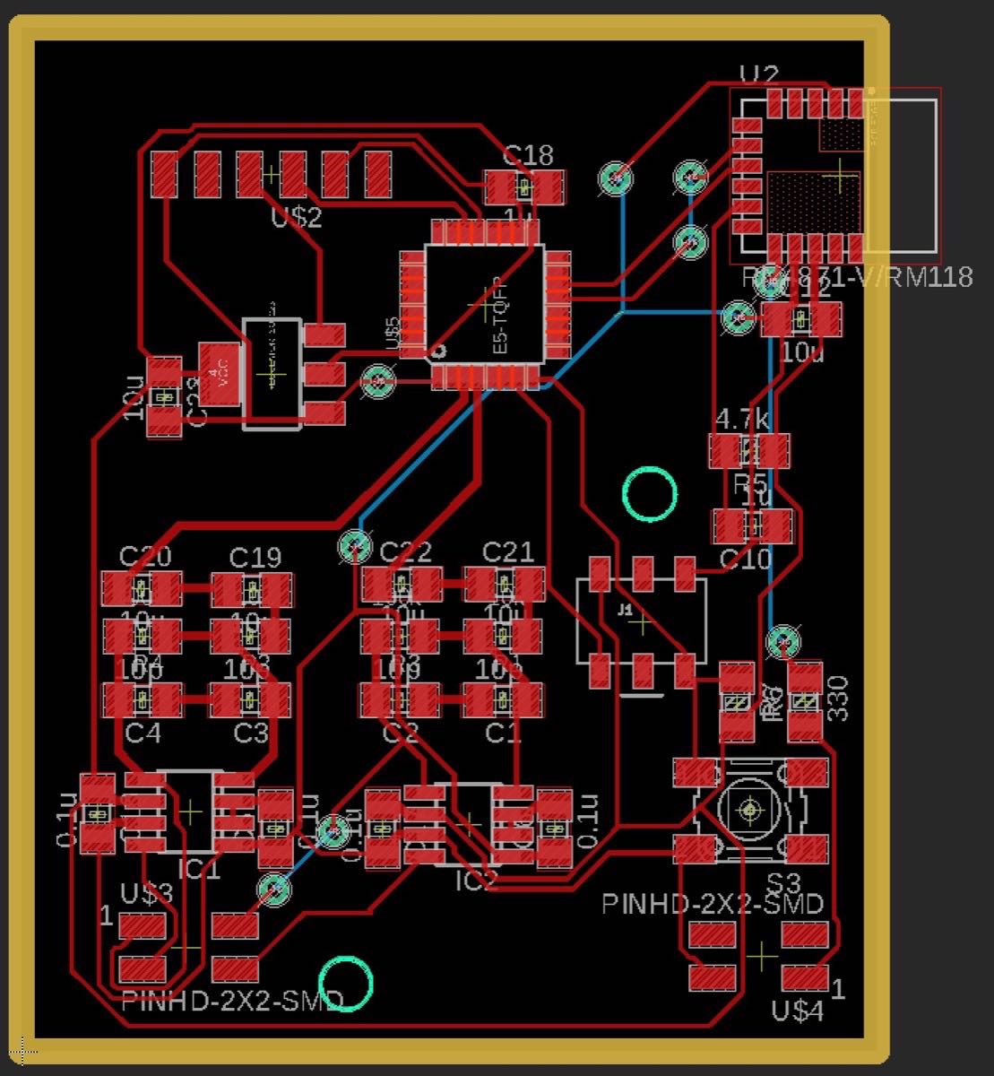 Arranged components
The trick to succesfully mill the second layer (with an insufficiently capable tool like Roland) is to cut a circle at the corner of the cut, such that to tightly align the flipped PCB board along its edges.
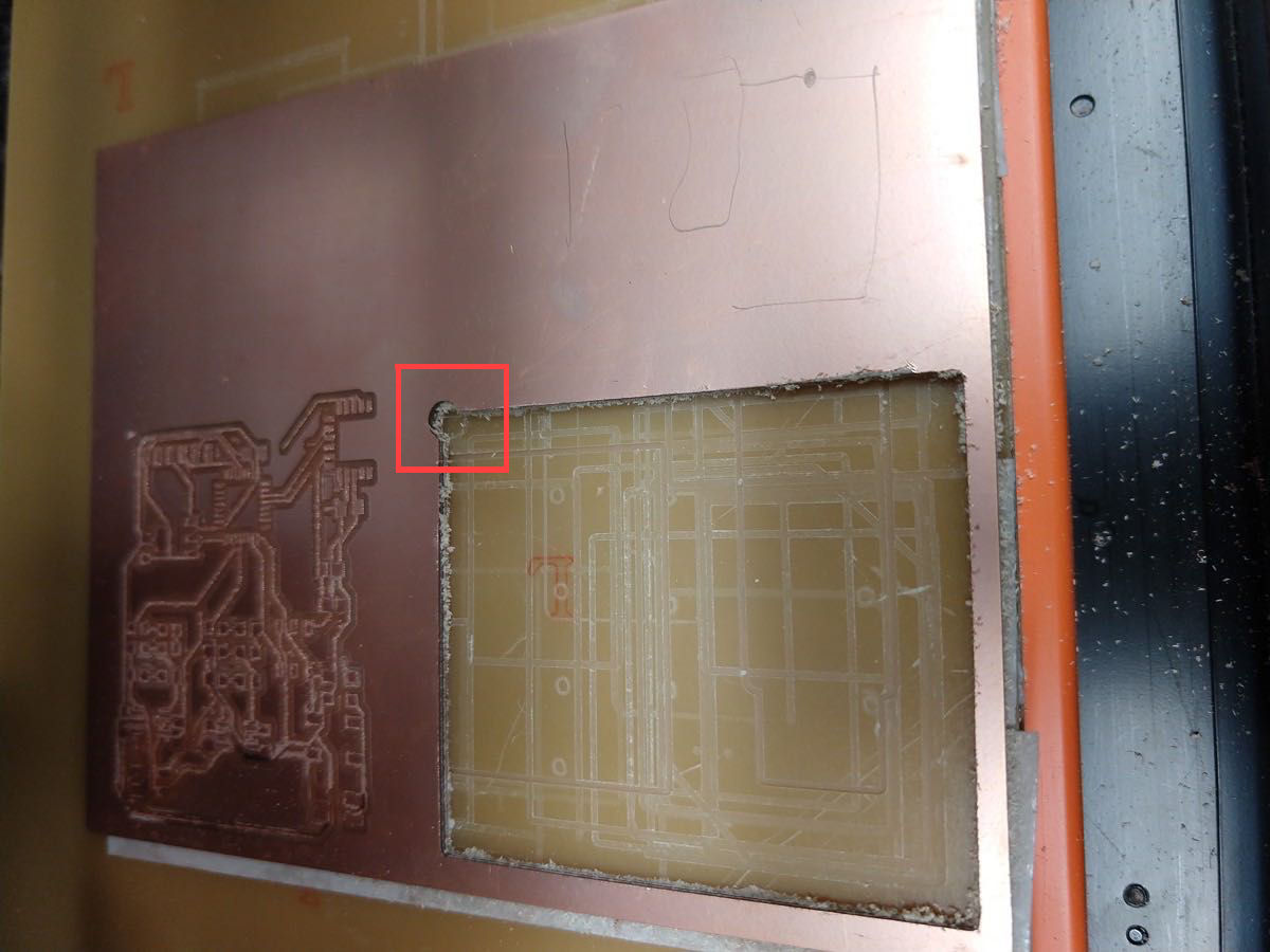 Result of the 2-step outline cut (2nd step is cutting a circle)
 The Neil's trick to align the first layer with the second one
2 steps must follow this procedure in order to get a proper alignment:
After a few failures to follow those two steps, I have eventually milled my first 2-layer board. There is a sligh misalignment of holes and the second layer traces, but that was not critical, since I have filled the vias with the 1 mm wire (rather than with rivets, which unfortunately haven't been delivered on time)
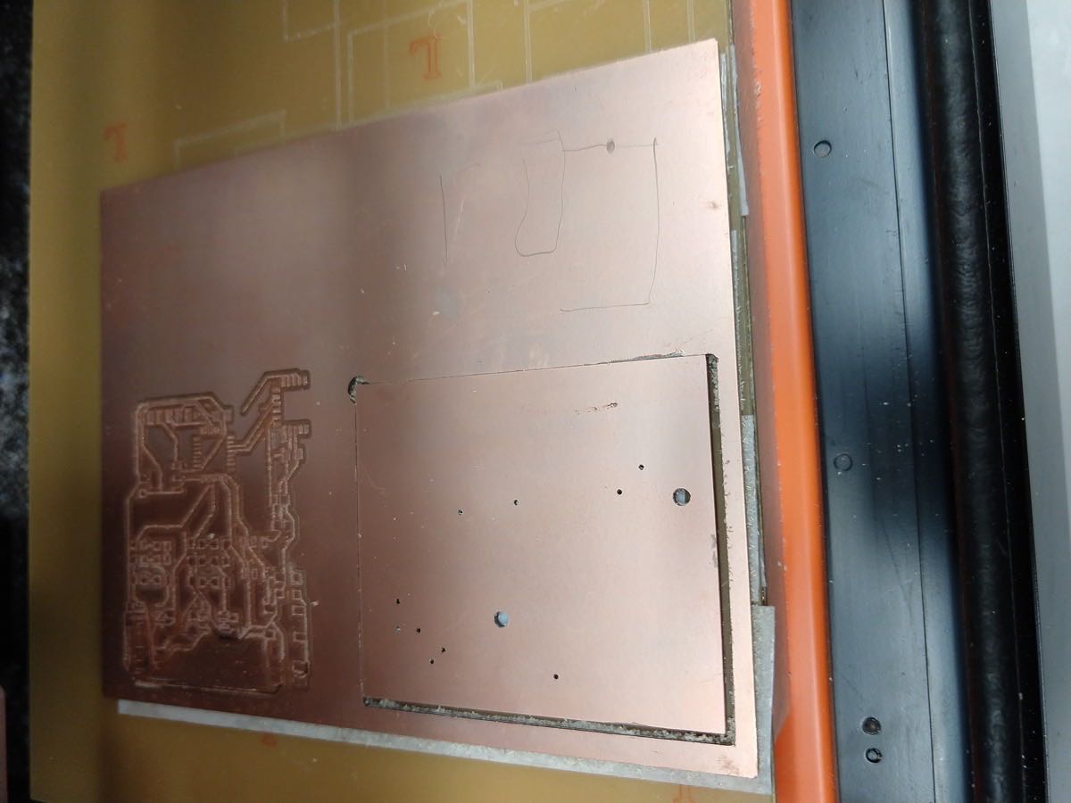
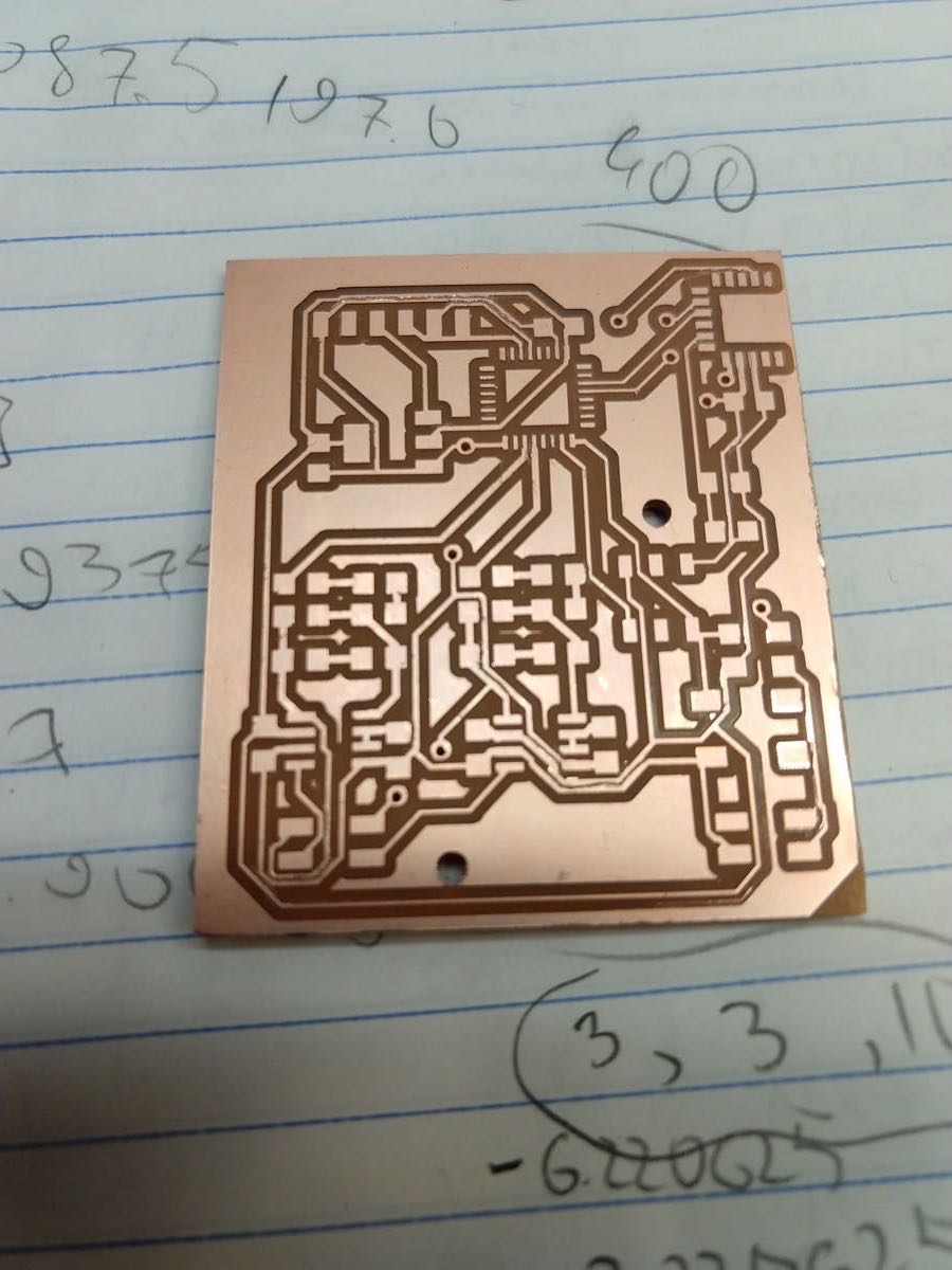 Milled board (1st layer)
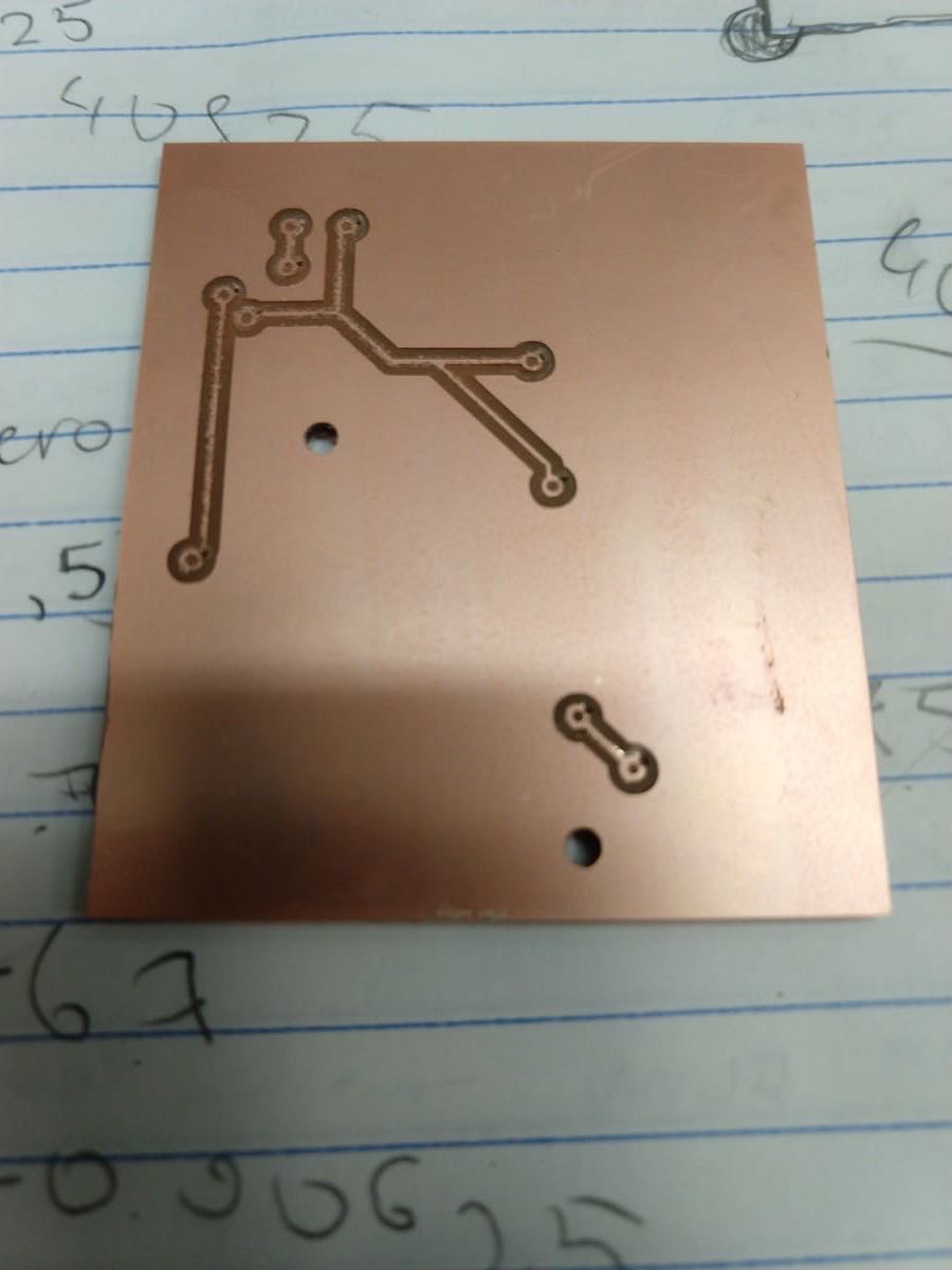 Milled board (2nd layer)
The substitution of rivets with the wire is straightforward: one needs to stick the closely fit wire through the milled hole, bend it on both sides, trim the wire, end solder it on both sides of the board.
After making the vias and stuffing the board, I have connected it to the programmer in order to check if I can talk to it.
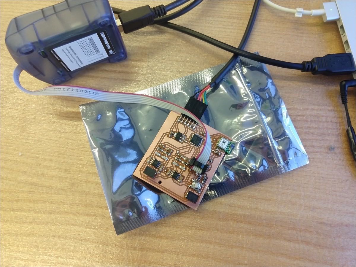 Stuffed board is ready to go
I have realized that connections to the TX and RX on my XMega board are exactly as in the Neil's hello echo board, so this was a great opportunity to check if my board is alive or not.
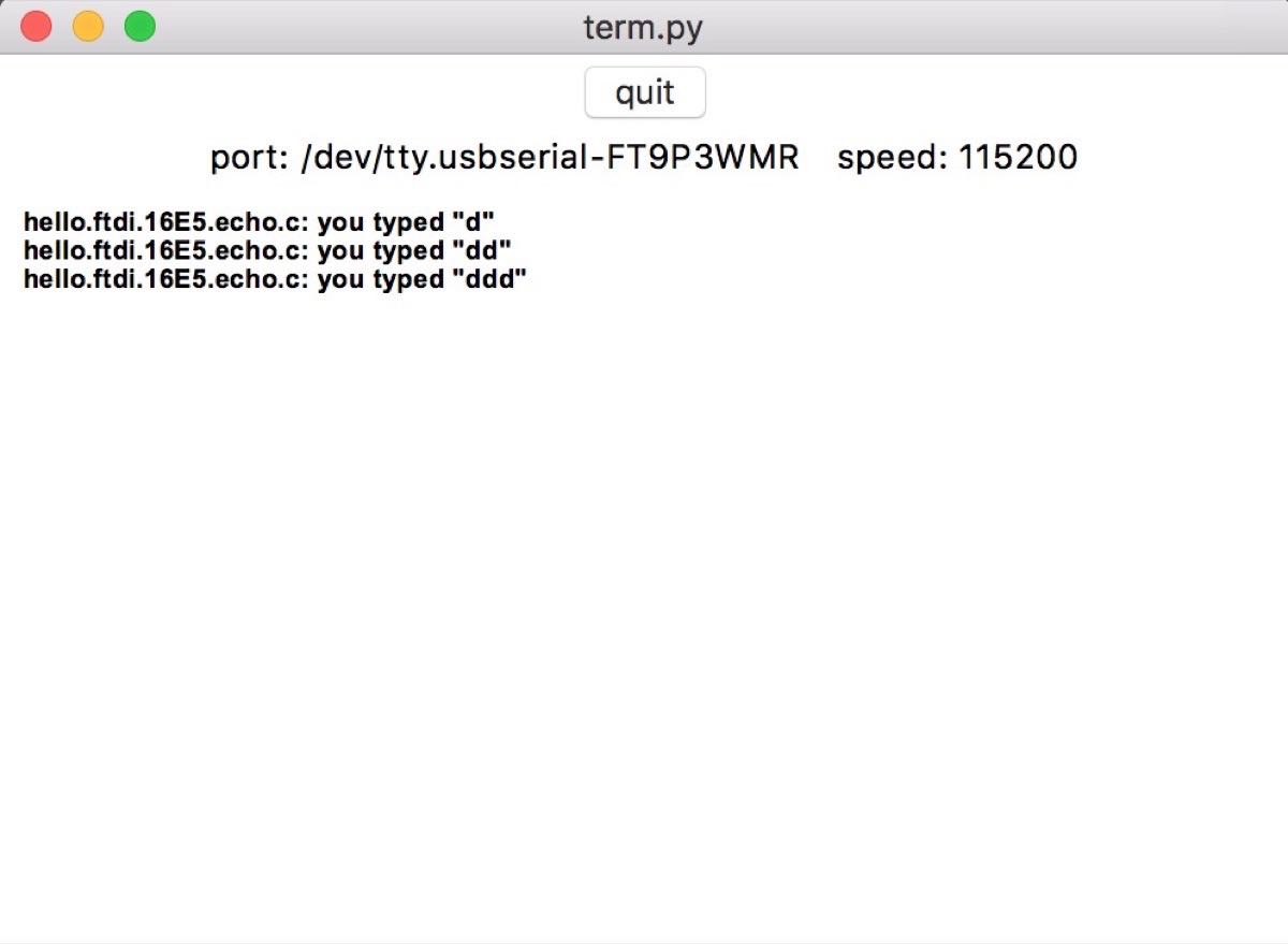 Xmega is passing the "Echo hello world" test (Neil's 1st, 2nd, 3rd code files)
The XMega has succesfully passed the echo communication test and I decided to proceeded with an (unnecessary) detour attempt to load a bootloader on my XMega.
I adored the fact that when working with the Attiny microcontrollers, I could program them with my own programmer (see Week 3). Unfortunately, this programmer is incompatible with XMegas, and since I didn't have time to design my own PDI programmer, I chose to explore the bootloader concept as was suggested by Neil. This can be helpful for time management purposes, as we only have 2 PDI-compatible programmers per section and many people want to use them, which makes it very inconvenient to explore something new. The bootloader option allows for programming the board directly through a serial port (I strongly encourage to buy one for yourself)
For those who want to try this option for XMegas or ATMegas, XBOOT is a great project. Here, one can find all the relevant files, and help. I have compiled this from source, after I have modified the .mk configuration file to fit the XMega16e5 board, and compiled which I took from our stock
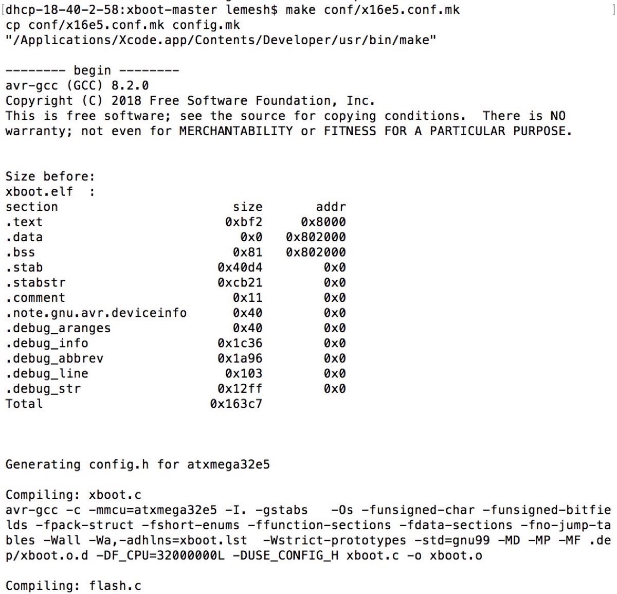 Creating a bootloader hex file
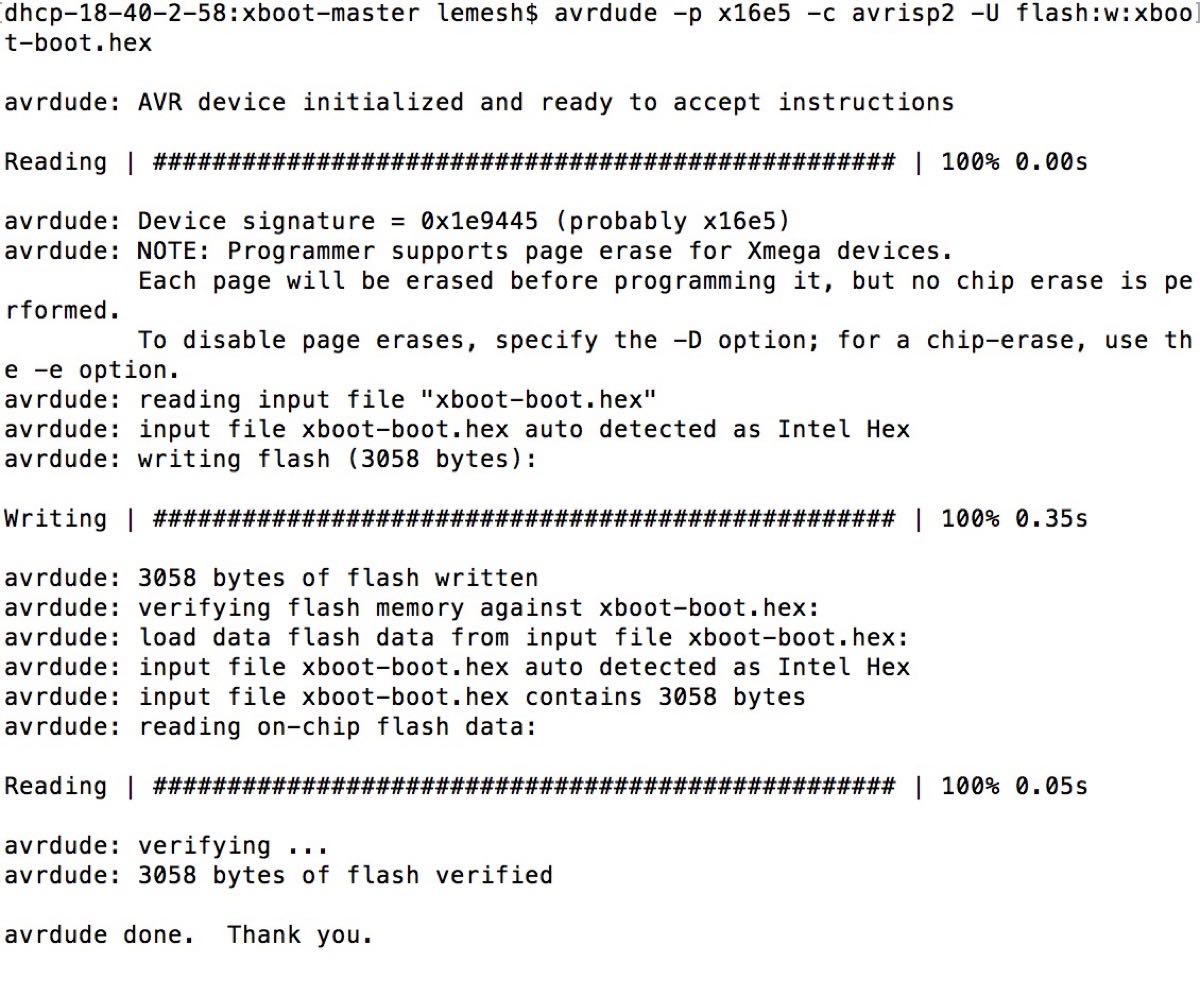 Uploading the bootloader to the XMega
Generating the bootloader .hex file and uploading it to the XMega turned out to be easy. However, when it came to uploading a software (through the serial port) it was unsuccessfull after many attempts to change the configuration files. I even connected the RTS pin to the UART port of the XMega, but it still didn't help.
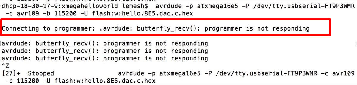 Bootloader does not respond
For the purpose of saving time, I moved on to communicating with the Bluetooth.
Now it is time to learn how to actually have an informative talk with XMega. I stronghly suggest going through the tutorial for the XMega family, or at least folllow this introduction. I decided to start from writing a simple piece of c-code with the only purpose of sending the "$$$" message to the Bluetooth whenever the "a" button is pressed. (download it here and here). Why "$$$"? Well, after a long struggle with trying to hear something from the Bluetooth module, this turned out to be the exact command that I needed to wake it up (always read the datasheet first!).
Before coming across this "$$$" pre-command trick, I have almost gave up on this assignment. But before doing so, I've taken a scope, and checked if the Bluetooth responds to resetting it (I unfortunately did not incorporate the Bluetooth reset button like the one created for XMega, so I had to short the C10 capacitor manually).
To my surprise, the board responded! Thanks to our TA Ben, we have even managed to decode the RS232 signal (with the Baud rate of 115200), which was sent to the Bluetooth as shown below.
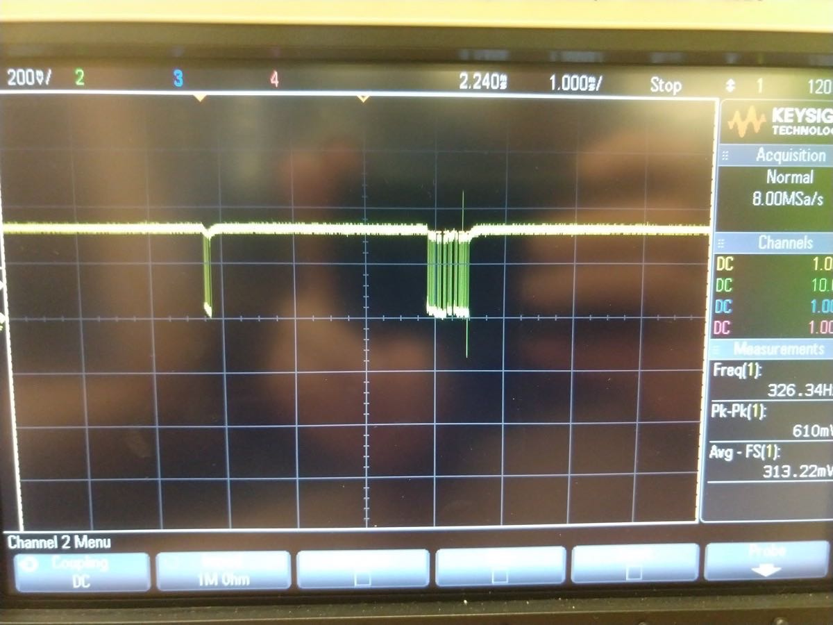 Bluetooth response after the reset (through its TX connection)
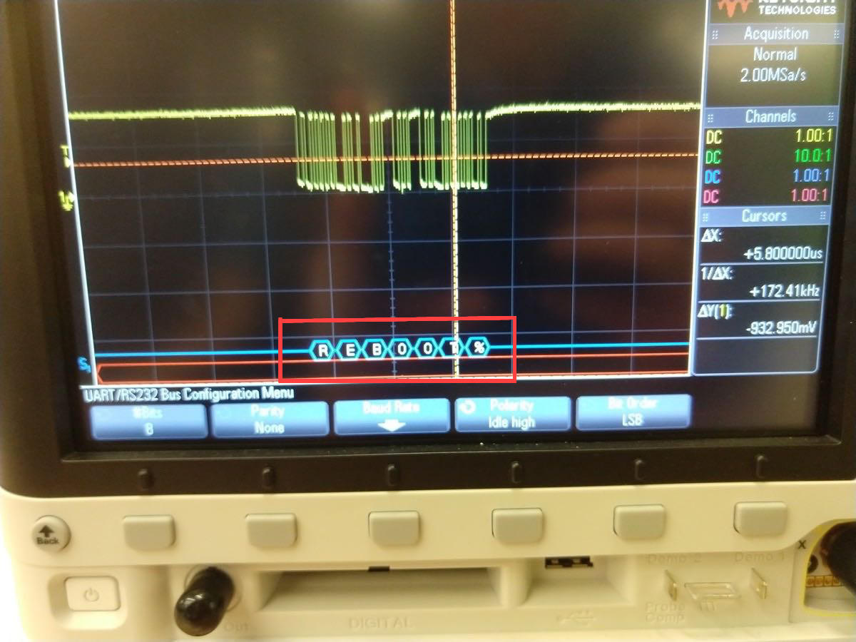 Decoding the Bluetooth reset response. We can read the Matrix!
Now, having become convinced that the module is actually alive, I have started to try to decode what exactly I was sending. It turned out that though I did send the "$$$" command, I didn't give it enough timing afterwards, so that was followed by the Carriage Return sign, which I ignorantly used in the C-code.
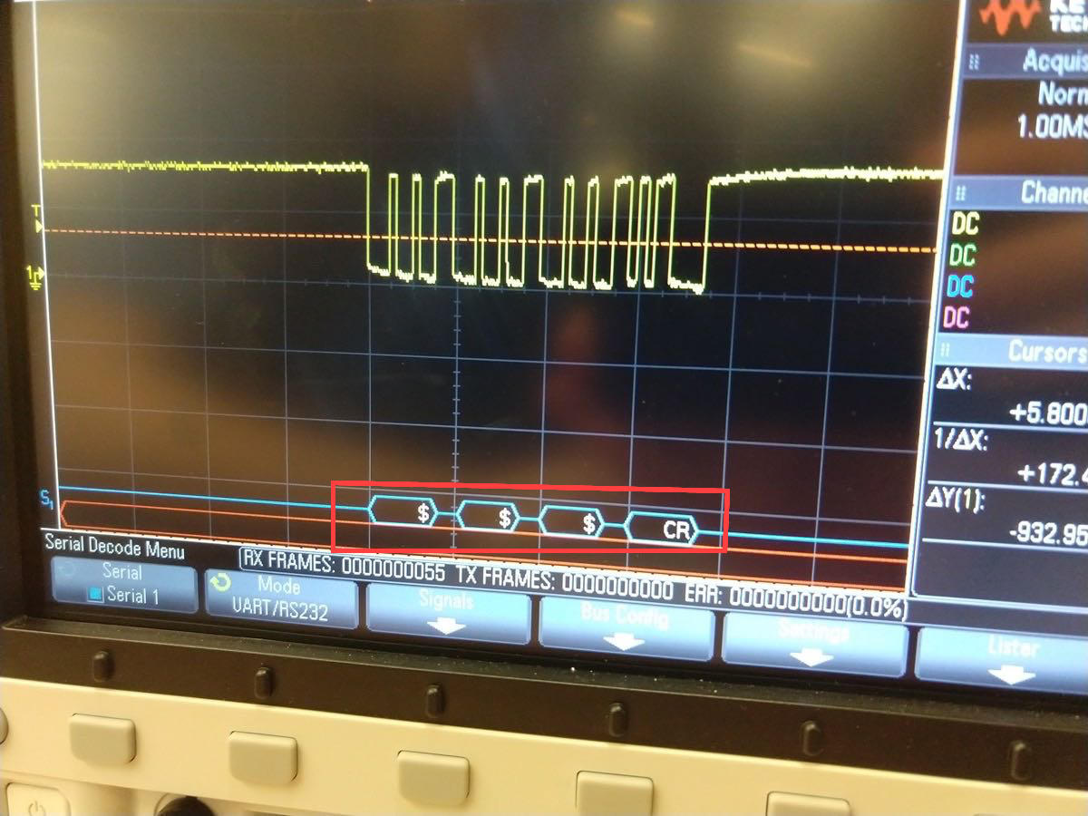 Waking up the Bluetooth with the "$$$" command (through its RX)
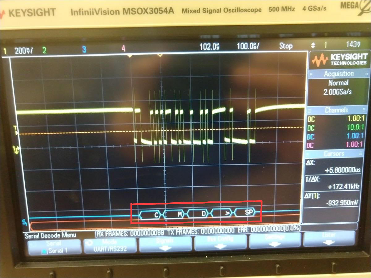 Hearing the response from the Bluetooth to "$$$" (through its TX)
It turns out that even though I can clearly send the '$$$' command (with an exact baud rate of 115200), using Neil's "get_char" program doesn't work well with Xmega. By the time get_char starts reading the data, bluetooth has sent the entire wake up call ("CMD>SP') already, so the get_char program keeps on freezing the execution.
It seems inevitable for me to properly establish the asymmetric UART protocol, in which I assign the alternative RX and TX functions for my pins and establish interrupts instead of a constant check of what is currently stored in the registers. After reading the manual I have figured most of the parameters (for the baud rate of 115200 with 0.001% precision, I need to set '-7' in BSCALE register, '2221' in BSEL register by setting USARTC0_BAUDCTRLB = 0x98; USARTC0_BAUDCTRLA = 0xAD;), and realized that my pins C2 and C3 are luckily set by default to the UART alternative function. (however, in XMEGA microcontrollers unlike in Attinys or AtMegas, one can easily remap UART to other pins as well!)
However, I was still not able to print out the bluetooth messages, and this part will be covered in the final project tracking page, where my main task is to use this asynchronous communication for sending the digital audio signal. Please, proceed here.