 Components of the tube amplifier
We have finally approached the wildcard week - the week in which we choose a topic/technique of interest (in the world of a digital fabrication), formulate our own weekly "assignment" and document the progress.
For the Wildcard week, I have chosen the topic of Sheet metal fabrication, for which I have come up with the following task: "Use CAD tools to design the sheet metal enclosure for your chosen 3D design, cut it, fold it, and describe the major design considerations."
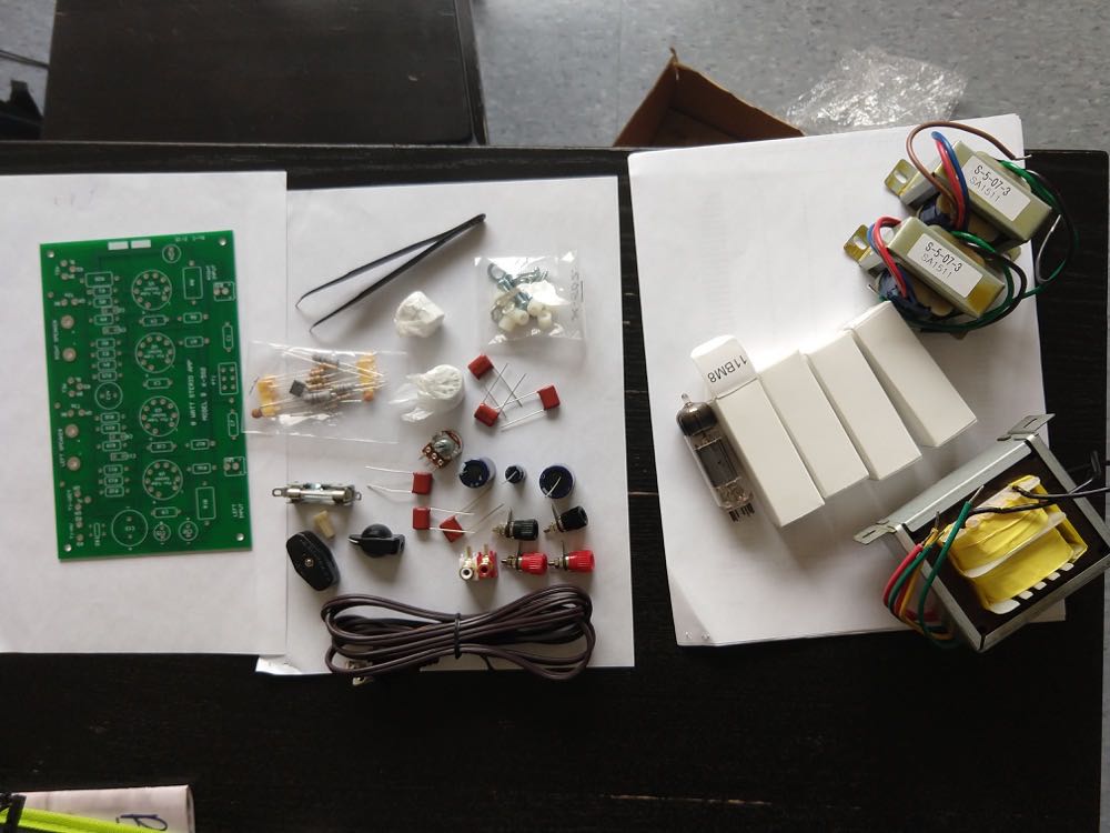
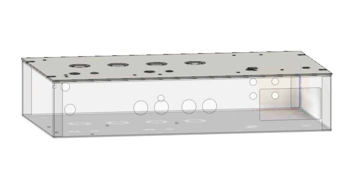
I chose to explore the topic of sheet metal fabrication, as I was in dire need to have proper chassis enclosure for my tube amplifier (Final project). In short, I needed to assemble all my components and place them inside of a steel 10''x6''x2'' box as shown below.
Components of the tube amplifier
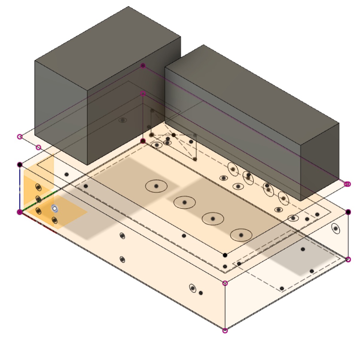 Initial sketches for the amplifier and transformers enclosure
I also decided to put an enclsure around the transformers, since this will definitely make the amp much more more aesthetic and safe.
In this design, the PCB will be attached to the bottom of the top lid (which will ensure that an intricate wiring is not an issue)
Now, before starting to design a 2D metal sheet layout, one needs to decide what material/thickness to use. In my case, I will be working with the 16 and 24 gauge steel. The 16 gauge steel is for the box lid (to make it stronger) and the 24 gauge steel is for everything else (smaller thickness allows to bend it easily and have it with a relatively light final weight). Steel is also easy and safe to weld (unlike in the case of aluminium)
Fusion 360 has a great "Sheet Metal" tool, which enables extruding the sheets of metal. To extrude the new flange, simply choose the edge of interest and press "Create" -> "Flange".
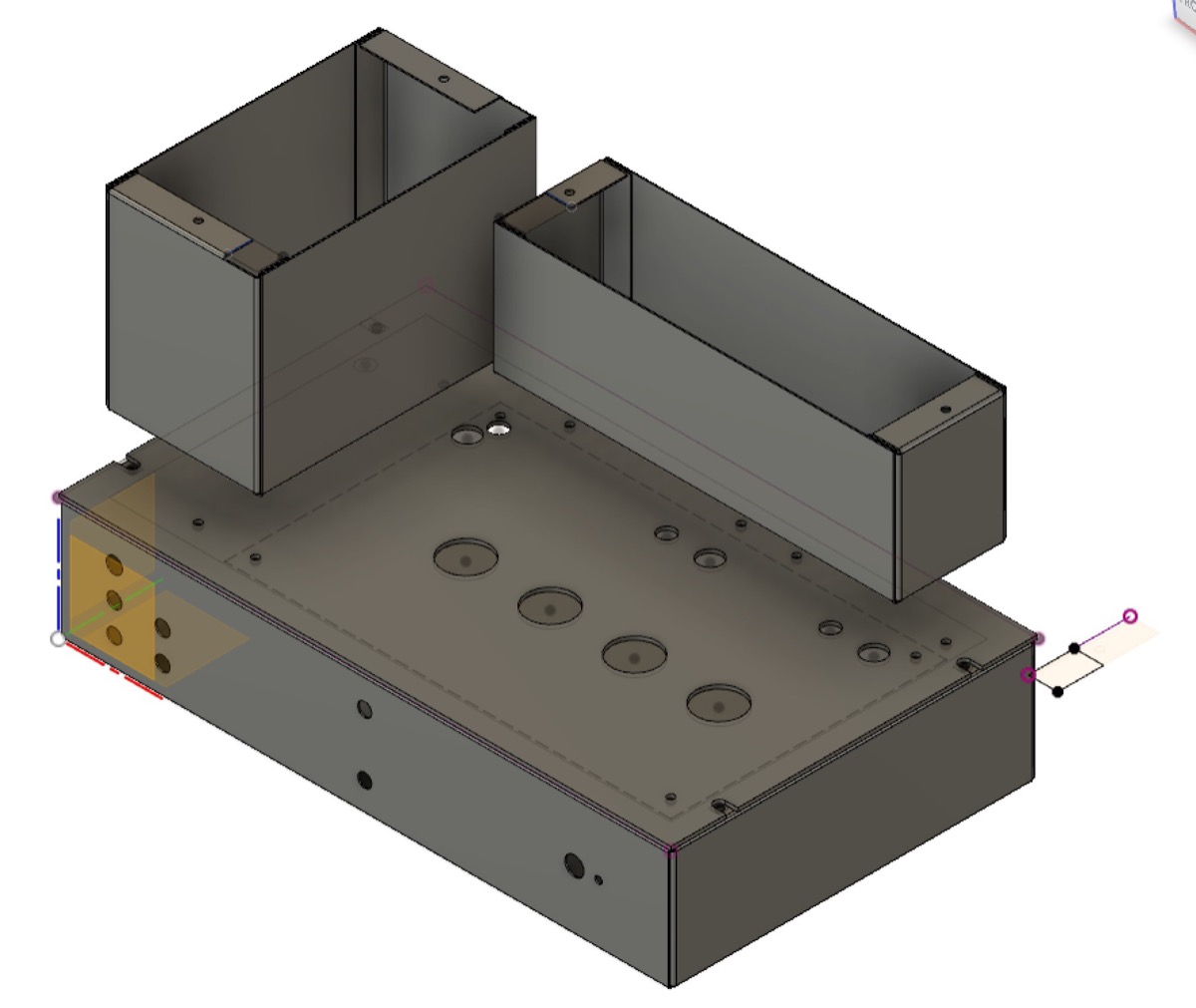
Using the bottom planes of my 3D box designs, I have subsequently performed this operation, leading to the following appearance for the transformer enclosure and its flattened 2D pattern:
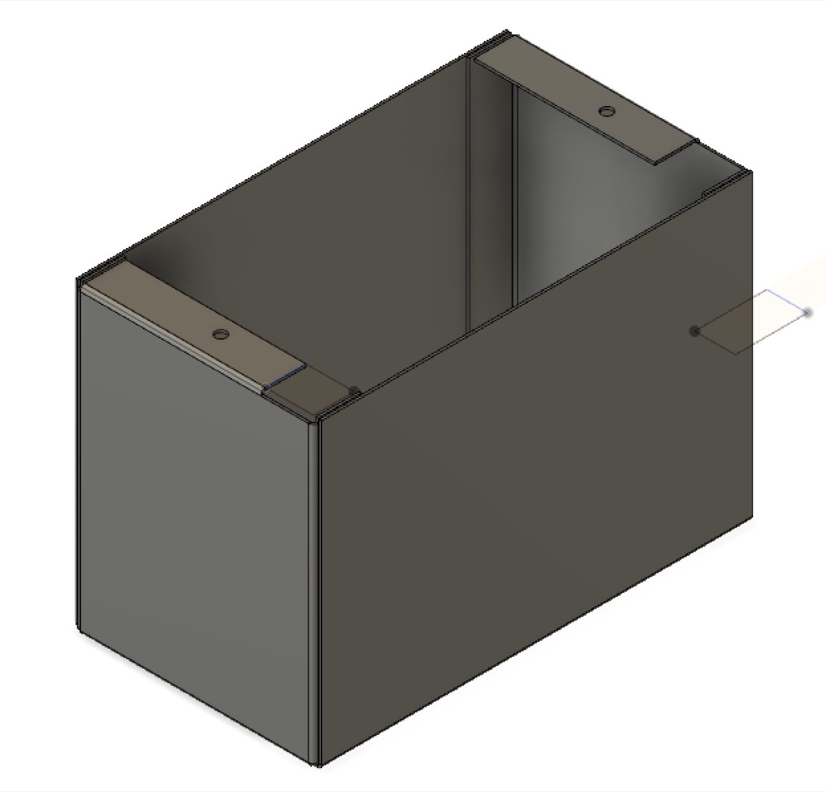 Transformer box enclosure
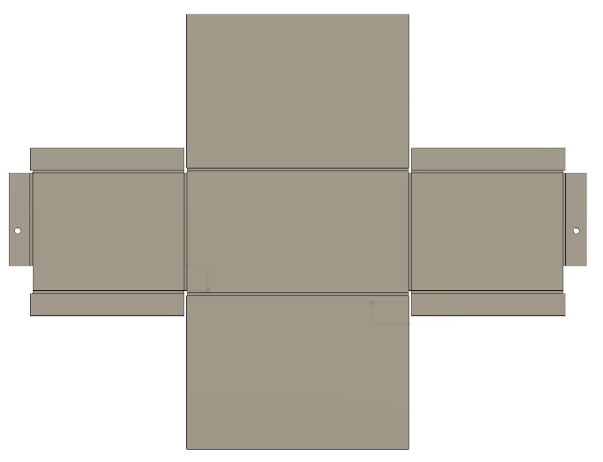 Transformer box enclosure unfolded
I then repeated the same operation for the amplifier enclosure. Additionally, I substracted the cylinders (which were extruded from the designed holes) from the resulting enclosure, leading to the following appearance:
 Amplifier enclosure
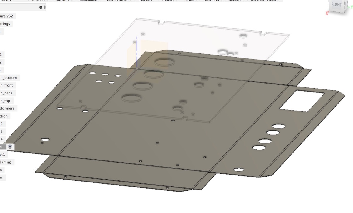 Amplifier enclosure unfolded
Finally, all the design was completed, and I proceeded with generating the dxf files from the flattened patterns (which can be accomplished with the projection operator)
 Complete set of enclosures (transofmer boxes are flipped)
My former plan was to fabricate such structures using the waterjet cutter. Luckily, the wildcard week also featured the lasercutter (Fablight) suitable for working with steel. Fablight turned out to be relatively easy and quick to work with:
Laser-cutting the sheet of stainless steel with the FabLight
Once the cut was ready, I proceeded with extruding the pieces followed by bending the angles.
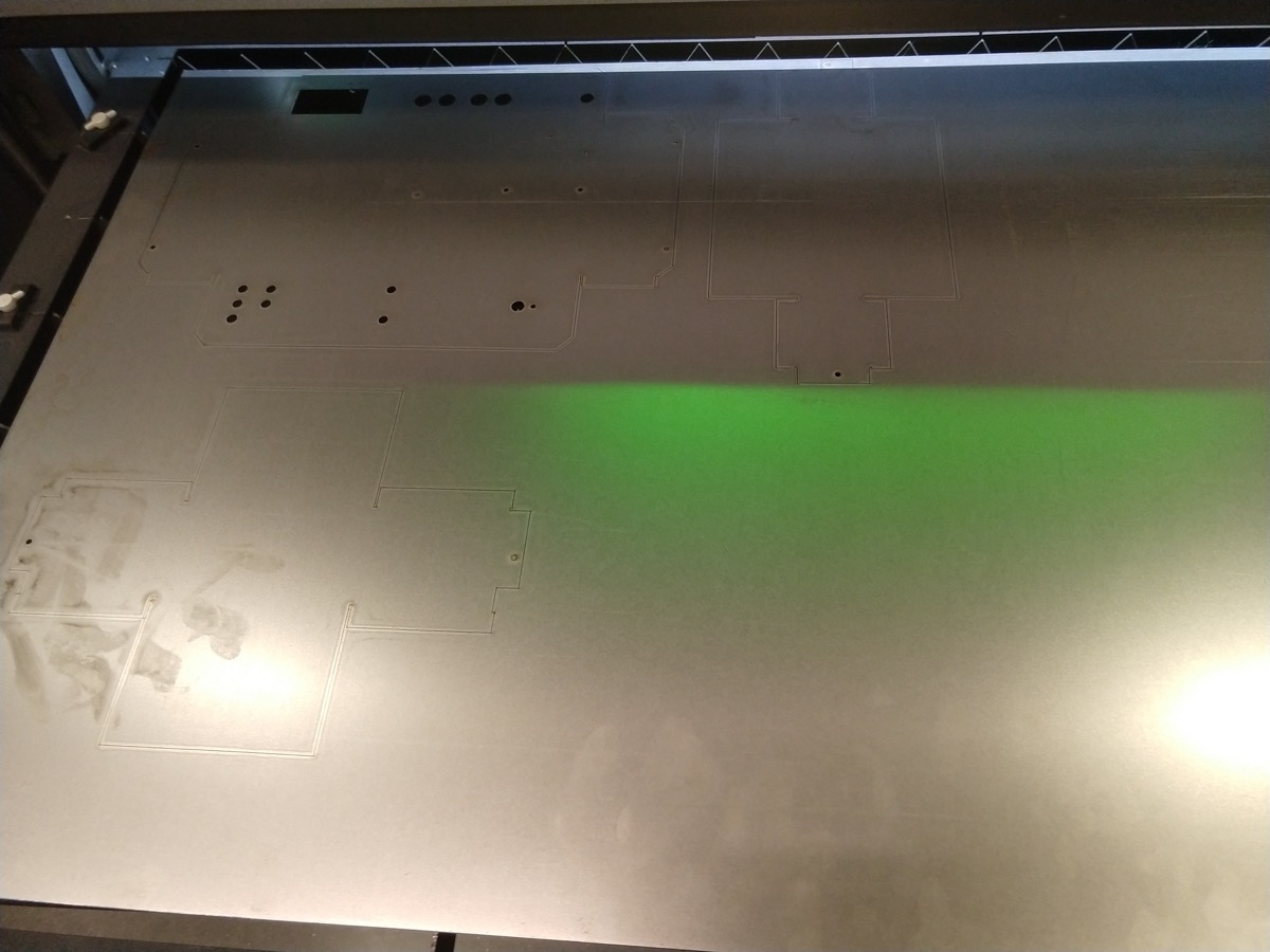 The sheet of steel after the laser-cutting
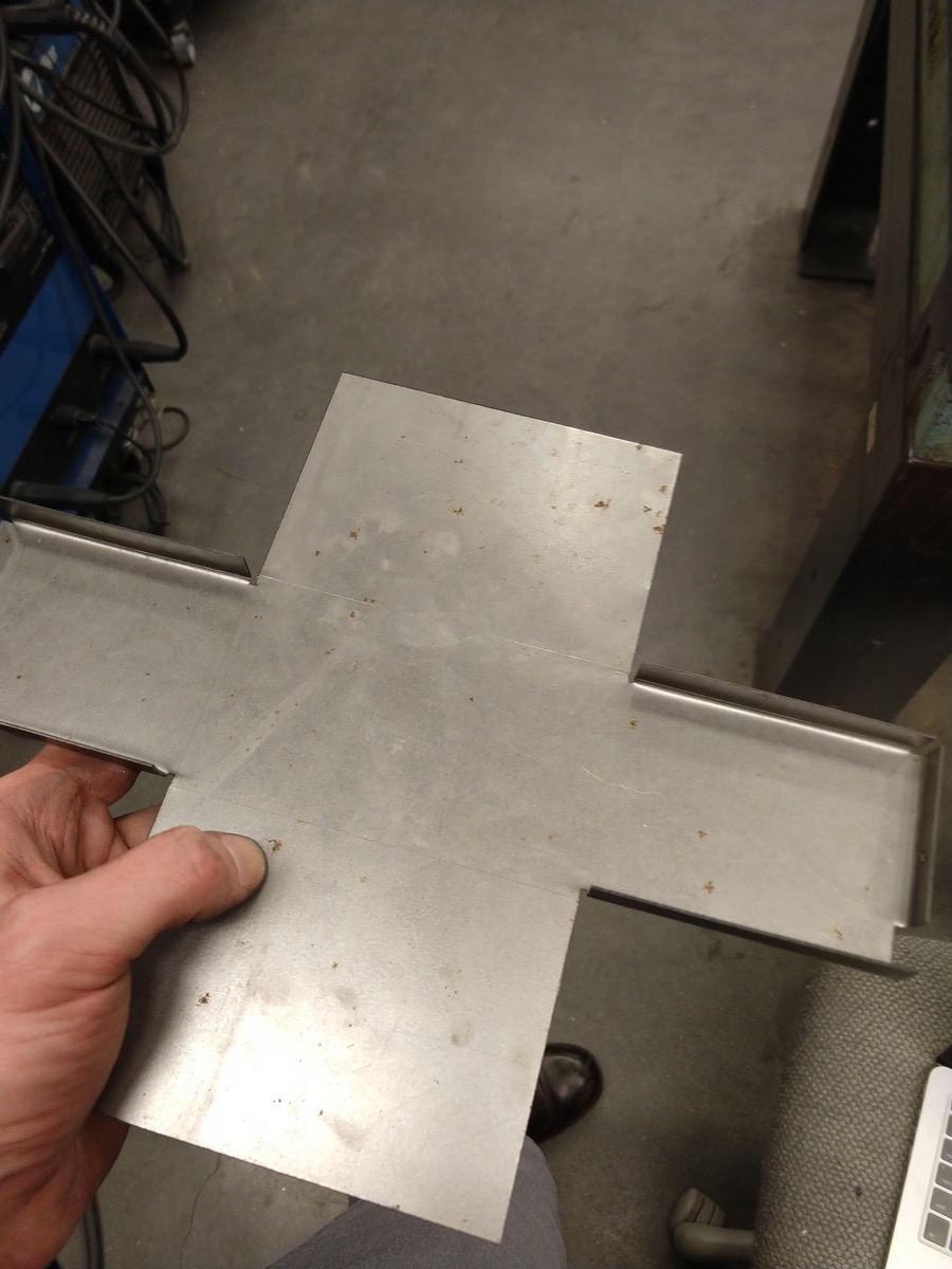 The start of the journey of manual bending
The bending turned out to be the most difficult part of the process. One needs to think really carefully about the ordering of bends, since an incorrect order can result in bends that are virtually impossible to reach with any available tool. In my case, around a half of the bends was performed manually (the bends in the photo above were accomplished with a careful hammering) and for half of them I was able to use this massive bender tool, which makes the process very fun and relatively easy:
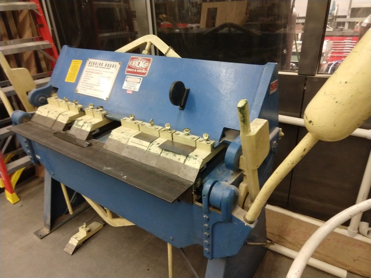 The tool for bending sheets of metal
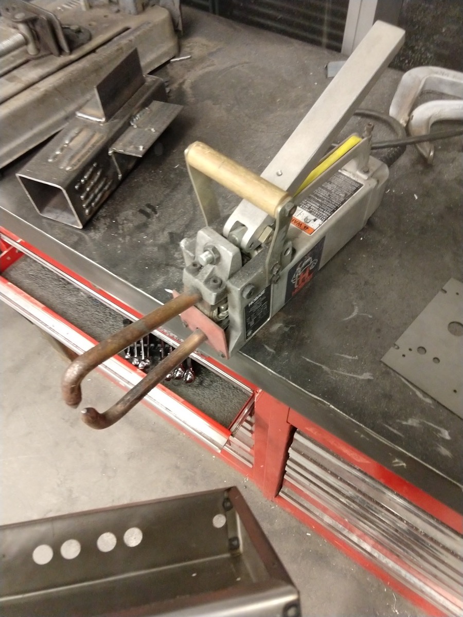 Spot welding tool
The tool is nice, but due to a significant leverage, one can easily smash an incorrectly placed component. Also, reaching the 90 deg. bend angles require a sligh overbending, since steel slightly springs back (the thicker the steel piece, the more it wants to spring back.)
After folding all the sides, I have realized that my final piece was slightly misfit due to the angles being offset from the 90 deg value. However the spot welding tool (shown in the photo above) easily solved this problem, since prior to welding, it applies a significant pressure on the steel pieces that are in contact. To make my enclosures stronger, I have welded them in two spots per every edge.
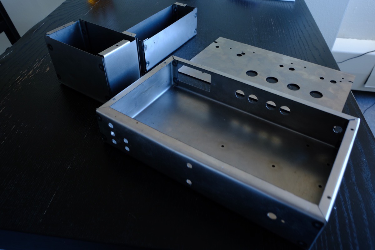 The milling, bending and welding are finished
I was very happy with the resulting work as it had a very high quality appearance.
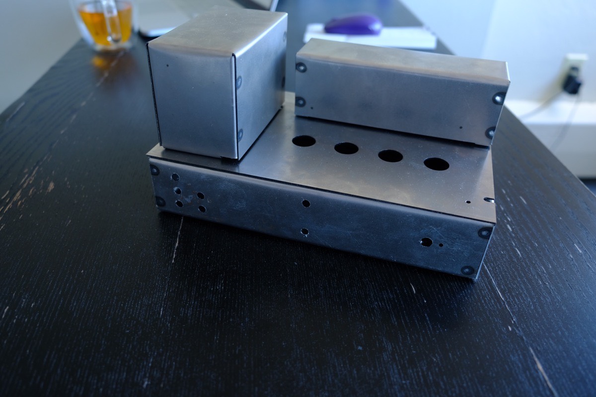 Final enclosure outcome (front view)
 Final enclosure outcome (rear view)