output devices
Output devices.
I tried to make a board that would drive a servo motor. And also one for just an LED.
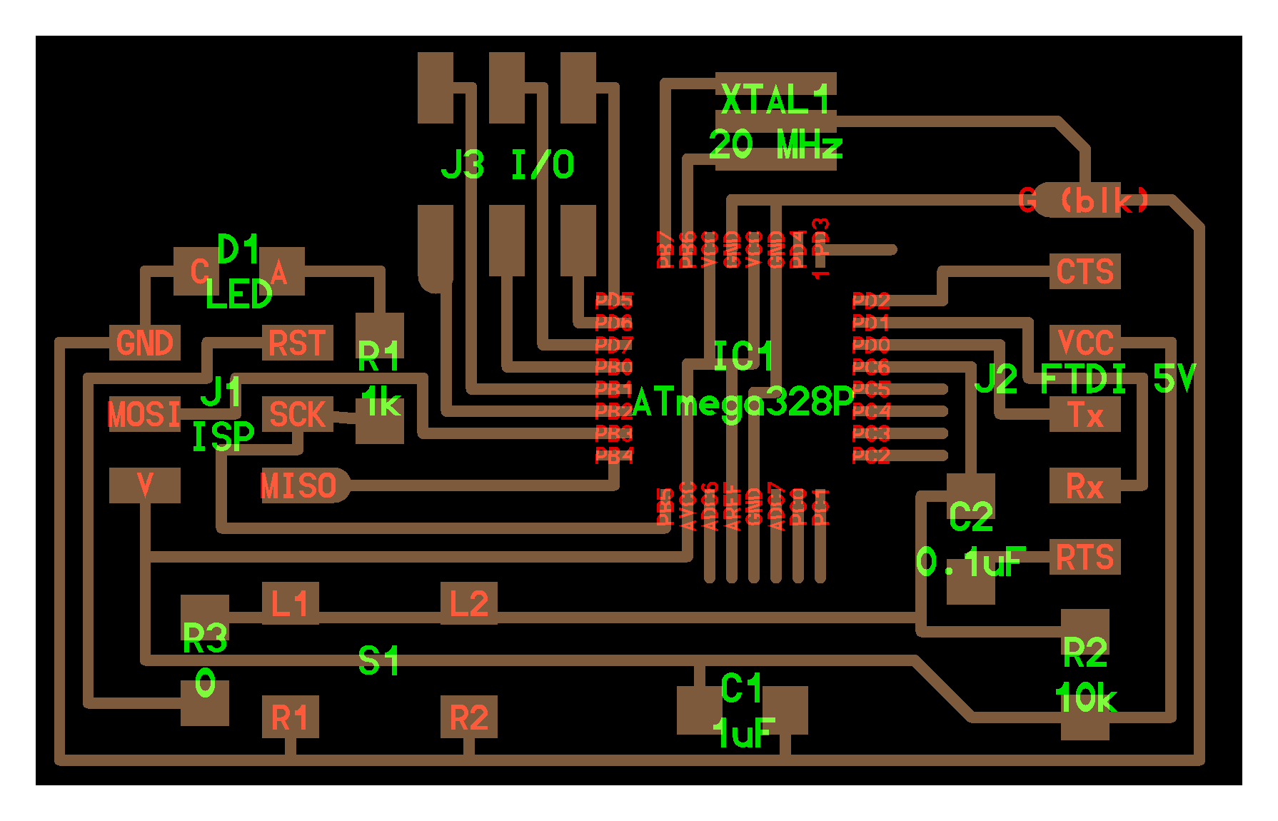
I made a new board based on an ATmega328P (which is what the arduino uno is built up from) for the purposes of making an arduino type board. There have been multiple of these types of board made before, such as the Satshakit, the Fabkit, and Neil's board here. I based my board off of these and off of just reading the datasheet, so I wasn't super confident in it working (so I also made a break-out board for the attiny44, which I was confident would work). The main differences between this and Neil's is that I ditched the ISP header, and I have output traces for all the unused pins. The main difference between this one and the Satshakit is that I don't use a bunch of capacitors in parallel and just go with the recommended capacitance from the datasheet. So hopefully that works fine? I dunno. I had a lot of trouble routing this board, so it could be horrible to solder, too.

So this is the board I made, with the wires connected to where the ISP header would be. And, as it turns out, I regret not just leaving the header in there, because thus far it's been basically impossible to solder the wires onto the board, and to that end actually program it to do anything. In the picture, I've got an LED plugged into the board, because I was trying to turn that on as a way of testing the board, but, again, I haven't been able to get a real connection between my ISP header and the soldered on wires. So this may get abandoned at some point.

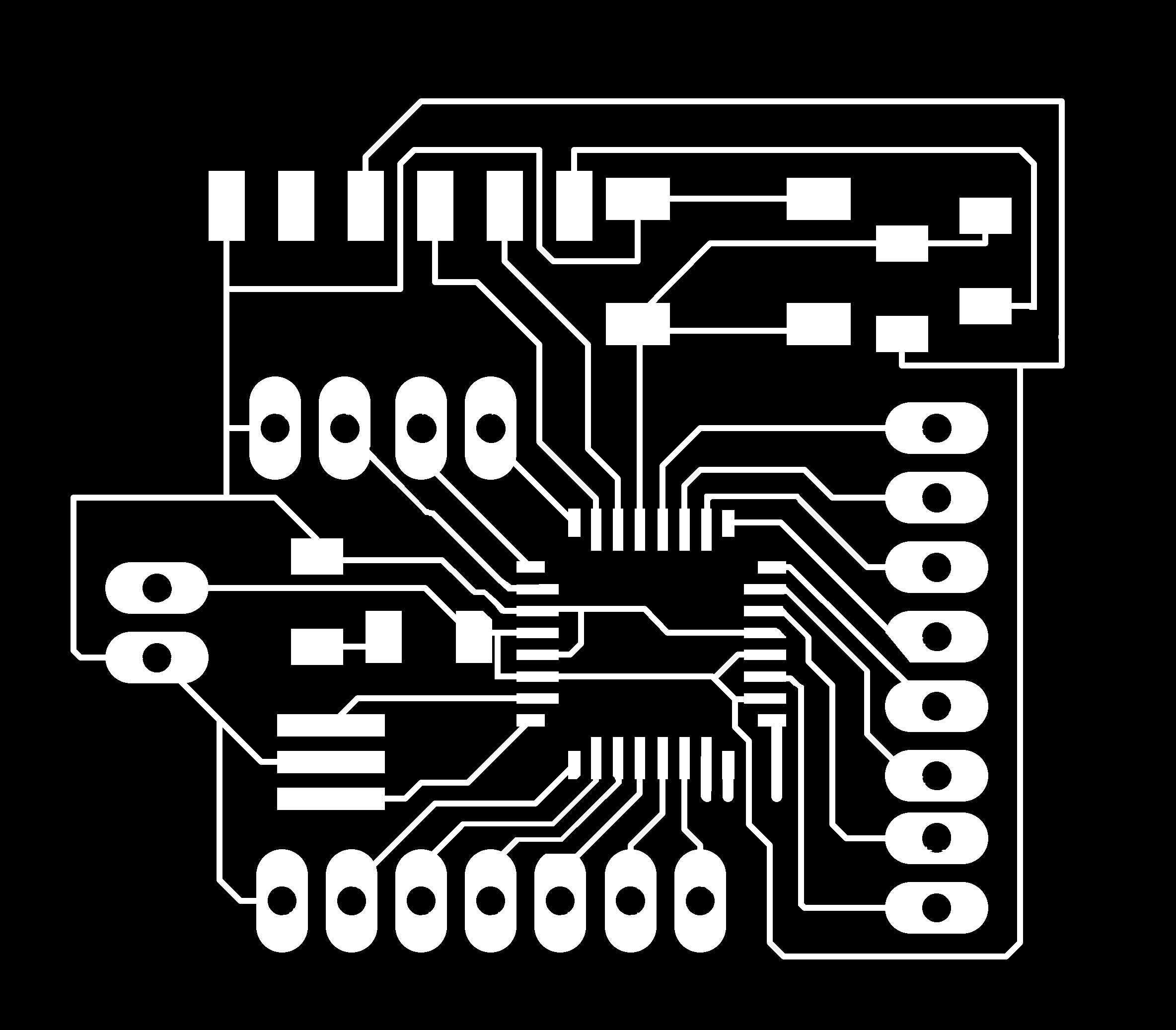
This is the attiny44 breakout board. I wish that I'd added more headers for ground.
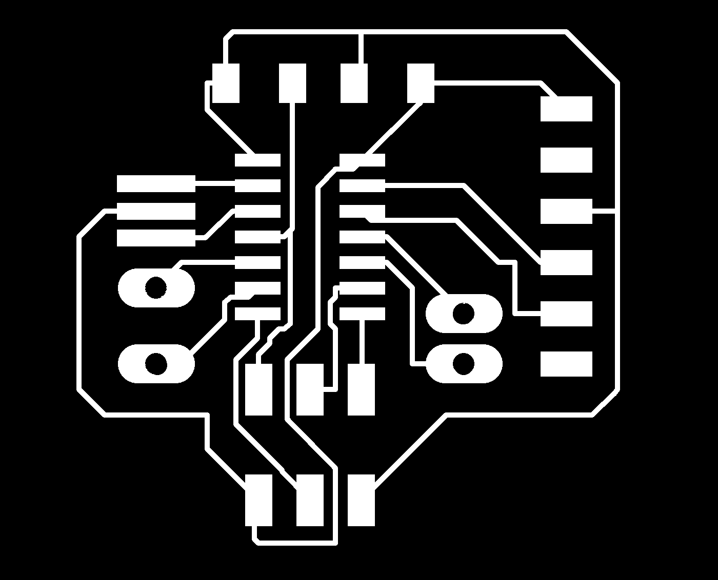
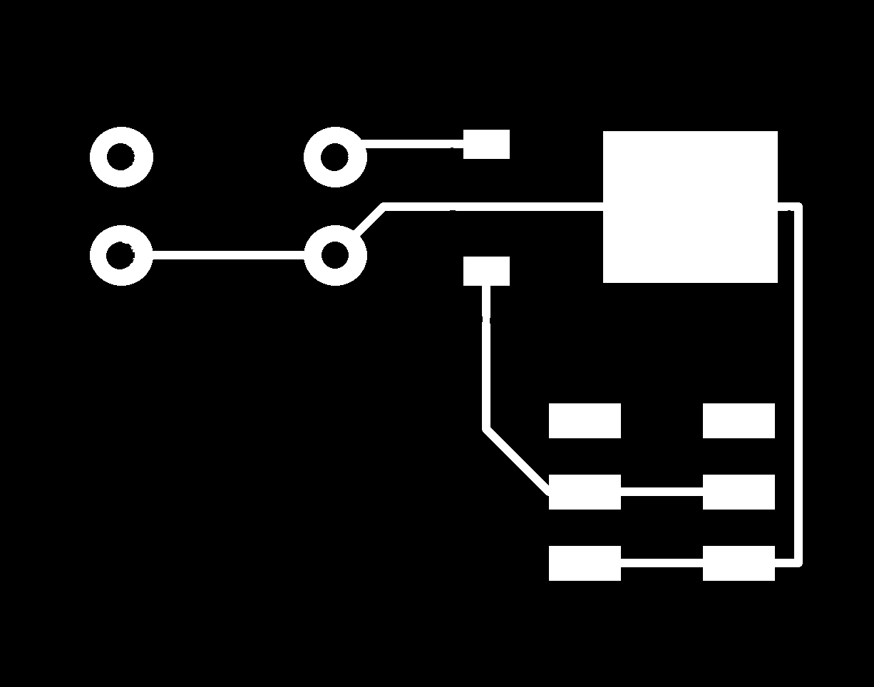
I then made two small boards (one with an LED+resistor) and one to drive the servo. (so you'd run wires from the breakout pins of either the above two boards and to these)

The above board is the same set up as Neil's servo example. It's basically just an ISP header, a power line, and a 5V regulator.
As I was milling the LED break out board (a set of headers for vcc and ground, an LED, and a 499ohm resistor), I encountered a weird error with mods, where it only extracted one edge from my cut file, and then when milling, decided to seemingly center that line? I'm not totally sure what happened. I spent a bit of time trying to change threshold values and such on mods, but whatever I changed would just revert to the original settings when I tried to recalculate the toolpath, so I gave up on that. I have a good amount of normal LEDs from various other projects, so I tested the attiny44 board with one of those, because when free floating, surface mount components are very difficult to deal with.