

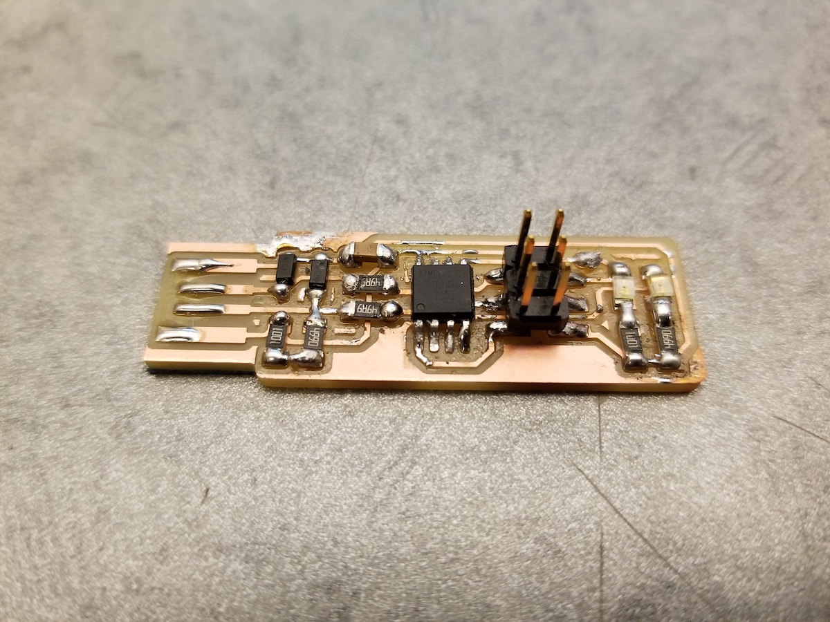
The final product
Here is the finished board. I never realised soldering tiny components is such a tricky task. I have soldered wires and some components with long leads onto PCB's with drilled holes in them, but this was far more challenging. Thanks to some of my section-mates I was able to improve on some of the dull joints (which usually indicate cold joints) to make them "smooth-n-shiny"
Once the board was populated I proceeded to load the code on to the board. I must note that Brian's instructions are really thorough and helpful! Below is apicture of the board plugged into my computer and lo and behold, it recognizes it!


The final step in this humble board's journey towards becoming a programmer is to blow the fuse and disable the reset pin. I proceeded to make rstdisbl and wohoo! My programmer is ready!/p>

How I tested my programmer and broke my TA's FTDI board in the process
So, I have a mechancial engineering background and I'm currently in the AeroAstro department... so I don't really know a whole lot about electronics.
Which is why I was super excited to have produced something with all these cool electronic components nicely soldered onto a board! I was so excited that I wanted to make sure that my programmer actually works.
How do you test a programmer? Why, you program another board of course! So, I asked my TA Zach if he had any boards that I could try loading some program onto and he very kindly offered me an FTDI board that he had made for the class last year!
I then looked through the class website and found some example "hello world" code.
I then proceeded to connect my programmer to his FTDI board like this:
 and it worked!!! My programmer successfully loaded some code onto Zach's board! When I tried it again though I kept getting the following error:
The error
dhcp-18-30-68-246:Trial Prashanth$ make -f hello.ftdi.44.echo.c.make program-usbtiny-fuses
avr-objcopy -O ihex hello.ftdi.44.echo.out hello.ftdi.44.echo.c.hex;\
	avr-size --mcu=attiny44 --format=avr hello.ftdi.44.echo.out
AVR Memory Usage
----------------
Device: attiny44

Program:     758 bytes (18.5% Full)
(.text + .data + .bootloader)

Data:         64 bytes (25.0% Full)
(.data + .bss + .noinit)


avrdude -p t44 -P usb -c usbtiny -U lfuse:w:0x5E:m

avrdude: 7 retries during SPI command

avrdude: error: usbtiny_transmit: usb_control_msg(DeviceRequestTO): unknown error
avrdude: initialization failed, rc=-1
         Double check connections and try again, or use -F to override
         this check.


avrdude: error: usbtiny_transmit: usb_control_msg(DeviceRequestTO): unknown error

avrdude done.  Thank you.
The original successful code loading
dhcp-18-30-68-246:Trial Prashanth$ sudo make -f hello.ftdi.44.echo.c.make program-usbtiny-fuses
avr-objcopy -O ihex hello.ftdi.44.echo.out hello.ftdi.44.echo.c.hex;\
	avr-size --mcu=attiny44 --format=avr hello.ftdi.44.echo.out
AVR Memory Usage
----------------
Device: attiny44

Program:     758 bytes (18.5% Full)
(.text + .data + .bootloader)

Data:         64 bytes (25.0% Full)
(.data + .bss + .noinit)


avrdude -p t44 -P usb -c usbtiny -U lfuse:w:0x5E:m

avrdude: AVR device initialized and ready to accept instructions

Reading | ################################################## | 100% 0.00s

avrdude: Device signature = 0x1e9207
avrdude: reading input file "0x5E"
avrdude: writing lfuse (1 bytes):

Writing | ################################################## | 100% 0.01s

avrdude: 1 bytes of lfuse written
avrdude: verifying lfuse memory against 0x5E:
avrdude: load data lfuse data from input file 0x5E:
avrdude: input file 0x5E contains 1 bytes
avrdude: reading on-chip lfuse data:

Reading | ################################################## | 100% 0.00s

avrdude: verifying ...
avrdude: 1 bytes of lfuse verified

avrdude: safemode: Fuses OK (H:FF, E:DF, L:5E)

avrdude done.  Thank you.
Turns out the "hello world" code that Neil had, expected the board to have a 20 MHz resonator (the "XTAL 20 MHz" in the top left in the image below)... which Zach did not have on his board (since the assignment was to modify the board).
 After Ben explained to me (multiple times, patiently) as to why this is a problem, here is what I understand. The code that I had loaded onto Zach's board was asking it to look for an external clock source - the 20 MHz crystal, which naturally it couldn't find. Now I was unable to interface with the board again because of this very problem!
Thanks to Ben, I think we have a possible solution as to how to remedy the situation... I'll try that and update the situation here. The silver lining? My programmer works!