MachineWeek Harvard
how to make (almost) anything

Mechanical Machine Week
Harvard Section
This week’s assignment was to design a machine that includes mechanism+actuation+automation, build the mechanical parts and operate it manually, and document the group project and your individual contribution.
For machine making week, our team’s goal is to create a panorama/time-lapse camera rig, capable of sweeping 360-degree and cinematic linear motion. To accomplish this, we have divided into the following groups:
- Design
- Firmware/Coding
- Electrical
- Camera Control
- Assembly
- Project Management & Documentation
David, Sinan, Ryan, and Landon
The camera rig would have two axes: one for 360-degree rotation about the vertical axis, and one for linear translation along a track. This would allow for tracking a subject as a central focal point, as well as panoramas.
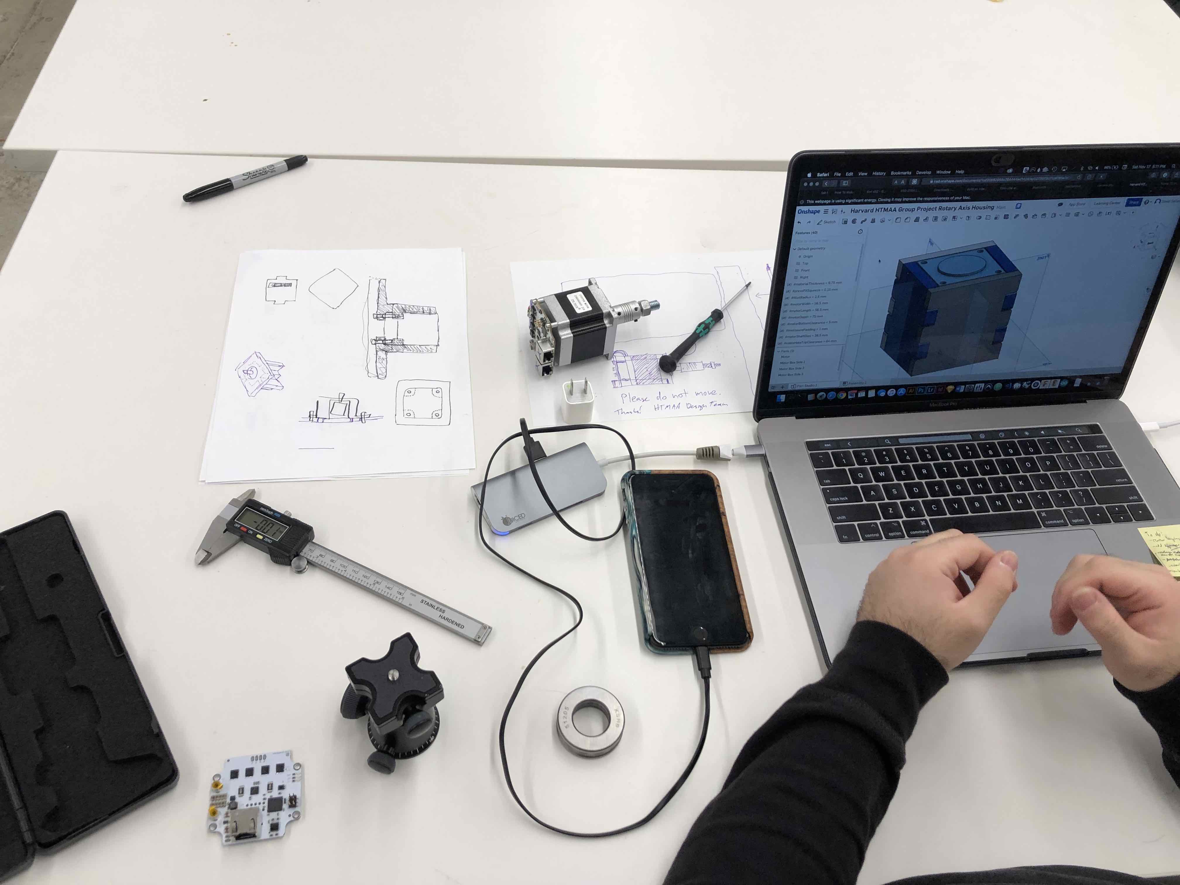
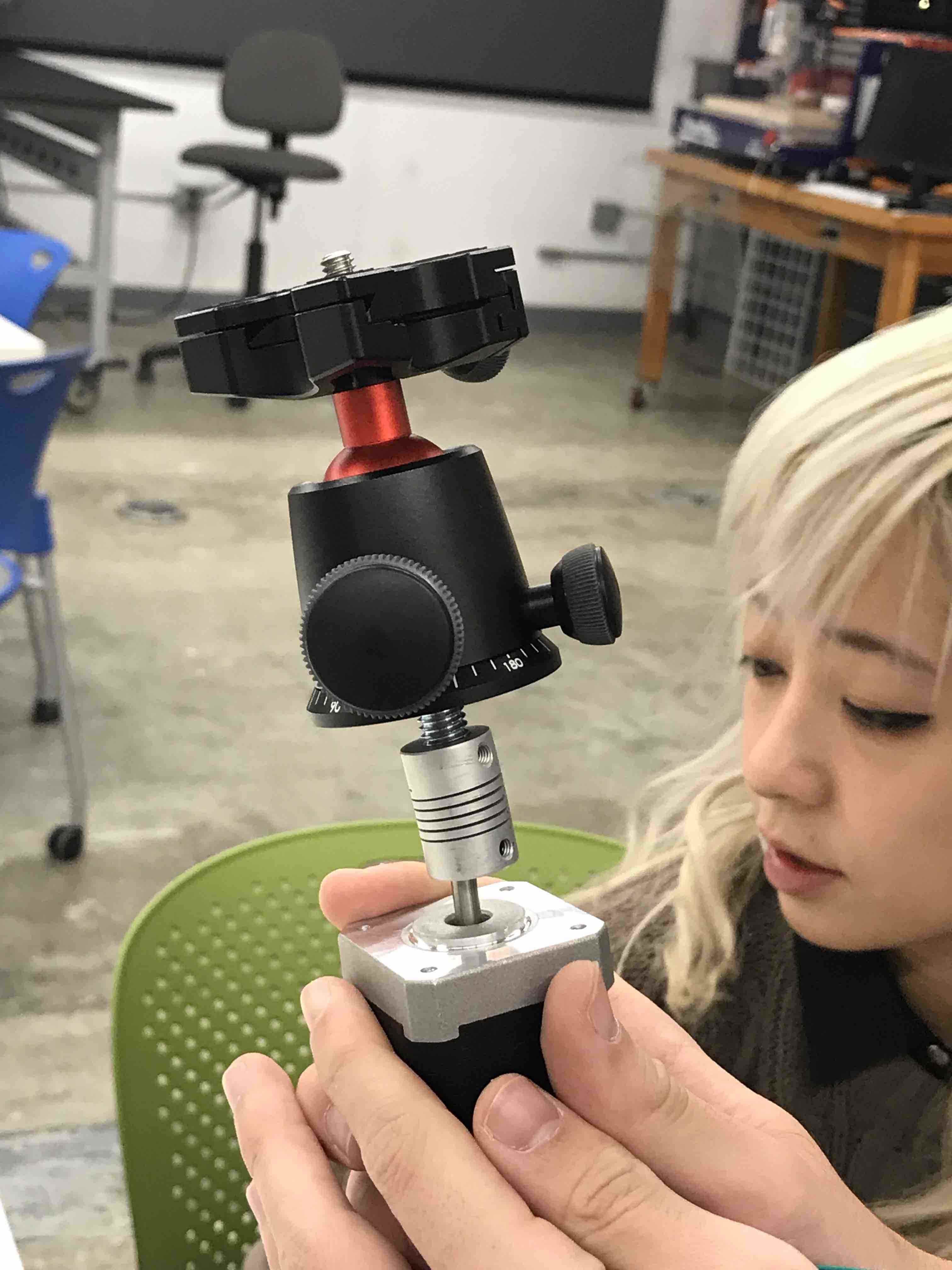
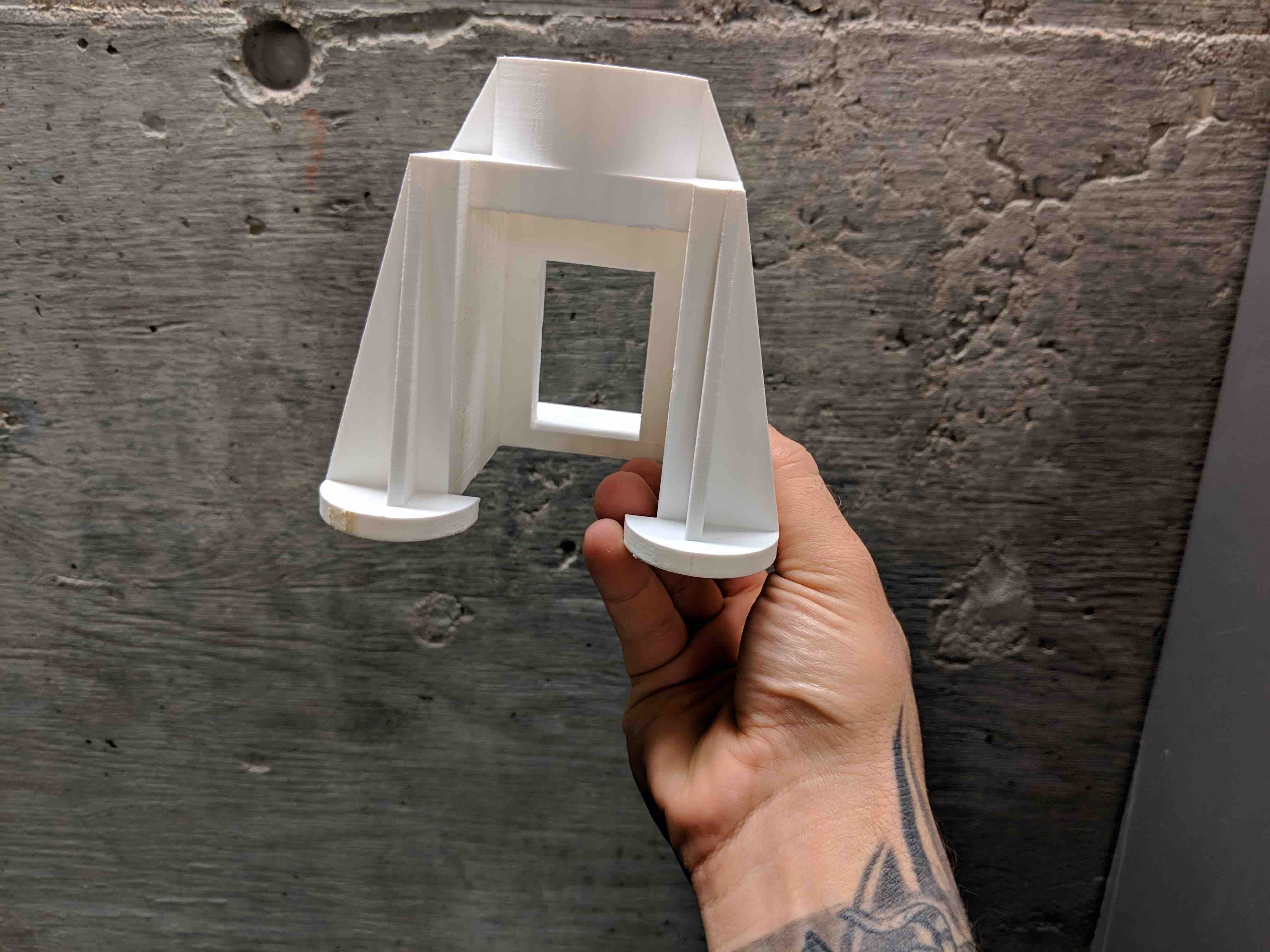
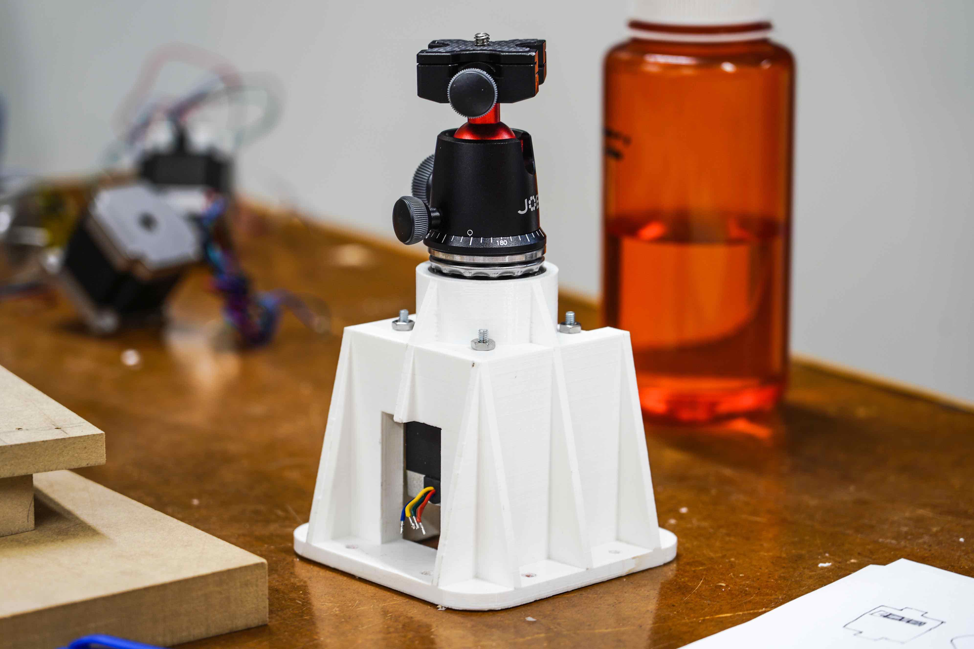
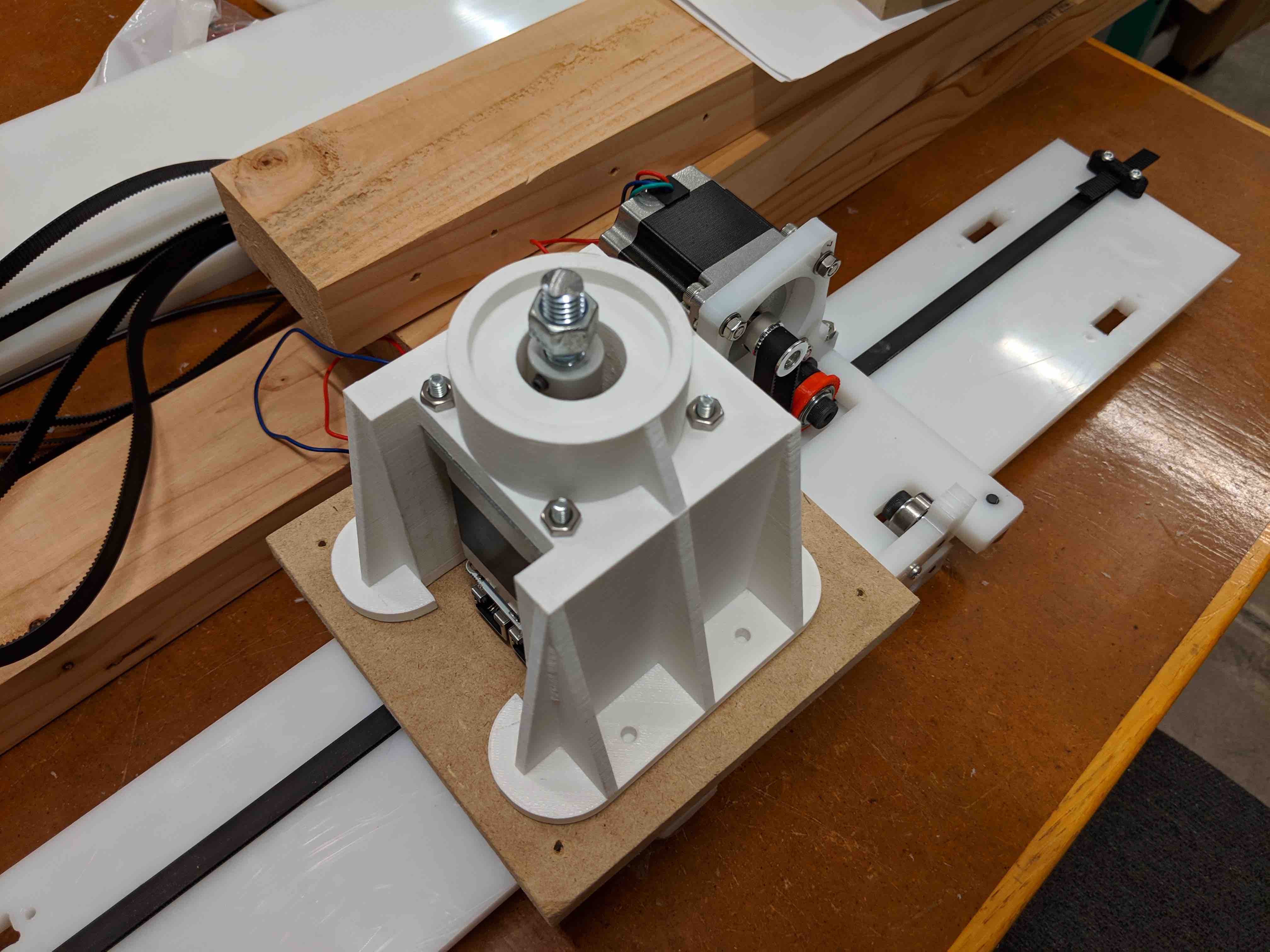
David began work on the rotational axis housing. The plan was to attach a camera mount to the top of the stepper motor using a 14-20” thread and a coupler. The housing would attach to the motor at the top with a recess for a lateral bearing to bear the weight of a DSLR camera.
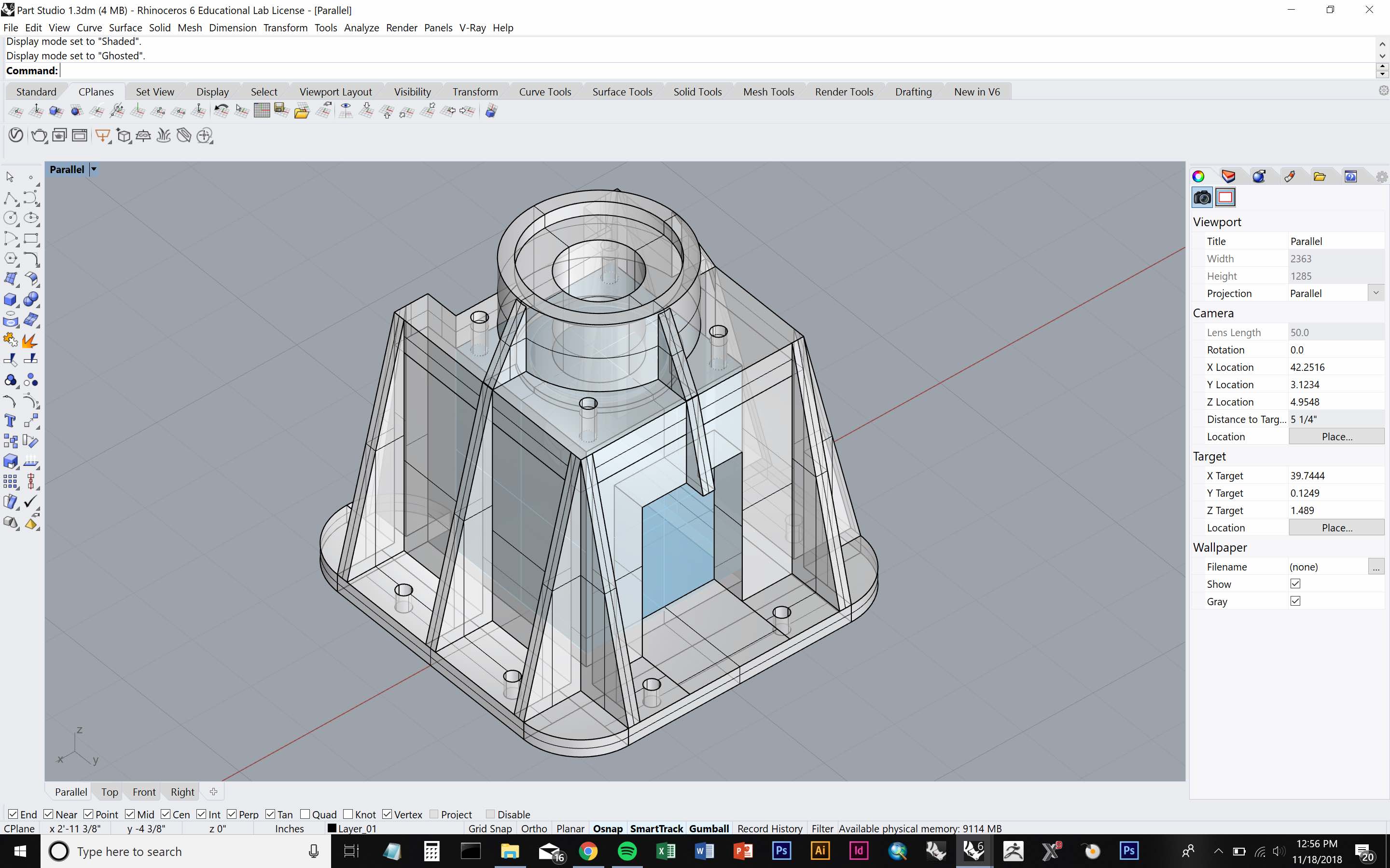
While the initial press-fit design showed promise, David and Sinan switched to a 3D printed housing which would drill to a base rather than requiring press-fit connections, to allow the rotational axis design team and the linear axis design team to work more independently. Plus, the smaller footprint would save space. Sinan imported David’s design into Rhino and quickly modeled the 3D printable housing.
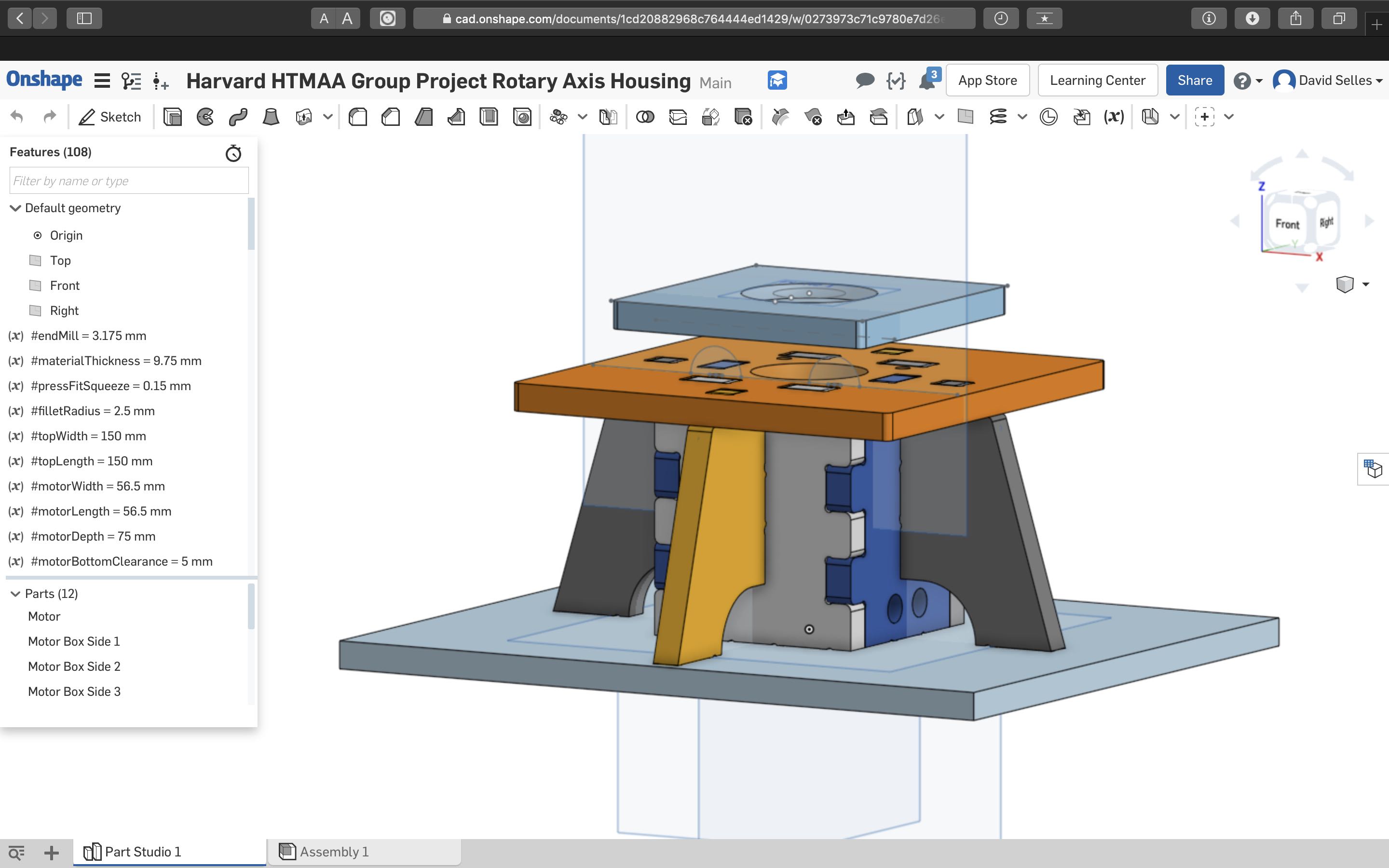
Here is the above link to download:
Overall, this part of the project came out very well.
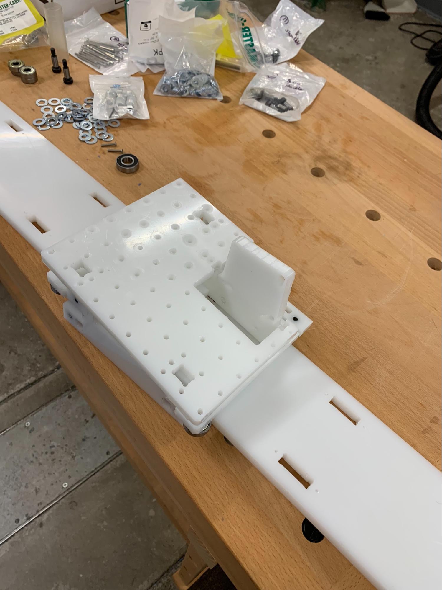
Originally, the design team planned to make the new platform bigger so that it could fit the double width of the axis/rail ain order to mount the rotational motor/platform on top.
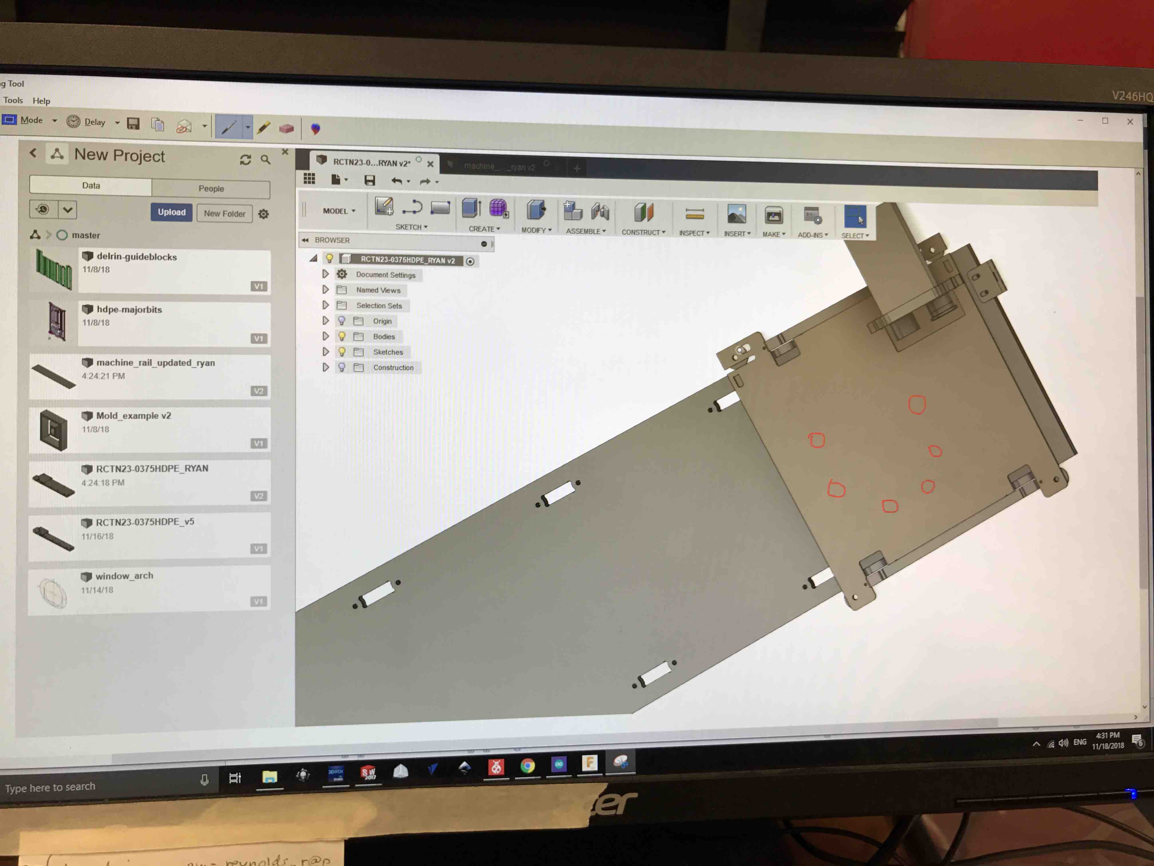
After discussing it with the assembly team, in order to save maximum time on everyone's part, we decided to utilize the axis that was already made on Friday. Instead of rebuilding the entire sliding mechanism, the new plan was to drill holes in the current implementation to add a small wooden offset platform for the camera mount to sit on. This way, we could use the piece we were currently printing AND only re-make the track (which is straightforward and has been discussed with the assembly team).
 F I R M W A R E
C O D I N G
F I R M W A R E
C O D I N G
Jeremy, Jackson, Soumya, Jeffrey, Abdul, Kenneth
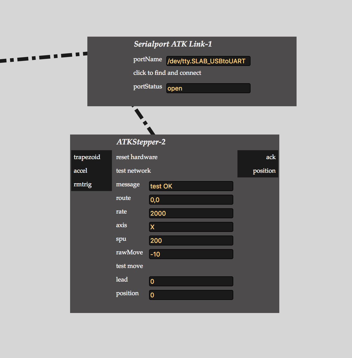
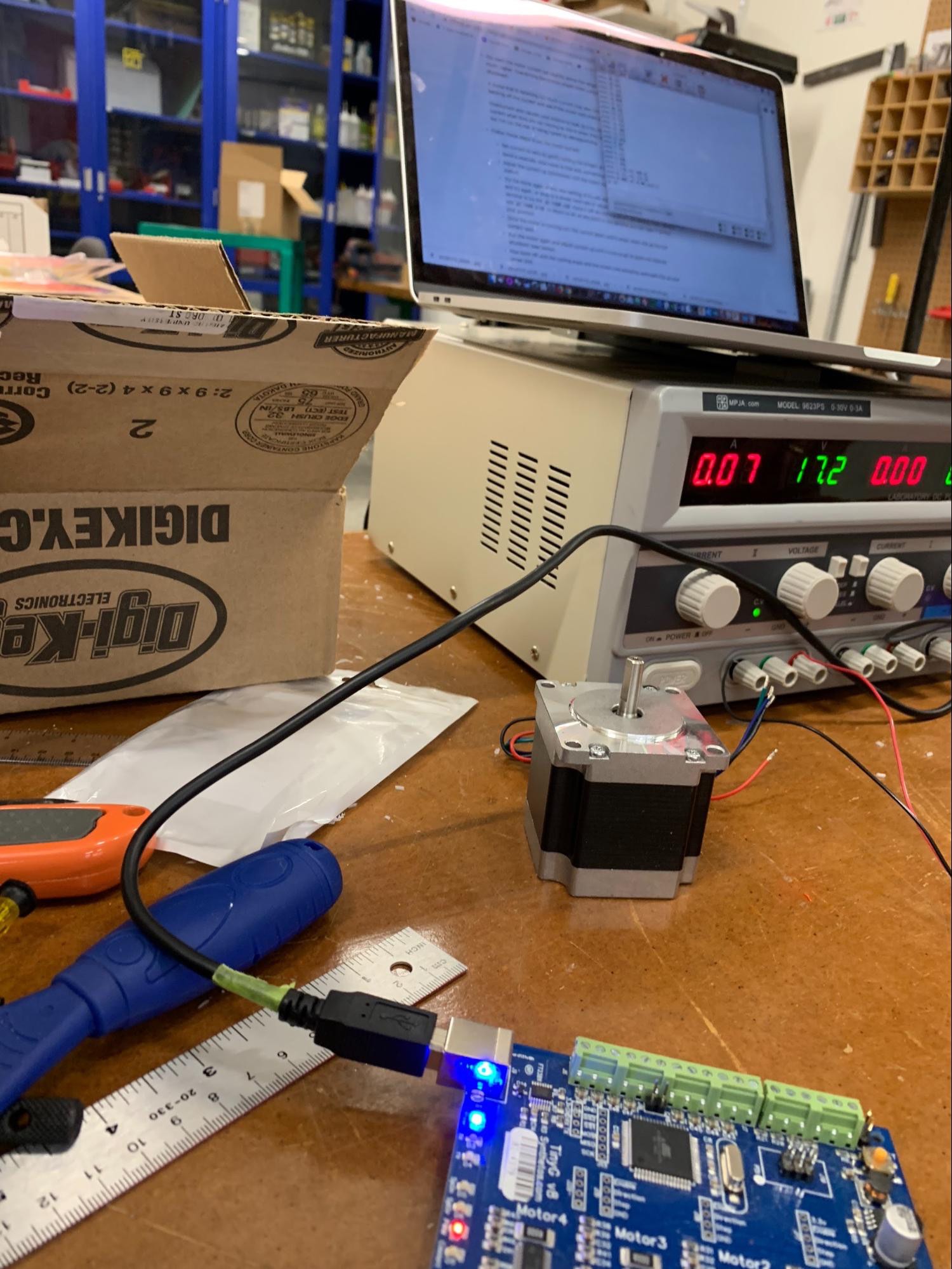
This was the setup that produced a "Test OK" message in RNDMC:
- Router board hooked up to laptop with micro USB cable
- Router board switch set to "pwr rpi" setting (LEDs on board will light up)
- Ethernet-ish cable between router board and stepper board
- Stepper board getting 20V from regulated power supply
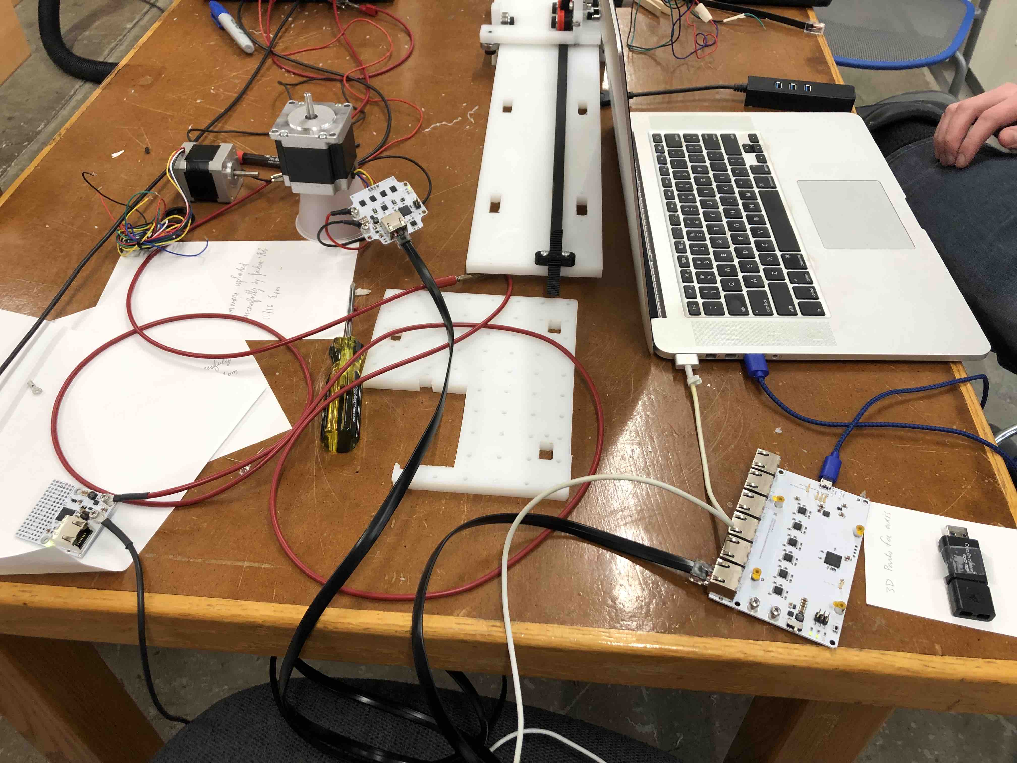
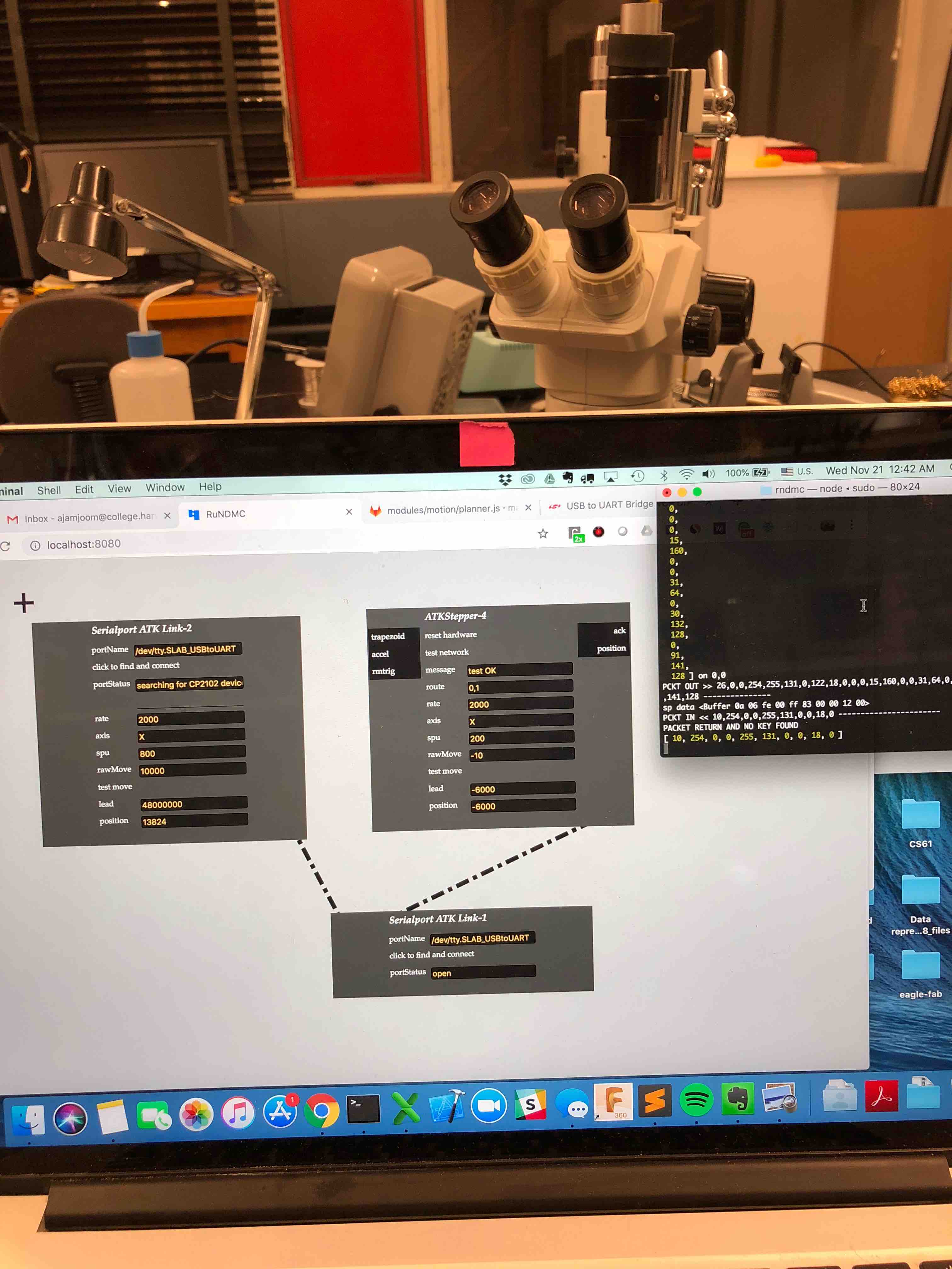
Unfortunately, the tests were inconsistent. Below is documentation during the trouble shooting phase:
The issue is that when you start up RNDMC, open up an atkstepper module, and click "test connection" (or something to that effect), the command line spits out an "ERR: port not writable" error. According to Jake's response to the issue that Jeremy created on gitlab (https://gitlab.cba.mit.edu/classes/863.18/site/issues/69), this error is issued by atkseriallink.js in the modules/hardware directory. It prints the error if an object called 'serialport' is null or if it can't be written to, so I've been trying to track down how serialport is instantiated and why it would be null.
I think we have a lead on what's causing the inconsistent behavior (in terms of sending a packet and not getting a reply) in the router - when we click the tiny reset button on the board and try the network test again, everything works fine. When we unplug the board (turning it off), plug it back in, and try the network test, it sends a packet out but never gets one back. Pushing the reset button fixes this. We suspect that the reset button pulls a specific pin high or low on the router's XMEGA, and that turning the router off by unplugging it (not that there's any other way to turn it off...) leaves that pin floating instead of letting it go back to the state the firmware expects it to be in.
The bottom line is that we can now consistently connect to the serial port and get a successful network test, and we've characterized to some extent the circumstances which cause problems and how we can fix those.
One weird thing to note is that one of our atkstepper23 boards sometimes emits a hissing noise when we power it at 24V. Turning the voltage down to ~12 and then back up to 24V fixes this, for some reason. Does anyone know what might cause something like this to happen? It's probably a question for Rob really.
An additional point about getting RNDMC talking to the endpoints - we achieved consistent communication by creating a seriallink module first, clicking “click to find and connect” and waiting for that to finish, THEN creating other modules (atkstepper, atkbreadboard) and clicking the network test button on those modules. Doing it any other way seems to result in RNDMC not creating the serial port as expected and shooting itself in the foot.
Note that with the help of Jake, we realized that the hissing sound is actually a good thing - it is a sign of regulation of coils that is supposed to happen
Another note is that during our intial stepper programming phase, the issue we ran into was that our board was bad - we tried to do many types of debugging including manual input of various connections, but there was no luck. This is documented in detail here. Interfacing with Motors:
We utilized Jake’s RNDMC user interface and code to program the rig to function as follows
- User clicks start button
- Linear motor moves from start to end and then end to start
- Rotational motor moves the camera 60 degrees in one direction, then 60 degrees in the other direction
 Making a cable to connect boards...
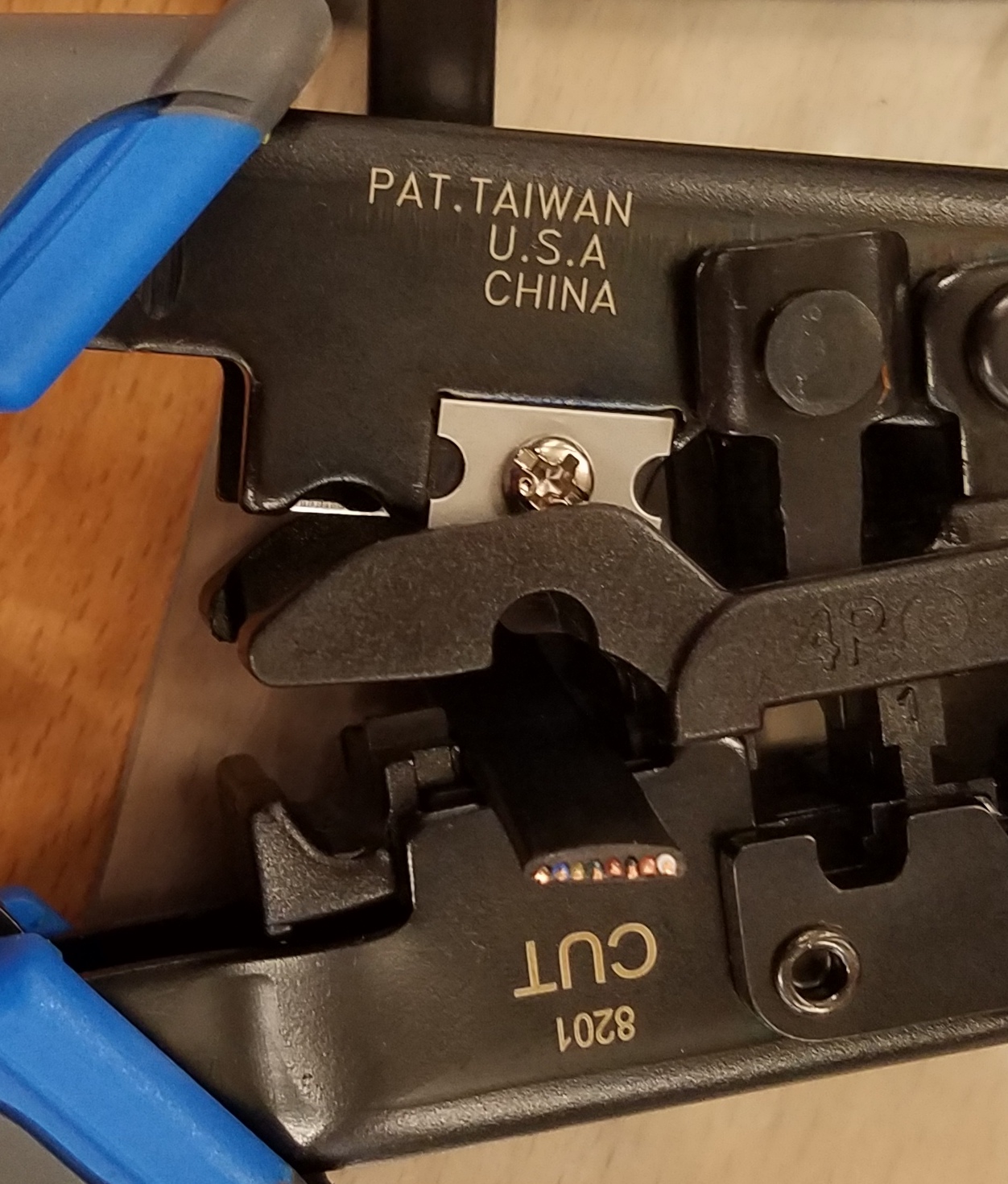
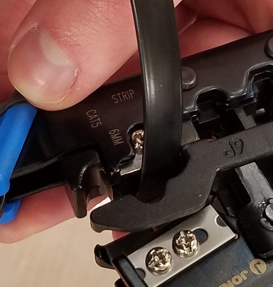
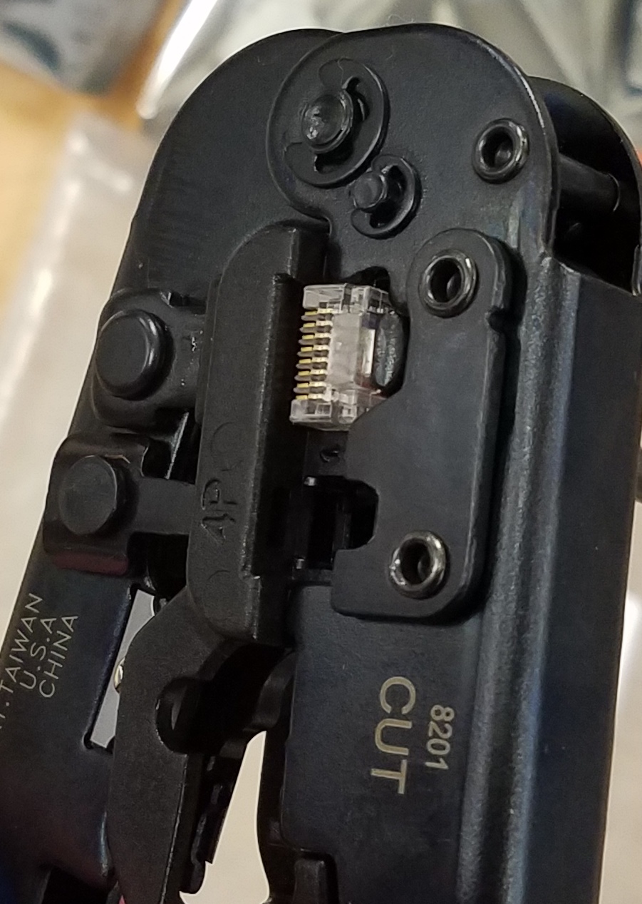
- Use the flat cable, the ethernet-like endings and the big crimping tool
- Put the flat cable through the crimper in the opening with the blades. The side labelled “cut” cuts, and “strip” strips. You want them both to be doing their thing
- Grip the crimper closed, hold it tight, and pull the cable out from the "strip" end. It should come out with the colored wires under the black casing exposed, but not stripped.
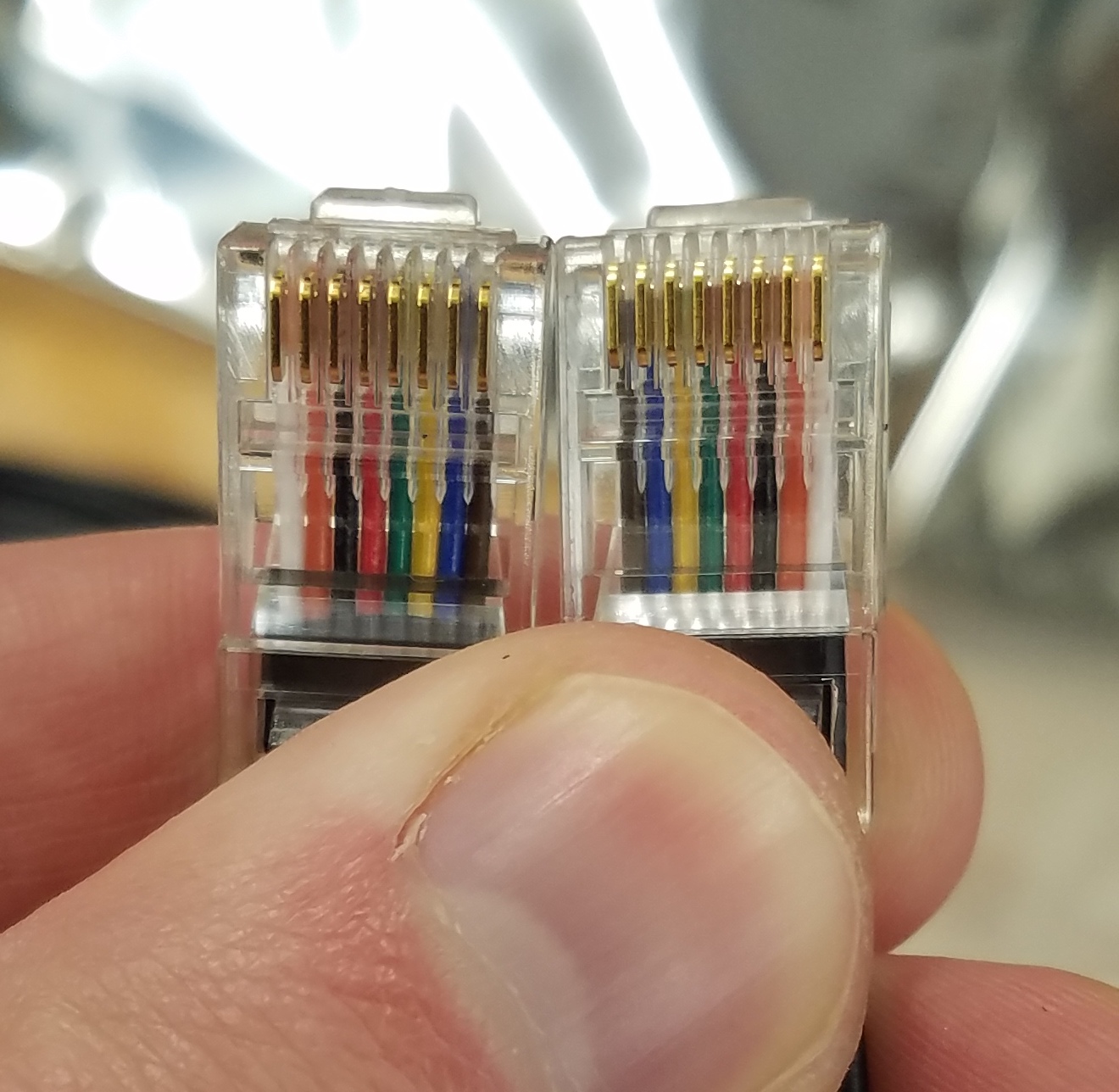
- Slide the wires into the housing for the ethernet cable. The orientation for the first one doesn't matter, but when you hold both ends up next to each other, they should be reversed, like this:
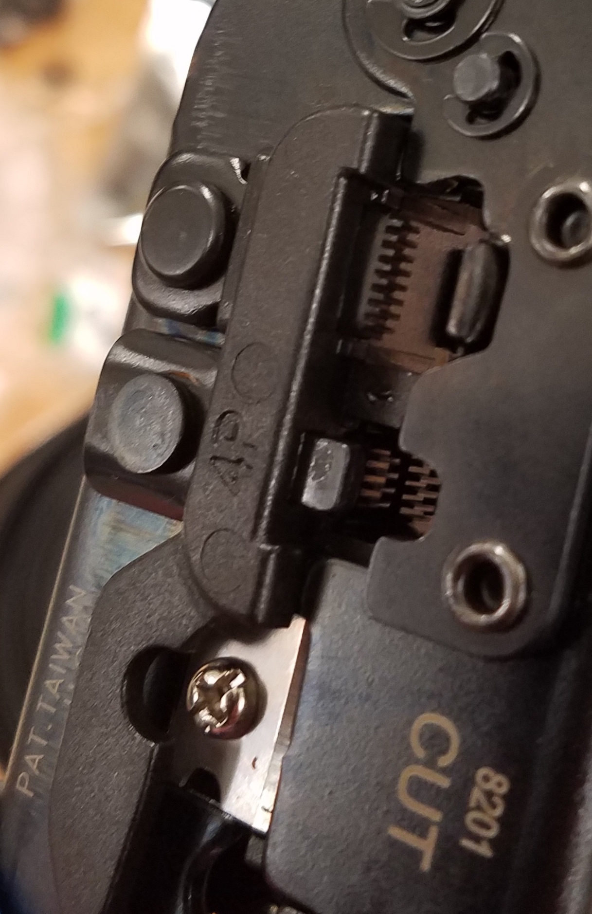
- To crimp the end, first figure out which direction to put it in. The end should go on the side that says "CUT", where there is a comb-like thing in the crimper:
- The wire end should be on the opposite side, where there is a flat piece inside the crimper:
- With the end in place, just close the crimper tightly and release, and the end should be connected. Repeat the process for the other end, making sure that the colors are reversed inside the housing
CODING UPDATE TO BE CONTINUED
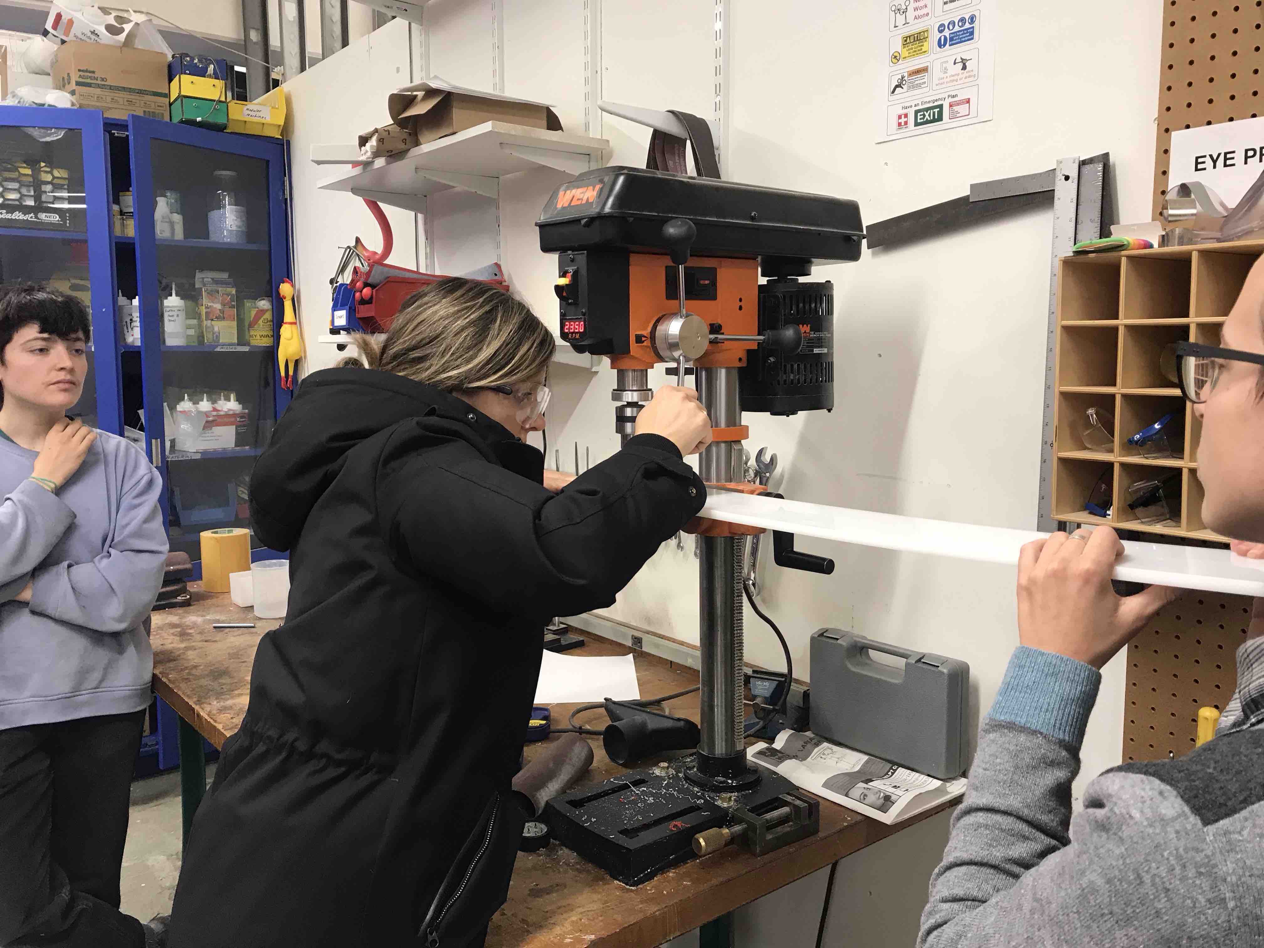
A S S E M B L Y Kate, Nicki, Nicole, Hannah, and ZariaThe Harvard section utilized Jake Read’s kit to begin construction on a machine which could create a 360-degree panorama/timelapse by utilizing three unique axis. To get started we laser cut the components and 3D printed the parts from Jake’s GIT (https://gitlab.cba.mit.edu/jakeread/machineweek-2018). The post-process work to prepare for assembly was relatively extensive. After laser cutting the components in HDPE we had to cut them out from the board and use an exacto knife to trim off the excess material. For the individual holes we utilized a drill press to clear out the individual channels on each of the components. The laser cut could have been slightly stronger, or slower, in order to ensure the pieces were fully cut, to include the holes. After finishing the cuts, as well as the 3D components, an inventory of the supply box was completed.
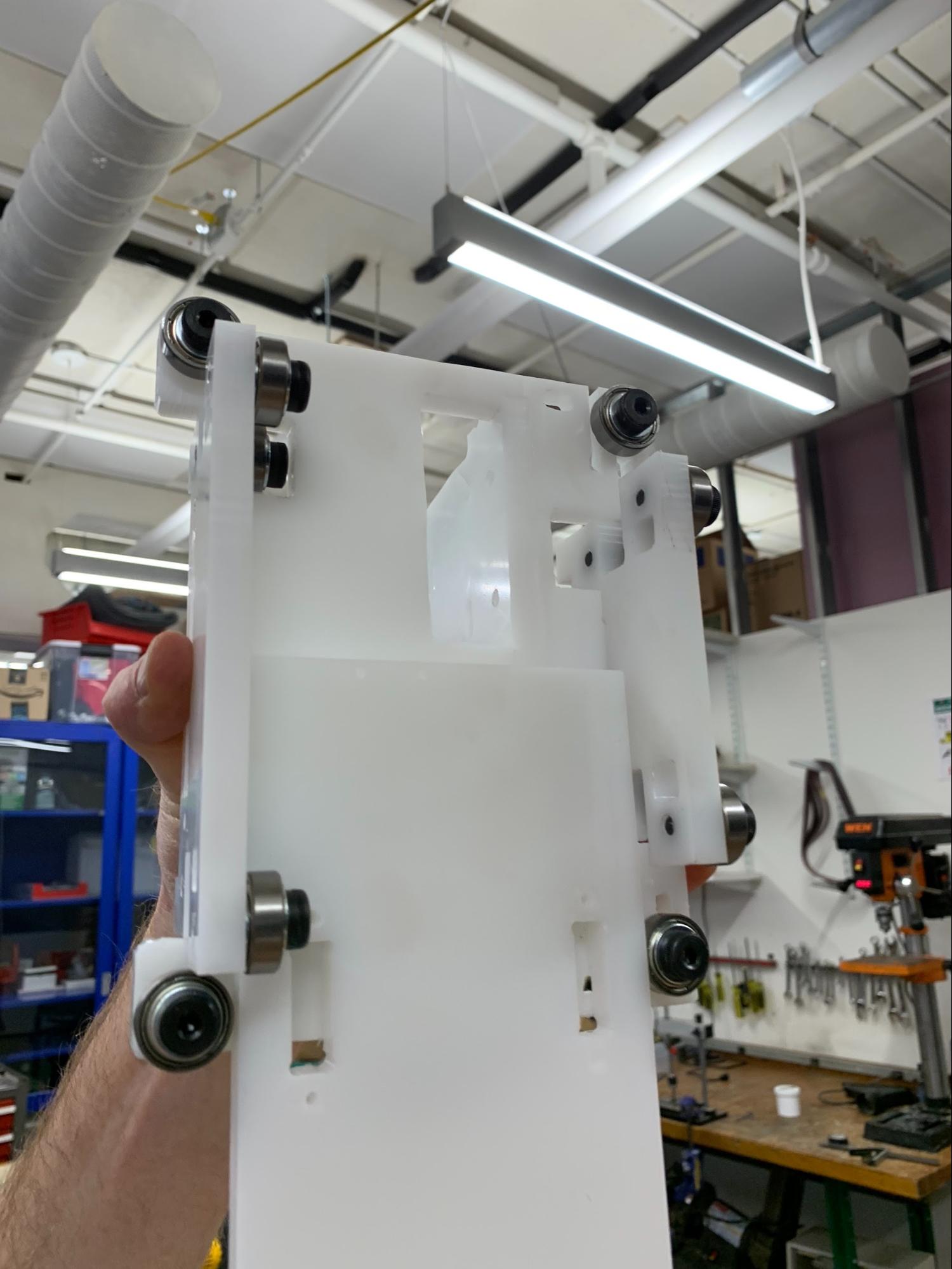
Organization of the components began by utilizing the Assembly sketch. We started by assembling the ‘Preload stacks’, the ‘2x Belt Guide Stack’, the ‘12x Guide Stack’, as well as the hardware and belt components. Ensuring the stacks are accurate is critical for the fit of the gantry to the rail.
Prior to screwing in the stacks to the HDPE the holes had to be punched for threads. This was simple, but proved difficult in that the HDPE was soft enough that too much stress when screwing the stack into the board easily stripped the punched hole.
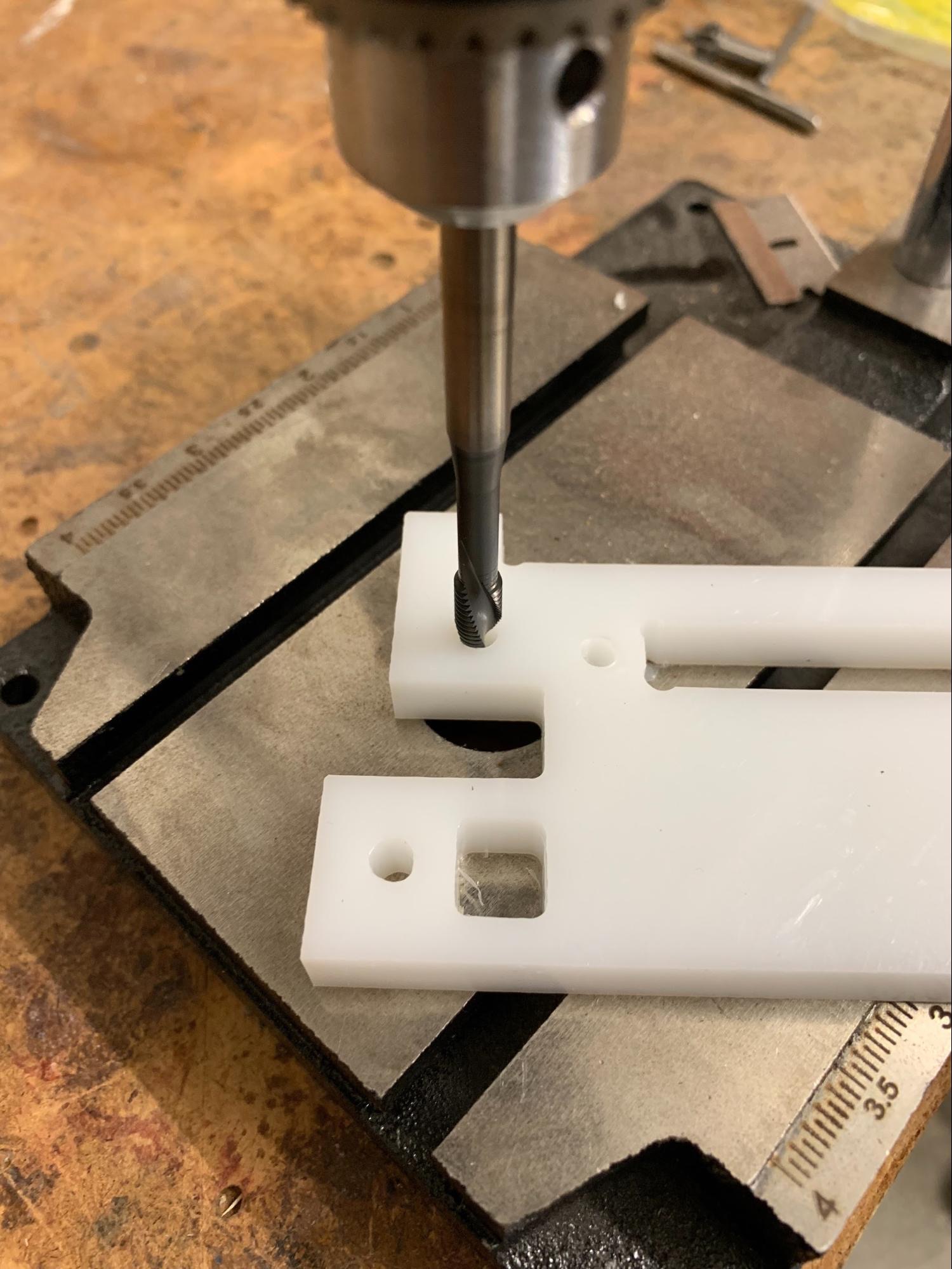
Attention to orientation on the schematic is critical, we initially incorporated the motor and bolts opposite to what was required, which is how we discovered that tapped holes are easily stripped when using HDPE. After attaching the stacks, we began work on the belt.
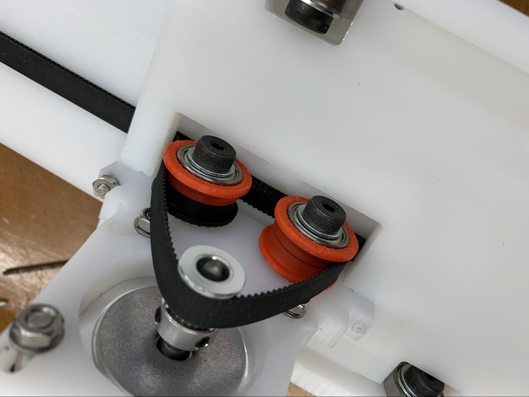
The belt is tricky. The 3D printed pieces require some filing in order to fit the two pieces of the belt through. We started by attaching the simple stacker block and then attached the motor componentry and then worked on the more robust end piece. Sliding the two pieces together, with the teeth aligned, required significant filing of the pieces as well as an attention to detail and four hands when sliding and tightening the track through the 3D printed piece. Of note, we are not entirely sure why there are two separate types of connectors for the belt when they both secure the belt in place. Holding the belt tight while then screwing the 3D component to the board is definitely a 2-3 (wo)man operation. It is important to note that prior to tightening the belt down, make sure the belt is thread correctly around the individual guide stacks and motor rotary.
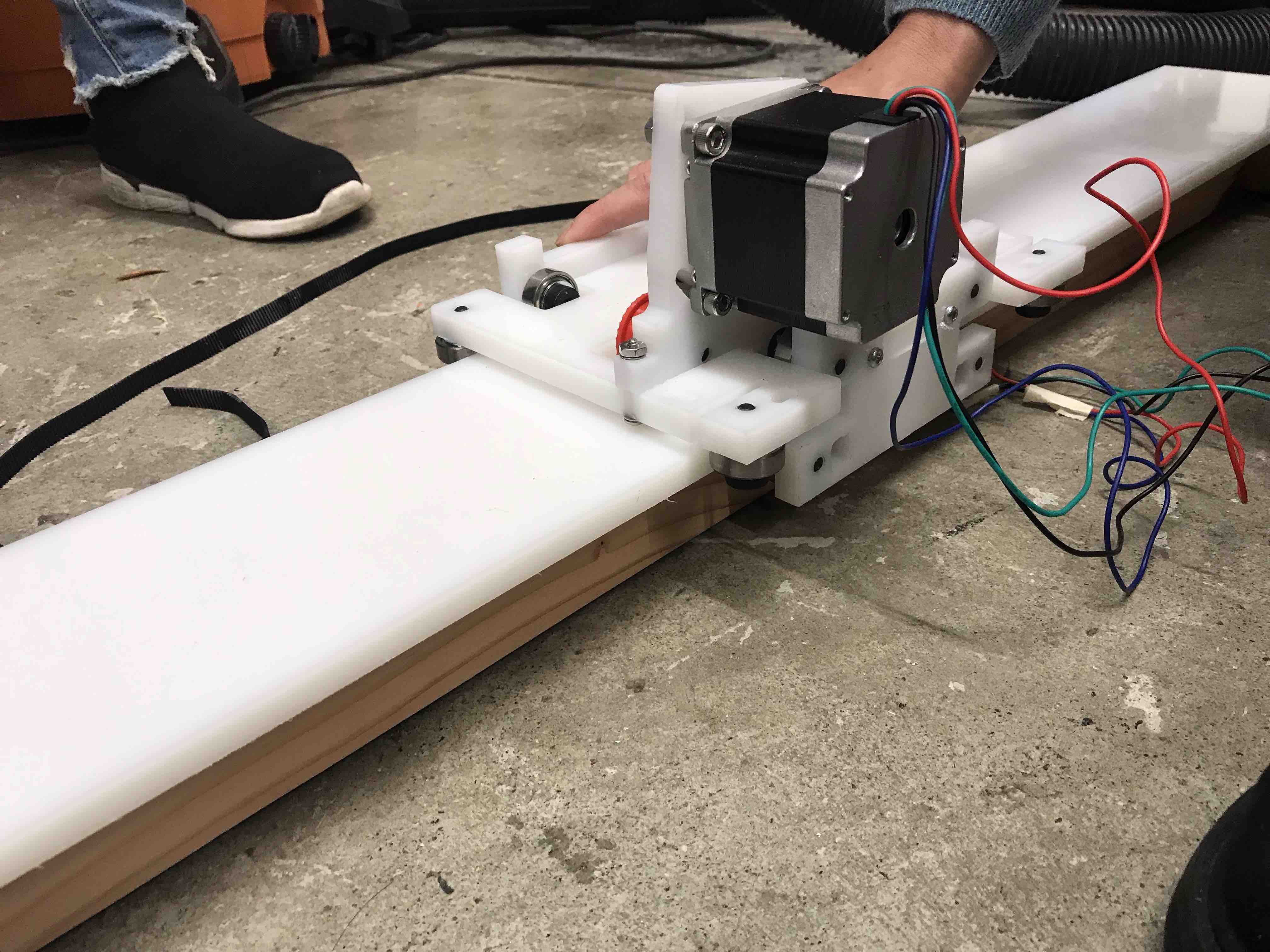
We tested the motor prior to attaching it to the gantry, then established the TinyG four motor board on the machine set-up. We connected the board to power MPJA and the motor to the Motor 1 connection.
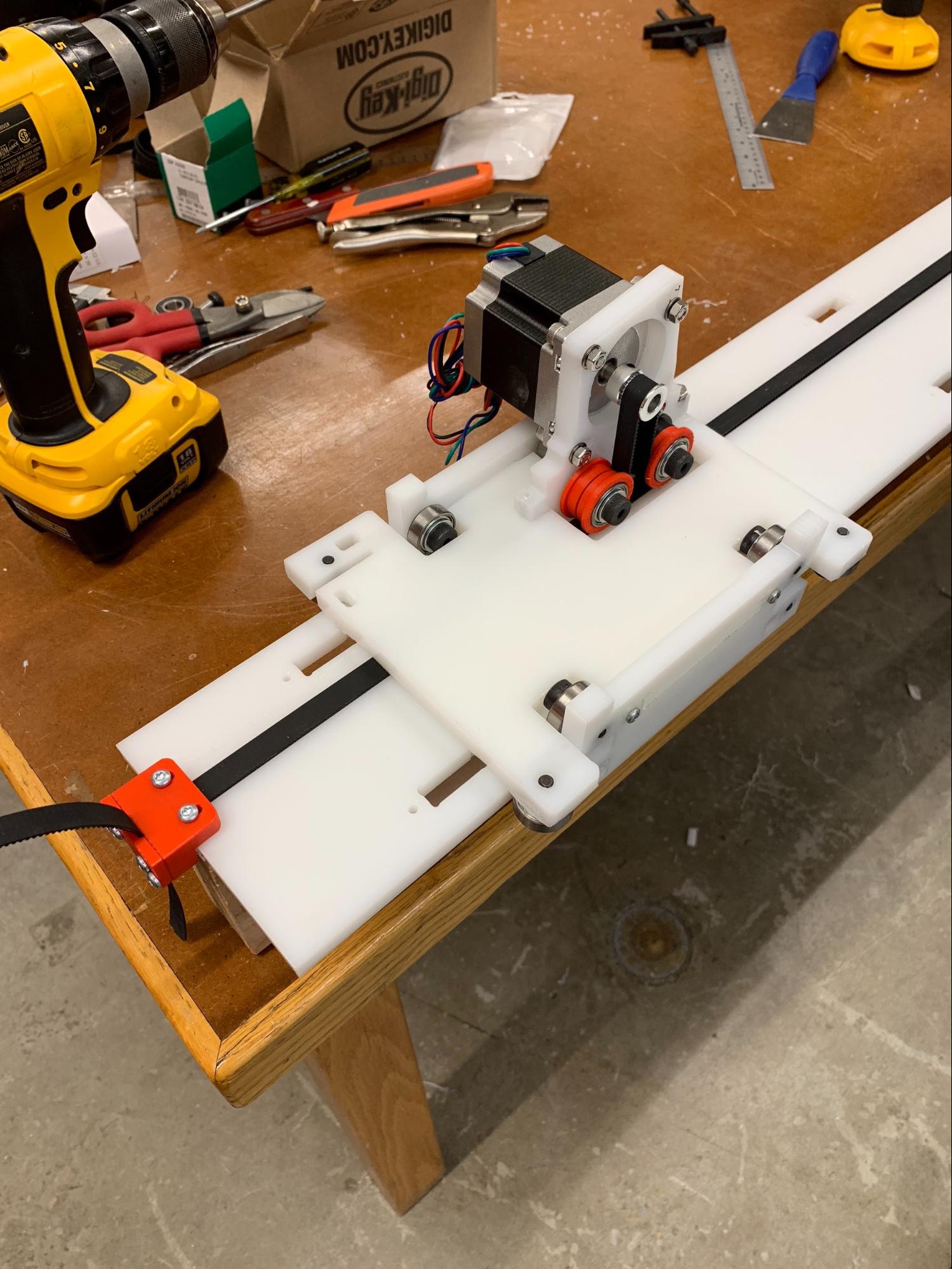 Final assembly was hindered by a fit issue of the gantry to the primary track. The gantry was approximately 5mm too narrow for fitting the track. Options include recutting the pieces or milling out 2.5mm per side of the HDPE. To finalize the set-up we attached the track and gantry to a 2x4 with no problem. The gantry runs very smoothly with minimal friction along the track. The motor requires machining a fit component for the spindle in order to securely have the belt run (Rob was in work on this Friday evening).
Lessons Learned:
- Precision matters, Jake’s kit is amazing and the detail in component measurements is quite surreal, that being said, assembly requires precision to ensure the pieces all fit together. The schematic is essential and verifying part nomenclature is essential.
- Post-processing is key prior to assembly. Shaving off excess material, drilling out holes, tapping holes, filing 3D components, and more are all necessary for assembly. Measure twice, cut once.
- The belt is finicky and takes patience and four hands. Leave time for this.
- HDPE holes are easily stripped, be prepped to use a washer/bolt to secure components in place.
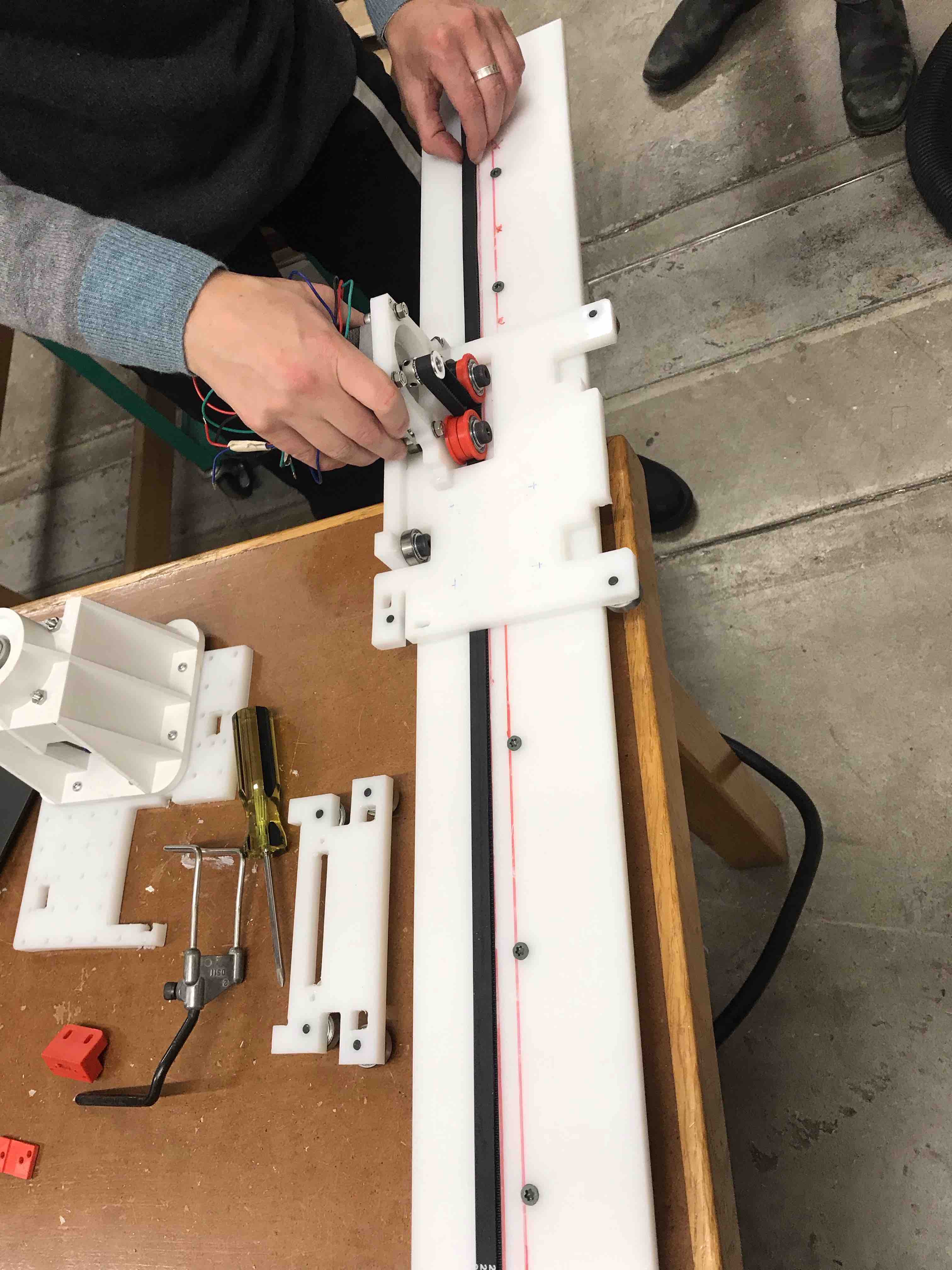
After the design meeting, we decided to make a longer track. We used the original rail as a guide to create the track mounting holes and cut a 2x4 as the base. We had to find some wood screws long enough to get a good grip on the wood - luckily there were plenty. We found the center point of the 2x4 and HDPE rail, and lined those up so that there would be enough clearance for the trolley bolts.
The trolley required some real modifications, since the 3D camera mount had to be secured to the platform, and there was an issue with stripped components from the first assembly. We removed some material from the bottom of the platform to make way for a nut/bolt situation, and had to be conscientious about where the holes for the camera mount could go.
Kate had some good advice for us regarding the belt mounting process, and as a result we were able to quickly adjust the belt to the appropriate tautness.
On testing the movement, we discovered a slight warp in the board - juuuuust enough to interfere with the smooth running of the trolley. We un-mounted the rail, adjusted, and re-mounted, and now it moves freely.
 C A M E R A C O N T R O L
Lara, Victoria, Jasmine
With help from: David Selles, Lins Derry, Jeffrey Wang and Abdul Jamjoom
Camera goals for the 360-degree panorama/timelapse machine
The user adjusts the desired settings (video versus picture sequence, timelapse duration, shutter speed, brightness etc...) in the code, from where on the machine takes care of the rest (turning the camera on and off and taking pictures).
Turn the camera on an off using code, rather than using the button on the camera to manually turn the camera on and off. Use code to have the machine automatically focus and release the shutter. Automatically save the pictures in the same folder on the computer, thereby eliminating the need to transfer the images from the camera manually.
Helpful websites to get started
EOS Utility: a free software application that can control Canon cameras when tethered to a computer.
Arduino to take a picture every x seconds for y minutes. For our machine application we would not need the buttons to change the settings. Instead, the user would alter the settings in the software.
Examples integrating Arduino and a shutter release cable: here and here.
The use of a jack connector to control the camera's shutter and focus.
Using an eyefi SD card to wirelessly, automatically, and in real-time transfer the pictures from the camera to the computer.
Build your own camera using TTL Serial camera: TTL serial camera, WiFi Arcuino-cam, OV7670 camera module with Arduino and VC0706 camera module with Arduino.
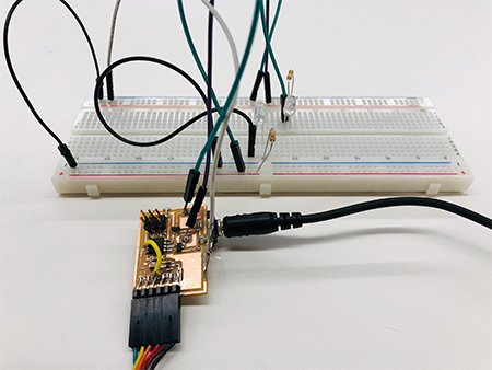
Jack connector and board design
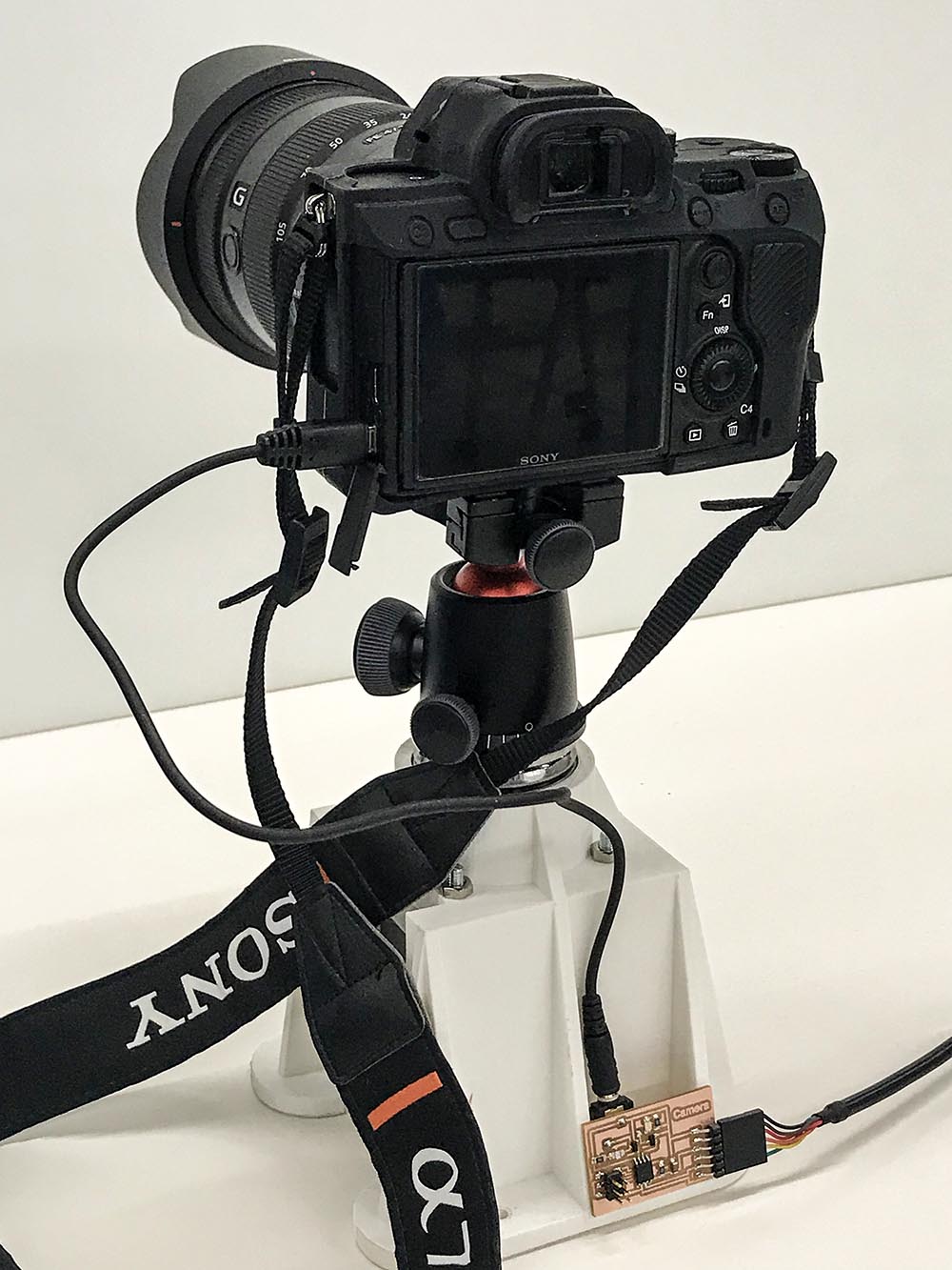
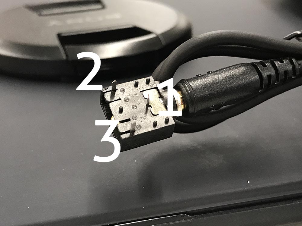
The focus and shutter triggers can be controlled "outside of the camera" using a cable and a jack connector. David and Lins figured out how to use a jack connector. A 3.5 mm female jack has thee pads, numbered 1, 2, and 3, in the pciture. A connection between pad 1 and pad 2 will focus the camera. A connection between pad 1 and pad 2 AND pad 1 and pad 3 will trigger the shutter (e.g. take a picture). Good practice is to first focus the camera and then take a picture.
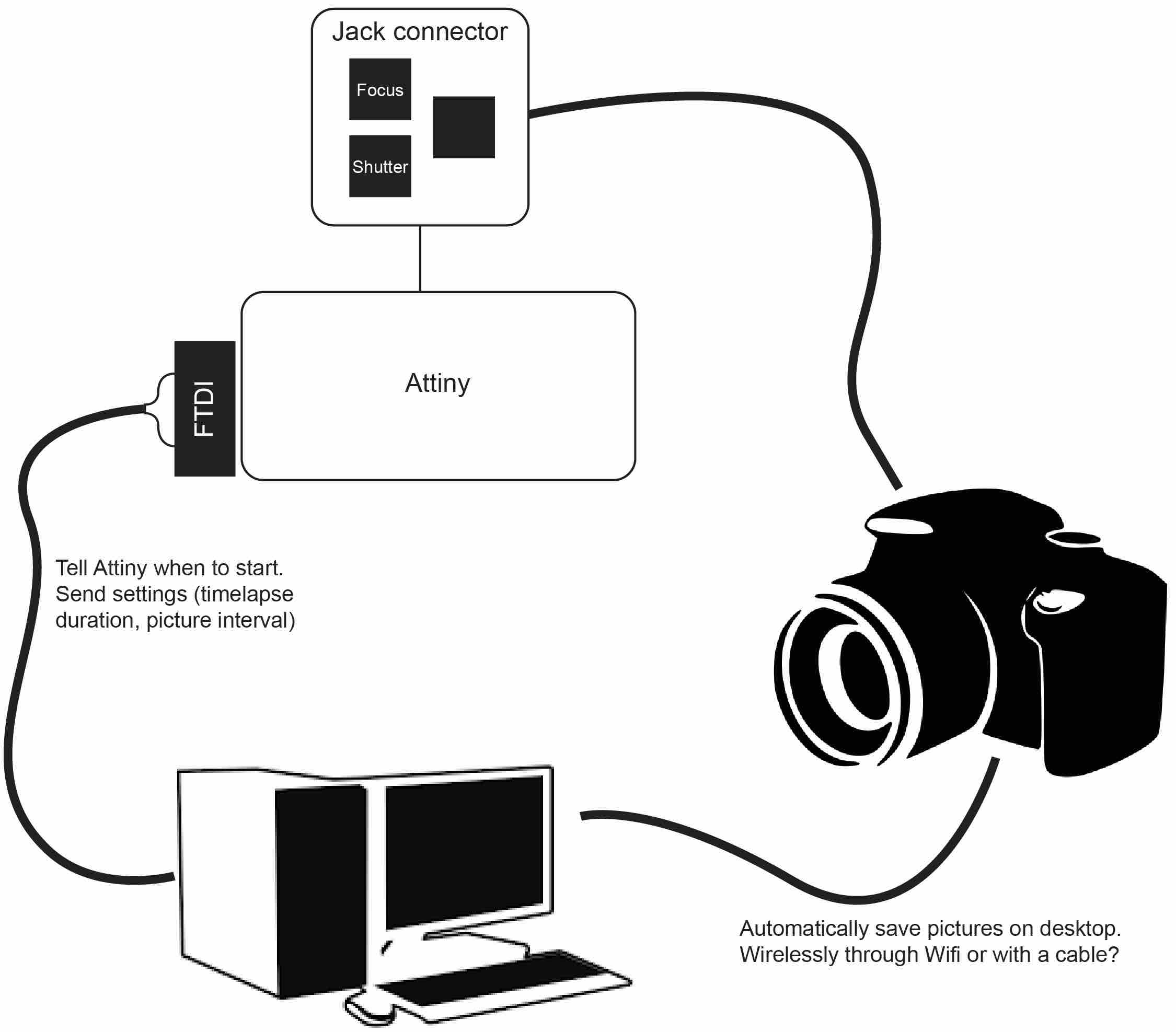
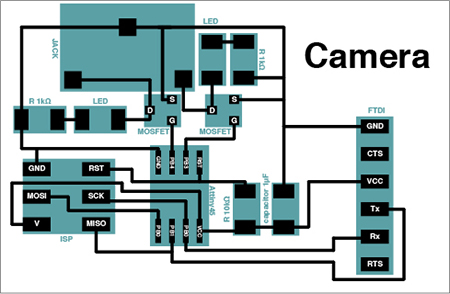
 To control these connections we designed a PCB board including an Attiny45, mosfets to regulate the connection between the pads on the jack, and an FTDI connection to both send and receive information. The board needs to receive information on the timelapse duration and picture interval set by the user of the machine and will send out information regarding the status of the camera (e.g. if the timelapse has started, finished, the number of the latest picture it has taken etc...)
In the process we adjusted mistakes in the board design and added LEDs to test the performance of the mosfets.
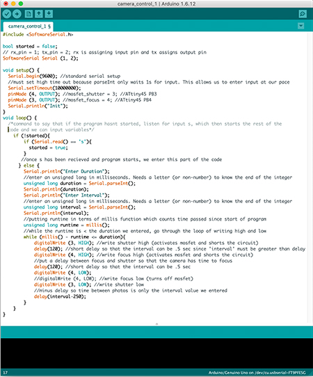
Programming
The main issues we experienced during the programming of our board were space issues (the sketch often used too much program space and global variables used too much of the dynamic memory, preventing us from uploading the sketch) and getting the serial to work in the way we wanted to communicate with it (entering a sequence of values and storing those values for the code to use). Jeffrey and Abdul came to the rescue and helped me and Jasmine to get the Serial to perform in the way we wanted it to and reduce space. To solve the space issue, we avoided using Serial.readString() and print statements are short and sparse (e.g. "Init", "D", "I", etc..)
To get the shutter (pin 3 on the jack connector) to work properly, by trial and error Jasmine found out we had to activate the mosfet for the shutter first in order to achieve the voltage drop necessary.
New board
After verification that the board worked seamlessly with the code, Lara made a new board to fix earlier mistakes and added LEDs for visual indications on the performance of the mosfets.
P R O J E C T M A N A G E M E N T
D O C U M E N T A T I O N
Lins
Communication was at the core of this role. To facilitate a lot of it, we used the Slack app, Gitlab Issue tracker, Google Docs, email, and occasional personal texts. On Slack, we set up independent team channels and a general one for all. Throughout the day, I followed all channel activity, communicating key issues or milestones between the teams as needed. When I noticed teams not communicating next steps or arranging meetups, I would push and prod a bit, normally repeating my messages over Slack, Issues, and email, until new activity got stirred up.
The Google Doc served as a temporary repository from which I created the final group page on Gitlab. Many added detailed updates and pics to Slack which I easily moved over to our shared “Documentation of Progress” Google Doc. And others, went the extra distance and updated the document directly. For those more sluggish with documentation I found writing personal messages or small group messages requesting updates to be most effective.
After downloading and resizing pics from Slack, the Google Doc, and email, and making sure each team was at least 50% up to date on the Google Doc, I assembled everything on Visual Studio Code using the html template I’ve been using on my personal fab lab site. In Gitlab, under the Harvard site repository, Rob set up a machine week folder for me to populate. There, I added all the appropriate style sheets, images, and html index. Then, on the morning of class, I did a final sweep of Slack and the Goggle Doc for last minute updates to be added to the group page. Et voila!