#01 Final Project - jamBot
jamBot - Draw

Introduction
Welcome to my final project. My name is Abdul Jamjoom and below is my full documentation on how I built a robot that draws cool things with a pen. My journey was long and by going through my documentation you will see some of the things I built and hacked to get his robot to move and draw. It was an amazing experience working on jamBot and I am confident that I will keep extending this project and making it even better!
Documentation Outline:
- MasterPiece Q/A
- General Concept
- Initial Plan
- Main Components I bought/rented
- Building the wheels - assembly and crafts
- Fabricating the Body - laser cutting and 3D printing
- PCB - electronic design and fabrication
- Putting things together - networks and assembly
- Pen Rig - 3D printing, crafts, and assembly
- Programming - networks
- Final Product
- Files
1 - MasterPiece Q/A
What does it do?
I built a robot that draws images with a pen. The user can move the pen up/down and can also move the robot in four directions
Who’s done what beforehand?
I got inspired by RoboCup’s design and built off of that
What did you design?
- servo PCB
- slightly edited Niel’s unipolar stepper motor PCB
- jamBot shell - laser cut
- jamBot columns - 3D printed
- pen rig - some parts were 3D printed others were hand crafted
- network of motherboard communicating to 5 slave boards
Materials
- 1m x 1m recycled clear acrylic - FREE as it was second hand use
- some PLA for 3D printing - harvard fablab
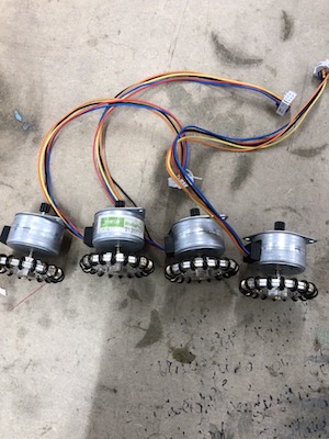
- 5 unipolar stepper Motors - harvard fablab
- 4 Omni directional wheels - rented them from the harvard robotics team for free
- A bunch of screws - harvard fablab
- Springs - harvard fablab
- Zip-ties - harvard fablab
- 2 table tennis balls - my own
What parts and systems were made?
- 2 robot’s shell - laser cut
- 4 shell columns - 3D printed
- 1 servo PCB - milled
- 5 stepper motor PCB - milled
- network between 1 mother board and 5 boards - user interface and programming
- 1 touchpad
- 1 touchpad PCB
- 2 bluetooth PCB
What processes were used?
- programming
- user interface
- laser cutting
- milling
- 3D printing
- input devices - user input from a touch pad
- output devices - 5 stepper motors and a servo
- networks - bluetooth and serial bus
What questions were answered?
- How can you build a scalable and modular system? the modularity of my design was crucial to its success
- How can you network between multiple devices all at once? I had 5 motors all running at the same time and needed to know what’s going on where
- How to increase the accuracy of a drawing? my robot does a decent job, but I need to use smoother wheels and smaller step stepper motors to get better resolution
- is it possible to create a device that draws/mills/3D prints without being restricted to space? I think so, this project showed that it’s possible to draw with no container limits such as 3D printers. The next step would be to make the head modular such that the robot can do several tasks than just drawing
How was it evaluated?
I wanted the robot to take user input and draw something. jamBot succeeded in doing that, but I would have liked it to be more accurate in drawing. If you scroll to the end you can see a video of jamBot drawing a square!
What are the implications?
I don’t like the space limitation that many of the tools we use have. 3D printers, laser cutters, ShopBots, and many more machines are all restricted with some dimension of work space. I wanted to build a robot that can do similar tasks to the machines we used in class but not be restricted to space limitations. Therefore, I built a robot that can draw and is not restricted by space!
I hope that one day, hopefully soon, I’ll be able to iterate over jamBot and make it modular to the extent where you can simply switch the feeder head and make the robot draw, 3D print, or mill.
2 - General Concept
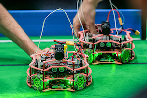
For my final project, I will be designing and fabricating a robot that draws pixelated images with a pen, where the image would be inputted by the user through a touchpad. The inspiration for my robot came from watching a football Junior RoboCup match.
As you can see a above, the robots are small, agile, and smart, this is what I aspire for my robot to be. These robots in the video, however, are more complex than what I need to build as I only want my robot to be able to draw pixelated drawings. This means that my robot will only have to move horizontally and vertically (not diagonally). To this end, my robot will look something similar to the image below.
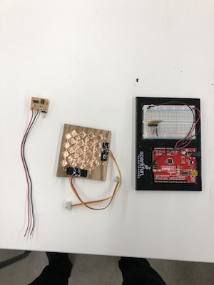
As a starter, I fabricated a board that moves unipolar stepper motors in my output devices week.

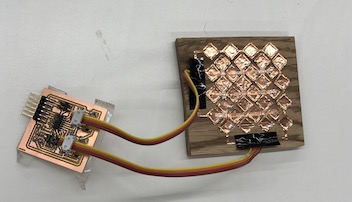
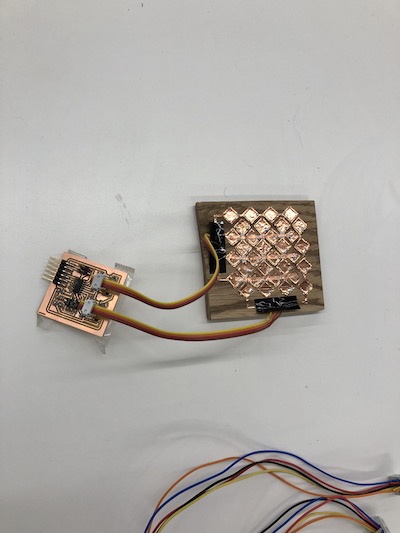
As for the touchpad, I have already fabricated it in my output devices week linked HERE and shown below.
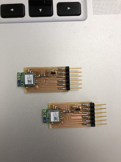
My plan is to make the touchpad communicate to my robot through bluetooth, which I already fabricated in the networking week linked HERE and shown below.
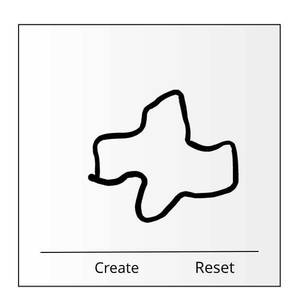
Lastly, I will create a simple interface (shown below), that gives the user the ability to digitally see his touchpad drawing and reset his actions. THIS WILL COUNT FOR MY USER INTERFACE ASSIGNMENT WEEK.
3 - Plan
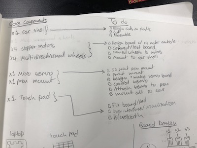
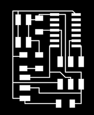
As a starter, I wrote down all the main components I need for fabricating the jamBot (noted as core components in the image below). Additionally, I wrote down on the steps/phases needed to assemble those core components. For example, building the outer cars shell that holds everything together entails designing acrylic laser cuts, cutting the acrylic, and assembling it. You can refer to the image below for the detailed list.
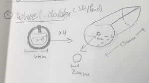
Taking the roboCup robot design as a template, I sketched the components I need to make to build my own robot. The first component is a rod that attaches the Omni wheels to the unipolar steeper motors. The idea here is that the motors rotational shaft is too thing to be directly attached to the wheel, so I have to create a press-fit extension that fits tightly on the wheel and the motors shaft. Below is my initial design.
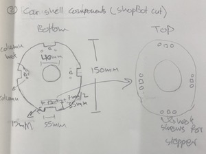
Moving on from the wheels to the jamBot outer shell, I envision laser cutting two layers of acrylic to assemble my robot as shown below.
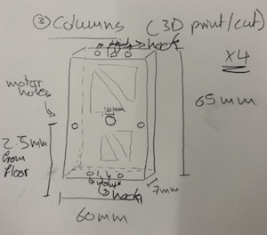
The two robot outer shell planes would be held by four columns that I will be 3D printing. The columns also act as holders for the motors/wheels on the side.
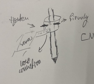
Lastly, I plan to add a pen in the center of the robot that can move in the z-axis so that the robot can draw pixelated objects. My initial design for the pen rig is shown below, but I think i will have to reconsider my design. For now, I plan to use a simple MicroServo to move my pen in the z-axis.
[OLD DESIGN] As for the board, I plan to use two Mega328 boards, one for the jamBot and another for the Touchpad (the touchpad I fabricated earlier for the input devices week is too small).
[OLD DESIGN] Note: S stands for stepper motor [OLD DESIGN] 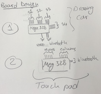
[UPDATE] - I ended up redesigning all the boards and creating a modular robot. Essentially I have one motherboard and 5 slave boards… each motor has a board of it’s own. The motherboard is an arduino nano and all the other boards are PCB’s that I designed and fabricated. Scroll to the PCB and Electronics section for more details.
4 - Main Out of the Box Components
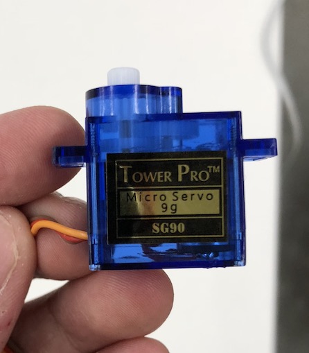
This is the MicroServo that i be using to move the pen in the center of the jamBot on the z-axis.
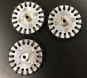
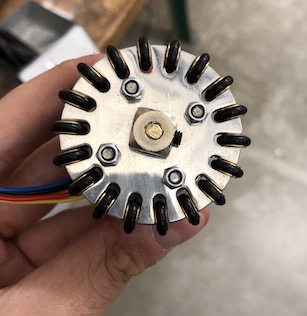
These are the Omni Directional Wheels I was able to borrow from the Harvard Undergraduate Robotics Club (the wheels are waaay too expensive to buy)
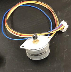
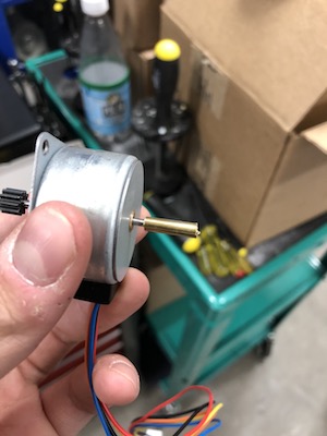
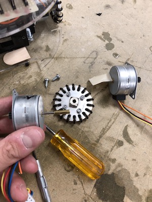
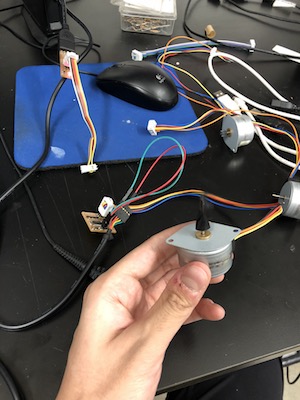
Lastly, this is the unipolar stepper motor I will be using for my jamBot (I will use 4 of these)
5 - The Robot’s Wheels
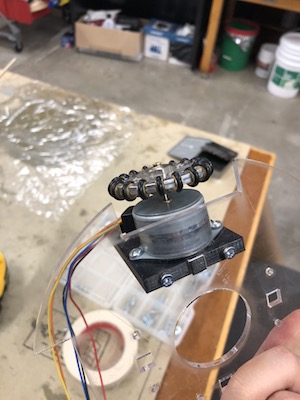
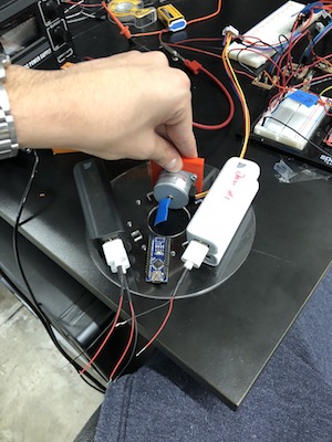
Ok, now that you have a general idea of what I’m building and how I plan to build it i’ll start by documenting how i center the wheels and the stepper motors together.
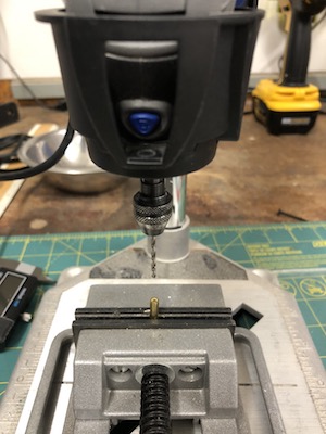
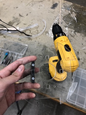
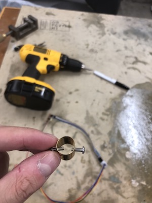
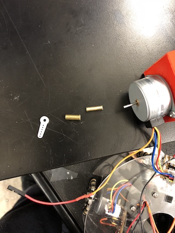
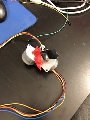
I used a 4mm brass rod and cut it into 4 small 13mm pieces as as shown.
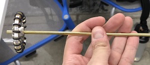
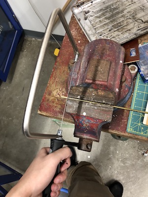
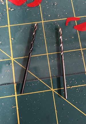
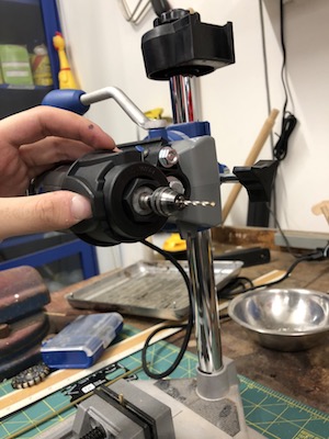
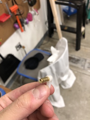
After that, I drilled a hole in the center of each of the 4 brass pieces (2mm wide). This while is where the motor’s rotational rod will be press-fitted. Drilling a hole in the center of a tiny rod is challenging, here’s how to do it.
Start the drill with a really slow speed and keep tapping the drill bit on the center of the rod… really slowly. The idea here is that this will create a small hole that can then hold your drill steady when you go on full speed.
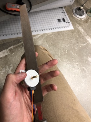
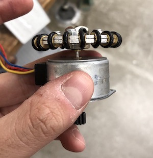
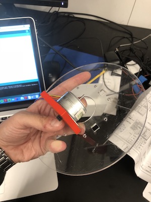
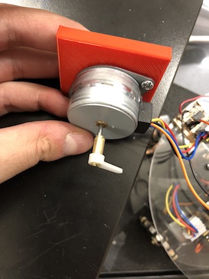
After I drilled the brass rod, I sanded it so it’s smooth on the edges and then hammered it to the motor… be strong but gentle here… careful not to hit your motor!!
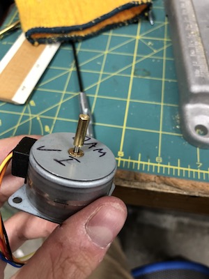
Finally, I hammered the wheels on and tightened the screw on the side of the wheel. Done!
6 - [2D + 3D] Fabricating the Robot’s Body
To create jamBot’s body, I used FreeCad to design several 2D and 3D components (I will discuss several other 3D components that I created in a later segment).
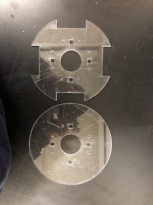
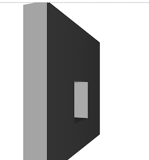
First, I designed a bottom and top shell for jamBot that would act as the main components holders. Below is my Freecad sketch followed by the laser cut clear acrylic final jamBot shell.

Left Image: bottom piece, the holes in the center are for the pen to pass through from and the 4 cuts on the sides are for the wheels to fit
Notes:
- Due to low supplies, I used old acrylic pieces… that’s why they look really scratched.
- I had to do the laser cuts around 4 times as the acrylic seemed to be too strong and didn’t fit any of the options listed in the GSD laser cutters. I talked to a TF there and we customized the power/speed to fit my need!
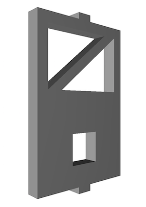
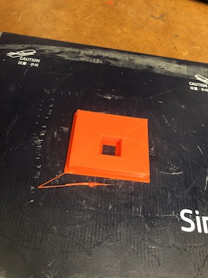
Now that I had my top and bottom shells, I designed and 3D printed 4 columns that would act as both ‘columns’ that hold the top and bottom shells in place and also as holders for my four stepper motors.
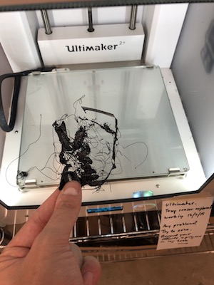
The Ultimaker kept failing to 3D print my columns as the PLA was not sticking to the bottom pad. To resolve this, I lowered the speed in the first 10 minutes of the print from 100% to 35% so that the PLA would have more time to stick. That resolved the issue!! after discussing this with several other people in the lab they recommended putting tape on the Ultimaker pad… that also worked well!!
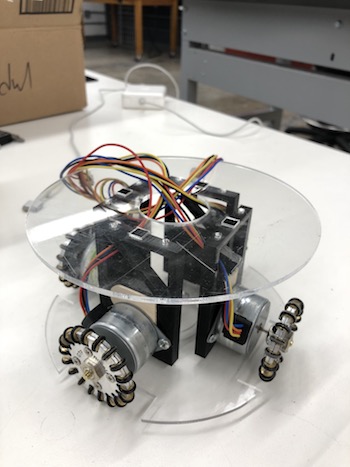
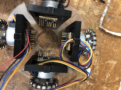
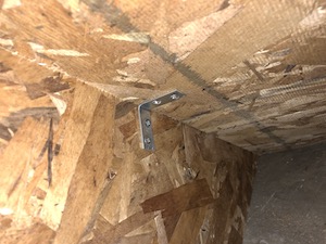
After 3D printing the columns, I screwed the wheels to the columns and the columns to the shells. I also noticed that the jamBot was not stable, so I added several wooden pieces to ensure that all wheels are touching the floor at all times.
7 - Electronic PCB
- 1 motherboard (Arduino Nano)
- 5 Slave boards for each of the stepper Motors
- 1 Slave board for the servo [ended up not using it]
- 2 bluetooth boards - check networks week for more info
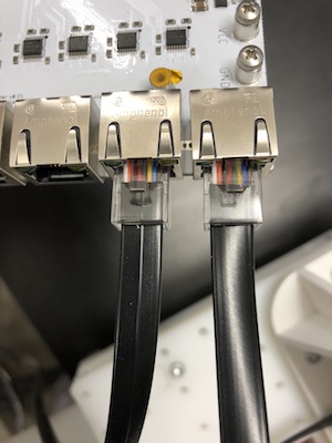
Note: motherboard and slave boards are connected with RX/TX cables. Motherboard receives information from the user and sends instructions to slave boards to move a number of steps in a certain direction.
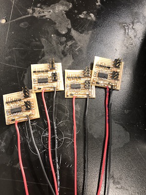
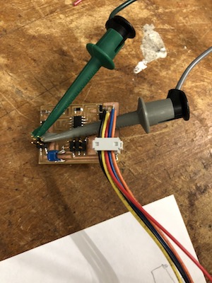
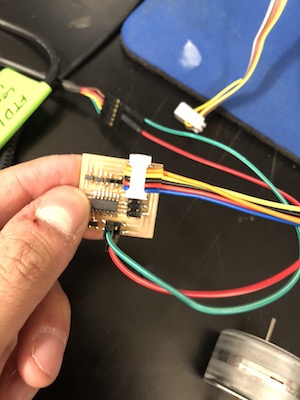
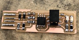
[1] Electronics PCB: Stepper Motors - jamBot Motion
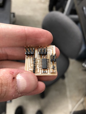
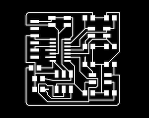
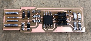
I redesigned Niels unipolar stepper motor board and added several capacitors to it to ensure a clear and steady transmission of information. I created 5 of these boards. Checkout my output week for more information on the boards and how to create them.
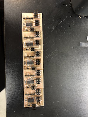
I wrote a dummy script in Arduino to test the boards and they all worked perfectly!!
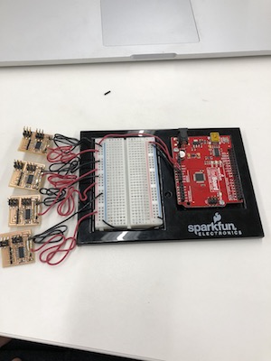
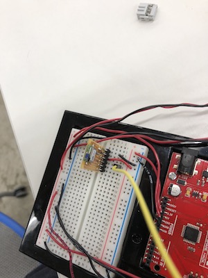
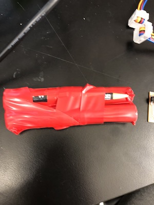
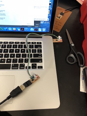
I removed the 2x2 header and added VCC/GND cables and rigged all the stepper boards to an Arduino board. The idea here is that the Arduino would act as the motherboard, which will be connected with RX/TX cables to the stepper boards and sends them instructions.
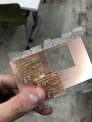
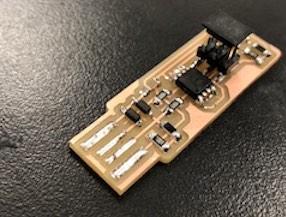
[2] Electronics PCB: Servo - Pen Motion
Now that I had the stepper motor boards setup, I designed a servo board that would hold the pen in the center of the robot and place it up/down to draw images with.
I wrote a simple Arduino script to test the board and it worked !!
[3] Electronics PCB: Communication - BlueTooth/Bus
Ok so now we have an Arduino that acts as a motherboard with 4 stepper boards and 1 servo board connected to it. I then connected each parallel pair of wheels together with an RX cable to the Arduino so that the information is relayed to both motors at the exact same time. This worked great for me as I wanted to draw pixelated images, meaning that the motors will always have to function in pairs.
I wrote a script to test my connections, looks solid!
After getting all that to work, I spent around 5 hours working on the RN4871 bluetooth module to get the mother board to receive wireless information rather than having it be connected to my laptop. I got it to work, but it was very unreliable as it keeps disconnecting for no reason. I decided to abandon this part of the project due to how unreliable the module was.
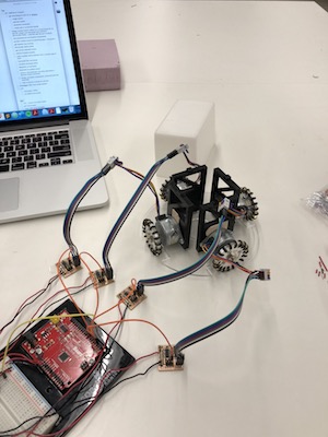
8 - Putting it Together
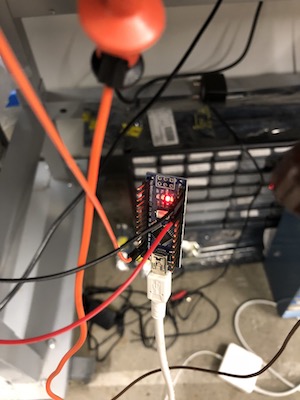
At this point I started realizing that i have way too many boards that are too big, the Arduino is just massive!
So, I decided to switch from using an Arduino Uno to using an Arduino Nano. The Nano worked just like the Uno but it’s just a lot smaller. I had to do some hacky things to connect the nano to my Mac but it wasn’t too bad. Checkout this link if you are coding a Nano with a MacBook CLICK HERE
While running some unit tests, I noticed that my stepper motors would sometimes run without me explicitly telling them to run… meaning that they are receiving an instruction from the motherboard RX cable telling them to run…. WEIRD!! Any how, I added a 22uF Cap to each of the boards and that helped, but it didn’t completely eradicate the issue.
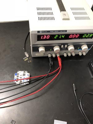
In addition to the random running issue, I soon realized that my robot is getting way too heavy for the stepper motors to move it with 7V power supply. After doing some research, I decided to rig a 15V power supply to the motors and a 5V power supply to the boards. This solution not only gave my motors more torque, but also eradicated the noise in the wires that was randomly telling my stepper motors to move. Happy happy happy!!!
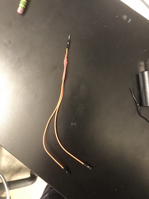
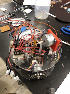
Below are some other wires and boards I built to put things together.
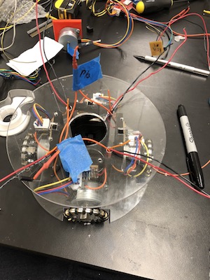
IT MOVES!!!
9 - Pen Movement Mechanism
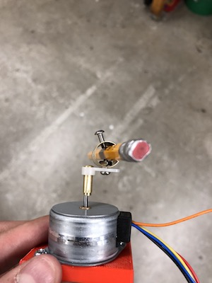
To rig the pen and move it, I first tried working with a servo but I soon realized that using a stepper motor would be more precise. Therefore, I took off the servo and board I built for it and replaced it with a 5th stepper motor that hangs from the top of the jamBot.
I designed this 3D printed rig that holds the motor firmly to the board.
Then I made this hacky pen holder device that you can screw a pen with in the middle.
This is how I imagined it looking.
Ok now back to the pen rig! So attaching the pen was pretty complicated. I had to attach the motor to a 4mm metal rod with a 2mm hole in the center that I drilled. Then attach the rod to a bigger empty rod from the inside. Then attach the last rod to the white plastic piece that would be screwed to the pen holder. It looks very hacky, but hey, it works!
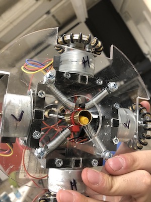
If the pen is only held from the top would essentially just dragged from the bottom so it keeps bumping on the sides and moving like crazy… I had to put a stop to that. So, I made this spring system that looks doope and actually works really well. It does one job only, and it does it really well. It centers the pen on the x-y axis while the stepper motor from the top lowers/lifts the pen.
10 - Programming
All my code can be found in the files section at the end of this page.
Here’s what I did:
- User sends information to Arduino Nano - Motherboard
- motherboard parses information and builds packet to send through a TX cable to the slave boards
- the slave boards receive that information and parse it… then do an action
An interesting issue that I was working on was how to ensure that the pen stepper motor moves the pen down and holds it still in that position. Now this might seem simple, but the issue is that the pen is using Niels get_char function to read serial input which uses a polling algorithm to fetch serial information. The issue with polling algorithms is that they stop all other functions from running until the poll is accepted and then the program proceeds. This means that while the algorithm is polling, the motor stops working and the pen can easily move up.
I wrote a script that resolves the polling issue by making the motherboard end the polling algorithm in the slave board quickly by essentially sending it specific information telling the pen stepper motor to stay stiff. By doing that, the stepper motor’s get_char ends the polling as it receives a message and the motor stays charged and stiff all the time.
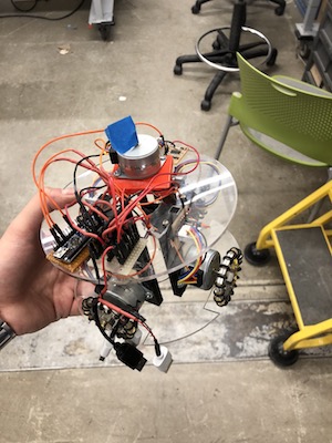
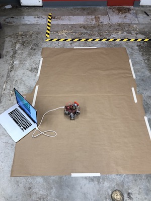
11 - The Final Product
That’s my testing area!
I overheated one of the engines last minutes so I had to replace it
These are the things that I built for this project but never used:
- really cool servo board
- Touchpad
- Bluetooth - it was waaay too unreliable for me to use it
Here’s my final prodcut!!!!!!!!
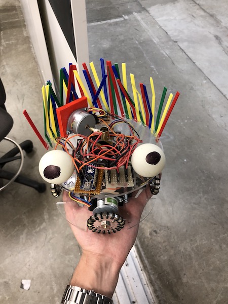
That’s me doing some initial testing
AND THAT’S jamBot drawing a square - sort of a square
12 - Files (Click to open links)
#14 Wildcard Week
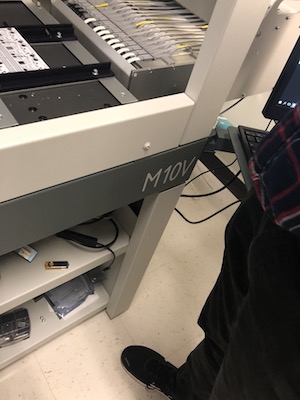
Pick & Place Machine with Jake!!
For my wild card week, I joined the Pick & Place session with Jake. In this page, I will document what we did in the session as well as showcase what I did for the assignment.
Session Summary: We went over how a Pick & Place Machine works, the steps needed post/prior to using the machine, manufacturing boards, and many more cool topics!
Assignment: Go through the process of exporting a board to a ‘Board House’ for Fabrication
Process Outline:
- Eagle Export for ‘Board House’ Fabrication
- Solder Paste-ing
- Pick and place-ing
- Reflow-ing
[Assignment] Phase 1: Eagle Export for ‘Board House’ Fabrication
The first step of the process is to design a board and make it ready for manufacturing. This essentially means that you’ll take your design from ‘EAGLE’ or any similar platform, add all the manufacturing details to it, and send it to a manufacturing house to be printed for you.
In addition to having your regular EAGLE design that we know by heart now, you need to keep track for several other layers to ensure that the ‘Board House’ can manufacture your board. These layers are the following:
- Top - Top Copper
- Bottom - Bottom Copper
- Dimension - The Cutout Layer
- tStop / bStop - Top and Bottom Solder Masks (as in, stop the solder mask on these areas)
- tCream / bCream - Top and Bottom Solder Stencil Openings
- tPlace / bPlace - Silkscreens (text / drawings)
Once you have your design along with these layers, you can go ahead and generate INDUSTRY STANDARD files that structure this information in a way that all ‘Board Houses’ will understand, the file format is called “GERBER” files. To generate these files, you can simply click on the manufacturing icon on the top left corner of eagle or you can do it the SparkFun way through this tutorial linked HERE.
After you generate these files, you can go ahead and pick a board house to manufacture your board at.
Here are a few Board Houses that Jake pointed out:
When you place an order, you will be asked to upload the gerber files you generated along with some aditional information such as the amount of copper you’ll be using, the size of the board, and several more things.
I used JLCPCP and here’s what there process looks like:
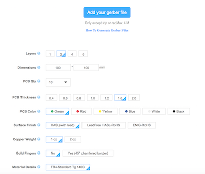
The manufacturer will review your order, confirm it, charge you, and send you the boards you ordered in 2-3 days.
Here’s what you’ll be receiving. Essentially the equivalent of a milled board.
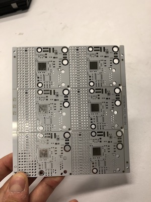
For my assignment, I created gerber files for a servo board that I’ll be using for my final project. I essentially designed the board, added the needed layers, created the gerber files, went through sending my files to JLCPCB and then ended up not order the boards because I don’t actually need many boards so I’d rather just mill them myself and incrementally test them.
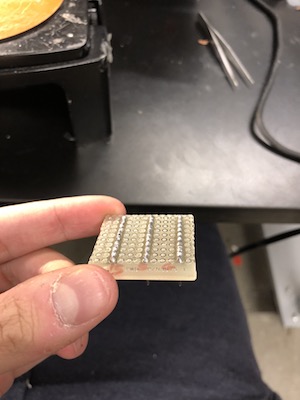
Phase 2: Solder Paste-ing
Now that you have this board with all the holes and outline/traces that you need, you can start assembling the components!
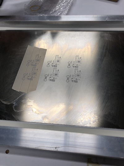
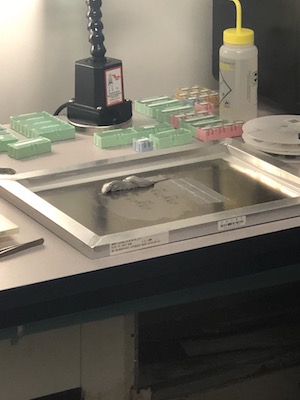
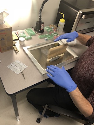
To start, you need to spread solder paste on the whole board. You can use something like this metal laser cut sheet to quickly place solder paste in the correct places.
Note: Solder paste can quickly dry up, you can add reflow to it and you’ll be set!
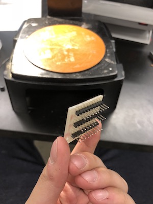
Phase 3: Pick and place-ing
Now we get to use the pick and place machine!!
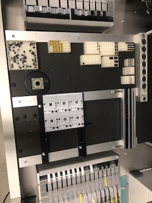
Essentially the machine takes boards with solder paste on them and place the components on the board. Keep in mind that this machine is simply just placing the components, it’s not actually soldering the components or anything.
Each component must be registered in the machine, the machine uses computer vision to register your components and their places… pretty cool.
Additionally, there are two ways to feed in components to the machine, you can have rails of comonents, which are used for frequently used components, and there are trays of components that the machine can detect and register… these are used for less frequently used components.
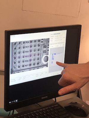
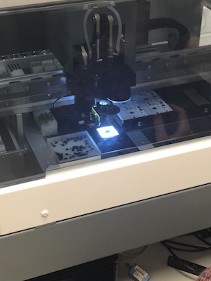
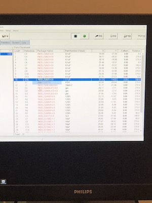
Once the machine gets started it goes really fast, but getting it started is a bit of a hassle because you individually have to register each component and it’s position… that can take 10 mins or so.
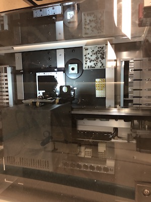
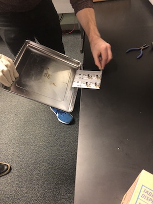
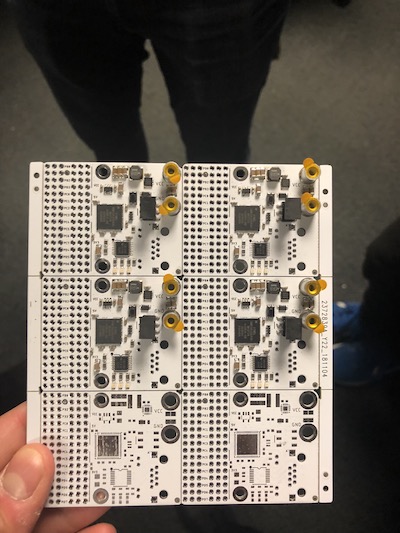
Phase 4: Reflow-ing
Take the board with the components on it, put it in a reflow oven, and boom… you got a ready board!!
#13 Networking and Communications
Connected Bluetooth Network
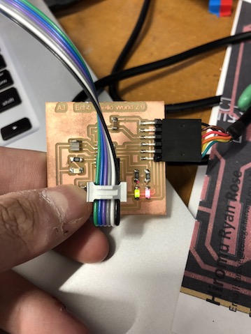
For this week’s project, I built two RN4871 (2.4 GHz Bluetooth) boards that I plan to use for my final project to communicate between a robot and a touchpad.
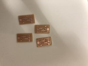
Step 1: Fabricating the Boards and Milling them
I used Niel’s board to fabricate and mill my board.
Files:
- [Board Traces] (https://drive.google.com/file/d/1XoS86zQDp9XvEH_8krq-5OelJ3hG8qGw/view?usp=sharing)
- [Board Borders] (https://drive.google.com/file/d/1oyDGoekN3iplIaoZZQWIV94j2VjMXWPO/view?usp=sharing)
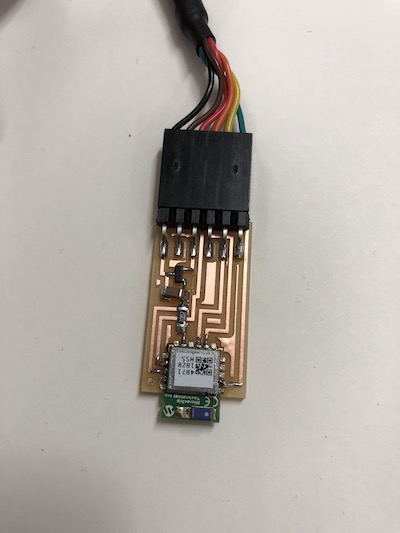
Step 2: Attaching Board Components
List of components:
- RN4871 (2.4 GHz Bluetooth)
- 10K Ohm Resistor
- 1uF Capacitor
- 3.3v IC Divider (out, in, ground)
- 1x6 header (you actually only use 5 of them, RTS is never used)

Step 3: (Phone to RN4871) Enabling Communication
To test your board, simply connect it to your computer with an FTDI cable and follow the following instructions:
- Download CoolTerm on your laptop from [HERE] (http://freeware.the-meiers.org/)
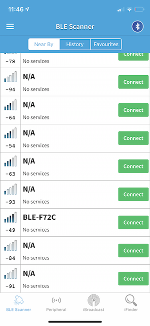
- Download the ‘BLE Scanner’ app on your Phone
- Connect the RN4871 board to your laptop with an FTDI cable
- Open CoolTerm Options->Serial Port and pick the port your Bluetooth board is connected to then set the Baudrate to 115200. press ok
- In CoolTerm, press connect then type in the follow (1) $ the command line should automatically appear. If it doesn’t then your board has a bug… maybe add some capacitors? that’s what I did and it helped regulate the connection
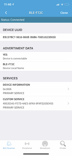
- Open the BLE app and find the connection, it will be called BLE-F72C. Connect to it
- In BLE, click on CUSTOM SERVICE, choose to write a message, they type anything while making sure you are typing a text not hex. Press enter and you should see your message go from your phone to the CoolTerm terminal on your laptop. SIIIICK!
Step 4: (RN4871 to RN4871) Enabling Communication
Note: Refer to my final project for an update on this step
Link to final project: CLICK ME
#12 Interface and Application Programming
UI for my Touchpad from Input Devices Week
For this week’s project, I will create a user interface that mimics a user’s drawing on the input touchpad I created in the ‘Input Devices’ week.
The idea here is to make a python GUI that acts as a drawing pad. However, this won’t be the regular drawing pad that takes input from the users mouse, rather it’s input would be from the touchpad I created in the ‘Input Devices’ week.
IMPORTANT NOTE: This week’s assignment is heavily dependent on my final project as I will be using a more advanced and developed version of this interface to relay information from the touchpad to a robot that I will be building. Please refer to my final project for grading this week’s assignment. Click HERE to go to my final project.
The video above shows the python GUI I built with tkinter that essentially takes touchpad input and draws and image with it on the screen. Additionally, I created two buttons on the screen, a reset button and a send button. The RESET button will delete the current drawing on the screen, while the SEND button will send instructions via bluetooth to a robot that can mimic the same drawing (refer to my final project for more information on this).
Below is the code that creates a drawing canvas that takes touchpad input to draw an image.
###Drawing Code:
from tkinter import *

canvas_width = 500
canvas_height = 500

def sendToRobot():
    print("Sending drawing instruction to jamBot through bluetooth")

def reset():
    print("Image is deleted")

def paint( event ):
   python_green = "#476042"
   x1, y1 = ( event.x - 1 ), ( event.y - 1 )
   x2, y2 = ( event.x + 1 ), ( event.y + 1 )
   w.create_oval( x1, y1, x2, y2, fill = python_green )

master = Tk()
master.title( "Abdul's Touchpad Painter" )
w = Canvas(master,
           width=canvas_width,
           height=canvas_height)
w.pack(expand = YES, fill = BOTH)
w.bind( "<B1-Motion>", paint )

message = Label( master, text = "*Draw Pixelated Imaged" )
message.pack( side = BOTTOM )
button_reset = Button(text="reset", command=reset)
button_reset.pack()
button_send = Button(text="send to jamBot", command=sendToRobot)
button_send.pack()

mainloop()
TouchPad Input Code:
This is the code that reads input from the touchpad I created in the input devices week and sends the finger location to the drawing code to be processed. This last step is currently in progress as I am rebuilding my touchpad and thinking about better ways to relay information from the touchpad to the digital drawing.(Refer to final project for more details)
from Tkinter import *

from serial import Serial

def idle():

   ser.flush()

   input_x = ser.readline() # 4,5,6,7
   input_y = ser.readline() # 0,1,2,3

   x = int(input_x[0])
   x_status = int(input_x[1])

   y = int(input_y[0])
   y_status = int(input_y[1])

   print 'x: ',x
   print 'x_status: ',x_status
   print 'y: ',y
   print 'y_status: ',y_status

   print '------'

   if x_status == 1 and y_status == 1:
      min_val = min(x,y)
      max_val = max(x,y)

      if 4 <= max_val <= 7 and 0 <= min_val <= 3:
         max_val = max_val%4
         print "(x,y) = "+"("+str(max_val)+","+str(min_val)+")"


if (len(sys.argv) != 2):
   print "serial port arg"
   sys.exit()
port = sys.argv[1]

ser = Serial(port='/dev/cu.usbserial-FT9PFE5G', dsrdtr=True)

while True:
   idle()
Issue:
The issue that I’m facing is that my physically fabricated touchpad is not fully functional, meaning that it’s shorted somewhere and I have to rebuild it. Therefore, I’m unable to test whether the system I setup above is fully functional or not.
At this point, my drawing GUI is taking input from the laptops’ mouse and I set it up in a way that makes it really easy to give the GUI any numerical matrix input and it “graphs” it. In my final project, I will rebuild my touch pad, connect all the programs above together, and finally have a beautiful fully functional system!
Files:
- Touchpad Drawing Code++ is (check the touchpad_draw.py file) HERE
#11 Machine Design
Camera Rig
In this week, I worked with the Harvard section team on building an automated camera rig machine that moves linearly and rotationally to shoot panoramic pictures. More specifically, I focused on the coding part of building the machine.
Step 1: Debugging the Boards
After the Electrical team handed us two 23 Stepper motors with boards to code, the rest of the coding team uploaded the appropriate firmware into the boards and handed them to me and Jeff. Our plan was to first connect one motor and get it working then then hookup everything else and create a planned motion.
With this plan in mind, we spent around 3 days debugging the first stepper motor as we were able to connect to it but not move it. After a long time of looking into Jake’s code and not finding the bug, we reached out to Jake. Jake and Jeff (from my team) met and worked on fixing this movement issue together.
They found out that the board we were working with was malfunctioning, so simply switching the board fixed everything.
Step 2: Hooking Up the System
Now that we fixed the initial motion bug, I hooked up the whole system together as shown below.
Connecting both motors
Supplying both motors with power
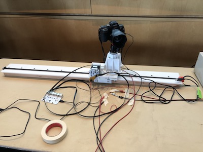
Complete rig
We had to rewire all the boards on the engines the last minute so I took care of that and then coded the rig’s planned motion.
Step 3: Moving the Motors
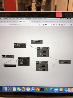
After connecting everything together and testing the motors movement, I went ahead and made a simple program with Jake’s RNDMC interface that moves the rig linearly and rotates the camera accordingly as shown below.
Step 4: Presentation
I was also in-charge of presenting everything related to coding, from uploading the firmware to creating the planned motion. Additionally, I put on a brief demo for the class!
#10 Output Devices
Drawing Car
Introduction
In this week, we were tasked to add an output device to a circuit and program it to do something. I decided to make this week help me prepare for my final project, so I worked on building two circuits, where each one controls a stepper motor. The idea here is that I’ll be using these stepper motors to make a small remote controlled car that I will be using for my final project.
IMPORTANT NOTE: My final project will heavily extend this project. Please refer to my final project for end results for this week.
Initial Testing
After discussing this idea with Rob, he gave me a unipolar stepper board that he had made a while ago. I took this board, attached a 5V power supply to it, grounded it, and plugged a stepper motor into it for testing. Unfortunately, the board seemed to not work.
Although the board didn’t work, I looked closely on how it was built and used that as a stepping stone for my design. Additionally, I used Niel’s Unipolar stepper design to create my board.
Milling and Fabricating the Board
Milling the board and attaching the components was pretty simple.
Components:
- Tiny44
- 10K resistor
- 1uF Capacitor
- x2 2x3 Header
- 2x2 Header
- 5v Regulator
- x4 Mosfets
Programming and Testing
I used Niel’s script for the Unipolar stepper motor as a basis for my code and I wrote a simple script on top of it that makes the motor rotate 180 degrees clock-wise and then reverse its action.
Buuurn?!?!?
This whole time, my board was getting power from my laptop. I decided to plug my board to a set of batteries, so I connected several 1.5V batteries together to make a 6V battery. I then attached this set of batteries to my board, and after a couple of minutes it fried my board (SAD :( )
Files:
#09 Input Devices
Touchpad
Introduction
In this week, I decided to build a touchpad that enables users to draw on it with their finger and see their visualization on a simple web application. I used Matt Blackshaw’s Touchpad for reference throughout my implementation. Matt’s design is based on Niel’s step response project.
###IMPORTANT NOTE: This project will be expanded on in my final project. I plan to add a bluetooth component to it and make it communicate with a robot that I’ll build.
STEP 1: Designing the Board
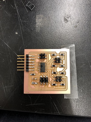
Looking at Matt’s design, I took his files and iterated on them to create a better routing pattern by decreasing the number of Air-wires. Below is the board design I settled on.
STEP 2: Milling the Board and Adding the Components
List of Components:
- x1 ATiny44
- x8 1M Ohm Resistors
- X1 0 Ohm Resistor
- x1 10K Ohm Resistor
- x1 1uF Capacitor
- x3 2x2 Headers
- x1 1x6 Header
- x1 2x3 Header
Milling the board and attaching the components was pretty simple. The main challenge in the board creation process was connecting the 2 air-wires I have. I didn’t want to have wires going on top of the board, so I drilled the board and made the connections with copper vinyl sticker on the bottom side of the board. I tested the connections and they all work properly!
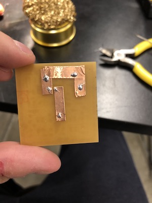
- Drill the board -> I should have made the milling machine do this
- Add the copper tape on the back side -> I wanted to use a double sided board to do this but couldn’t find one at the time
- Make holes in the copper tape -> do this after you drill, otherwise the tape would come off
- Place a wire through the holes and make the solder stick to it… it flows really smoothly if you do it right
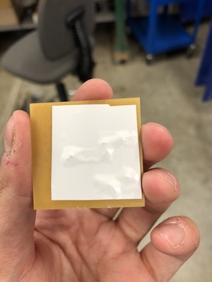
- coper the bottom side of the board with insulator (vinyl to protecting from shorting with its surroundings)
- I know that this is not an ideal solution but I thought it’s pretty hacky and cool… and it works!
STEP 3: Building the Touchpad
I used Matt’s Touchpad design to cut a piece of copper and stick it to a wooden square. I also made some wire connections with 2x2 headers that attache to the Touchpad, as shown below. This design has 31 touch points, which should be enough for this week’s assignment.
Now after taking matts touchpad design (attached below in the files section), I vinyl cut it with copper. I first peeled the copper of and placed it on a piece of vinyl to increase its adherence so the cutter doesn’t misplace it.
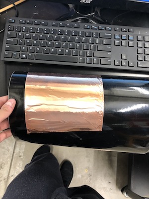
As hsown below, the cut looks great. It’s time peel it!
Peeling this was really hard, I had to redo the cut 3 times to get it right. Finally, what I did is that I peeled around the columns and kept the nodes in the column connected together while separating the row nodes. I then cover the column and row intersections with vinyl as shown below.
Then, I took a 4 strips of copper and placed them to connect the row nodes together. The copper vinyl is not conductive from the bottom, so I had to add some solder on the top of it so it connects the rows together.
Finally, I attached wires to each column and row to get it’s input value.
STEP 4: Programming the Board and Testing it
I wrote a simple python script that takes the input of my touchpad and outputs the x,y coordinate on the screen. Below is a video that shows my current functional touchpad (IMPORTANT NOTE: I WILL WORK ON VISUALIZING AND EXTENDING THIS OUTPUT FOR MY FINAL PROJECT, PLEASE REFER TO MY FINAL PROJECTS FOR UPDATS/MORE DETAILS):
[UPDATE] Issue
After extensively testing my touchpad, I found that some of the rows/columns are not properly connected together. This results in my python script to sometimes not register the correct inputs (you can see this if you look closely in the video attached above).
I will create a new touchpad design that has less column/row overlappings for my final project.
Files
#08 Molding and Casting
Casting a LightBulb
Introduction
In this week, my task was to design a 3D mold around the stock and tooling, mill it, and use it to cast a part.
Step 1: Creating a Design
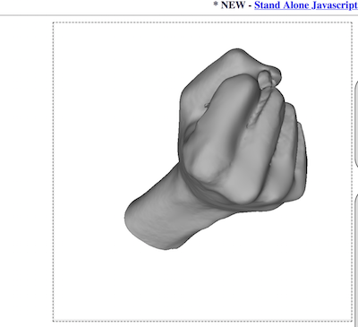
I decided to cast a fist bump, so I used the sense 3D scanner to scan my hand making a fist bump as shown below.
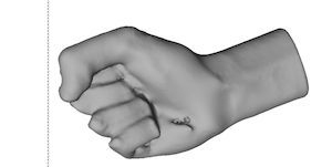
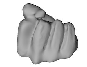
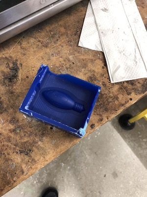
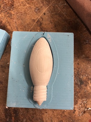
After think about how to cast it, I realized that I would have to have multiple molds to be able to create the shape I wanted to make and a fist pump specifically would be too complex. Therefore, I opted for scanning a light bulb and molding it as that would only require two symmetric molds. I painted a lightbulb black with a sharpy and scanned it with the Sense 3D scanner.
Step 1: Creating the Positive Mold
First, I cut my scanned lightbulb into two halfs and deleted one as both halfs are symmetric. Below is the shopBot running my cuts!!
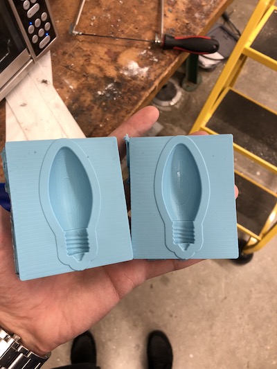
Step 2: Creating the Negative Mold
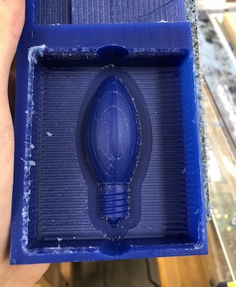
Following the milling, I used OOMOO 25 (10:13 A:B ratio) to cast my negative version of the mold. I did this twice so that I create a solid container for my lightbulb shape than I can pour whatever material I want in.
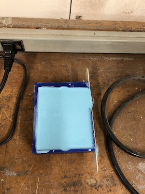
As you can see above, I broke one side of my positive mold because I cut too close to the side. I fixed this by glueing a wooden plate on the side to hold the OOMOO.
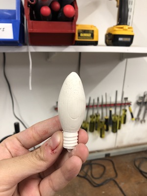
Step 3: Getting my Final Cast
I mixed 100g Drystone powder: 32g H20 to make my casting material (that’s the ratio, I made much more than that). I then filled my mold and waited for almost 2 hour for it to dry.
After pouring in the drystone mix, I gently tapped the cast to get all the bubble out, I think this helped a lot as my mold wasn’t TOOO bubbly. However, next time, I will add a breathing whole for the bubbles to go out from. That is, I will have two holes in my cast, one for pouring in the drystone mix and one for the air to come out from.
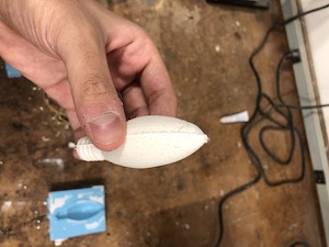
As you can see above, my cast had some bubbles in it :(. Make sure to get all the bubbles out as much as possible. You can do this by slowly mixing the materials together (DON’T GO CRAZY ON STIRRING!!) and pour it in really slowly + the notes I added above.
Step 4: Refining my Cast
I sanded the sides of my cast to refine it.
#07 Embedded Programming
Binary Counter
Introduction
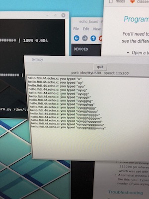
In this week, we were asked to program the echo boards we previously built and read a microcontroller data sheet.
Reading a Data sheet
Given that my Echo board, found HERE, uses a ATTINY44 I read the the most important parts of the TINNY44 data sheet found HERE
Reprogramming my Echo Board
Reprogramming my echo-board with the initial echo C-file I had was pretty simple as it didn’t including adding any libraries or interacting with any new technology. Therefore, after playing around with that environment for a bit and testing simple programs such as turning my 3LEDS on and off when the button is clicked, I decided to shift from using the C-files to using the Arduino platform.
I used the Arduino platform to program a 3 bit binary counter that increments in value as you click a button as shown below.
Here’s how it works:
Given that I have 3 LEDs, I can count from 1 to 7 in binary. In the image above, you can see 2 LEDs on and the third one on the left side of the board is off indicating thet we are at the 3rd button click.
Given that I was using the ATTINY44, I used the image below to figure-out how to route the pins accordingly.
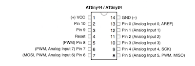
Additionally I followed THIS tutorial to learn how to connect Arduino to my ATTINY44.
http://highlowtech.org/?p=1695
This is the code I wrote to operate my 3 bit binary counter.
const int led_pin_0 = 8;
const int led_pin_1 = 3;
const int led_pin_2 = 2;
const int button_pin = 7;

int buttonState = 0;
int count = 0;

void setup() { pinMode(button_pin,INPUT); pinMode(led_pin_0,OUTPUT); pinMode(led_pin_1,OUTPUT); pinMode(led_pin_2,OUTPUT);  }

void loop() { digitalWrite(led_pin_0, LOW); digitalWrite(led_pin_1, LOW); digitalWrite(led_pin_2, LOW);

buttonState = digitalRead(button_pin);

if(buttonState == LOW) {

} else {
  count++;

if((count % 2) > 0) { digitalWrite(led_pin_2, HIGH); } else { digitalWrite(led_pin_2, LOW); }

if((count % 4) > 1) { digitalWrite(led_pin_1, HIGH); } else { digitalWrite(led_pin_1, LOW); }

if((count % 8) > 3) { digitalWrite(led_pin_0, HIGH); } else { digitalWrite(led_pin_0, LOW); }

delay(200); } }
##IMPORTANT NOTE: This week’s assignment will be further utilized and expanded in my final project. Please refer to my final project’s ‘PROGRAMMING’ section to see my extended work for this week. You can find my final project’s page from HERE
#06 Computer Controlled Machining
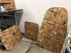
Sliced Plywood Table
Introduction
For this week’s assignment we were simply asked to make something BIG. I always wanted to buy a new coffee table for my common room but I never really got one. So, I decided to build one this week!
Step 1: Designing the Table
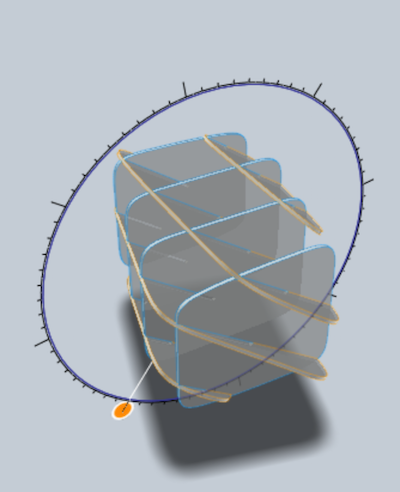
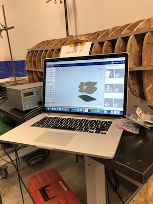
I used Fusion360 to design my table. In fusion, I simply just placed a rectangular block in the center of the screen with the dimensions I wanted (43in x 25in x 25in) and exported it to slicer. Slicer (LINK) is a really cool plug-in for Fusion360 that takes any 3D shape you give it and simply slices it to represent it as interlocked pieces of the material you give it.
This is the Fusion 360 block I created.
After exporting the block to slicer, I auto-generated the slices and got a really dull/boring shape. So I started editing the shape to make it look nicer yet maintain it’s strength and ensure that it could be used as a table. Below is the slicer design I finally decided to go with.
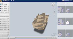
My idea was to create a cool table by having a plywood frame that holds a glass sheet on top of it. As you can see in the design, I made sure that I can place a glass sheet on top of the plywood frame by making it even on the top and bottom.
Step 2: Setting the Toolpath (MM vs Inches!!!!)
I used the ShopBot VCarvePro platform to create the tool-paths for my cuts. I initially started by decreasing the usage of 4x4 plywood sheets by fitting as many parts as possible in one sheet (I ended up using 3 4x4 plywood sheets).
Following that, I set the drill path and the profile path for each of the cuts. Initially I confused the units of the cut depth and set the cut depth to 12 inches rather than 12 mm, which resulted in me almost causing a fire with the cutter. Fortunately, Rob and I were able to shut-down the machine and figure-out the issue before anything serious occurred.
With my edited tool paths, I went ahead and started cutting!
Step 3: Cutting the Pieces
I screwed down the plywood onto the shopBot sacrificial layer and I added several nudges to my design so that the center pieces stay intact throughout the cut.
Step 4: Assembling the Table
Slicer has a an interesting user interface that shows you how to assemble your sliced structure after cutting the pieces. Unfortunately, this interface is not great because it doesn’t ensure to give you the easiest way of assembly, rather it just gives you a possible way of assembly. While taking slicer’s approach I almost broke my plywood pieces because they are two heavy and slicer was asking me to place some heavy pieced on top of a smaller piece which at that point of assembly, wouldn’t have had much support. I decided to assemble the table without using Slicer’s guide. -> I used their guide to see where things fit thought… which makes assembly so much easier!
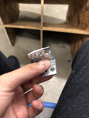
I soon realized that one of my cuts had an outer tool-path cut rather than an inner tool-path cut. This means that my slots for some pieces were way too big to ensure a stable tight fit.
I went to a nearby hardware store and bought some metal corner connectors and screwed them to the larger slot pieces to ensure a good stable fit.
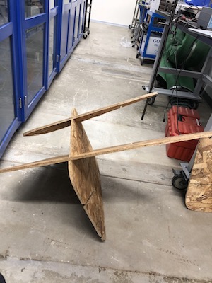
With that, I had a beautiful coffee table!
Files
- All the DXF files are created can be found HERE
#05 Electronics Design
Designing and printing boards
Introduction
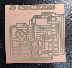
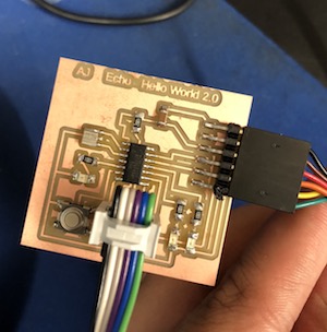
In this week, I redesigned the echo hello-world PCB and added a button and 3 LEDs to it. I felt that this was the hardest assignment up till now as it forced me to go through several tutorials, learn more about how to program PCB’s, and debug boards.
Step 1: Eagle Tutorials and Fab Libraries
To start off, I chose Eagle as a tool to draw my recreation of the echo hello-world PCB. Eagle has great support from the Fab class, which means that TFs will be able to help you if you are lost and it also has greate simple tutorials. I started by following these three basic tutorials: (1)How to Install and Setup EAGLE - LINK,(2) Using EAGLE: Schematic - LINK, (3)Using EAGLE: Board Layout - LINK.
After getting accustomed to EAGLE, I went ahead and downloaded the fab components library and the fab design guidelines from HERE. You can learn more about how to use a library from the “How to Install and Setup EAGLE” tutorial, linked in the previous paragraph. To test the design rules in Eagle, type DRC in the top search box in EAGLE, press load, navigate to the fabcity design rules (found inside the fab library you downloaded from gitlab), and then press check.
This check will output a list of errors that you might have, fix them and you’ll be set for milling!!
Failed Board - #1
After going over some EAGLE tutorials, I went ahead and started redrawing the echo hello-world board. After doing some initial tests on the EAGLE platform, my design seemed to work, so I went ahead and milled it. Unfortunately, after milling the board, I realized that some wires were too close to each other so they merged, the routes were too thin, and the capacitor position was too small. Shown below.
Take Aways:
- Check that you inputted the correct Components in Eagle as not all components of the same genre are the same size - I added a smaller capacitor than the board needs
- Run the fabcity design rules
NOTE: I didn’t realize that I can check my board with the fabcity design rule as described above at the time of making this board
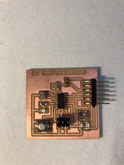
Failed Board - #2
I went back to EAGLE and fixed all those initial problems. After milling it, I realized that I forgot one route, so I just added a thin wire under the Tiny44 that creates that connection. After adding the components and attempting to program it, I found out thst the wire connection I added was not stable… it would sometimes short the board
Take Aways:
- Run the fabcity design rules - it detects all air wires
To be clear, adding the missing wiring under the TINY44 is merely for aesthetic reasons… I just didn’t want to have an extra wire above the TINY44. Adding this wire under the TINY44 was very tricky because it had to be really thin to fit, which made it very difficult to adjust and stabilize. I suggest you don’t add extra wires under components as it really hard to fit them and debug them later on. If you had a similar problem to me, either re-mill the board or create a wire that goes above all components or maybe drill the board and wire it on the back side.
NOTE: I didn’t realize that I can check my board with the fabcity design rule as described above at the time of making this board
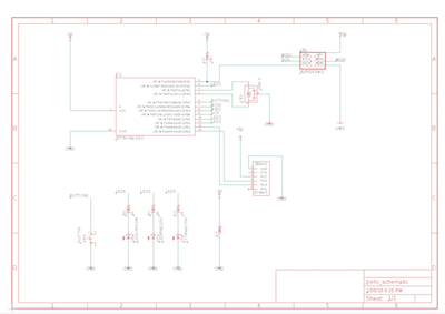
Redesigning the Board
At this point I finally realized that I can test my board with the fabcity design guide, so I did that, fixed all my mistakes and everything worked!
Below is my board schematic and final design.


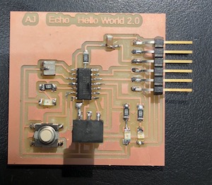
Step 5: Attaching Components and Programming
Lastly, I attached the components and followed the programming instructions for the echo hello-world found.
List of all the components I used:
- x1 Button
- x1 Reonator, 20 MHz
- x3 LEDs
- x1 Attiny 44- ssu
- x1 2x3 header
- x1 6 attacher
- x1 10k resistor
- x3 1k resistor
- x1 capacitor 1uF .
It’s important to note the the echo hello-world program won’t make any of the LEDs worked as it doesn’t communicate to them. Therefore, I made a simple program using the Arduino IDE that makes the appropriate tiny44 LED pins pass electricity that makes all the LEDs blink once the button is clicked. Check THIS tutorial on how to program a TINY44 with arduino.
Files
NOTE: DOUBLE THE DPI IN THE MODEL WHEN YOU MILL THIS. This is a Mac Retina display specific issue
#04 3D Scanning and Printing
Additive Designs and 3D Scanning/Printing
Introduction
In this week, our assignment was scan an object with a 3D scanner and design an additive model and 3D print it. Let’s get started!
Step 1: 3D Scanning
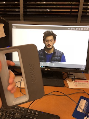
I used the 3D Systems Sense scanner, which is a really easy to use state of the art portable scanner. As for the object to scan, what’s better than scanning myself!
Using this scanner is straightforward. You choose the type of object you are scanning on the scanning platform, press start, scan the object from all directions, and finally hit save. With that, the Sense platform will create a 3D model of your scan and give you the option to edit and fill the model as you see fit. Checkout the results of my scans.
If you look closely in the video, I just scanned myself from the front and sides and then filled the back with Sense’s auto filler. It’s a great platform! -> checkout some helpful tutorials for using the Sense platform/scanner HERE
Step 2: 3D Additive Design
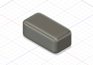
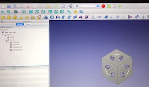
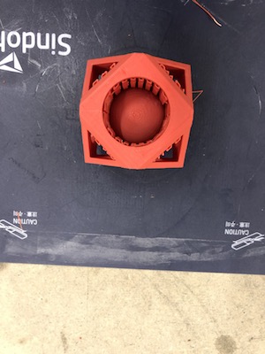
I wanted to design something that looks novel, yet be sturdy at the same time. Additionally, I wanted to make it clear that my design was additive. Therefore, I decided to design a cool box, with a sphere inside of it. I used FreeCad for this design.
I started with two 3D box parts. I placed both boxes inside of each other (one is 10 mm smaller than the other) and then I added three cylinders from each side with a length longer than the side of the larger box. I then boolean cut the cylinders and the small box from the larger box to get the shape shown below.
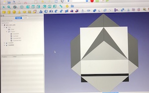
Following that, I wanted to add some cool edge cuts on the corners. So I placed my original shape inside of two larger boxes that are 45 degrees of off each other. Then I boolean cut the two encompassing boxes from my initial shape.
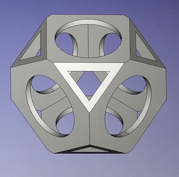
With that, I was done with the ‘BOX’ structure. Finally, I added a sphere in the middle of my box and ensured that the sphere won’t be able to slip out of any holes in the box by making the sphere’s diameter larger than that of any of the holes in the box.
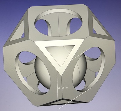
Isn’t that so cool!
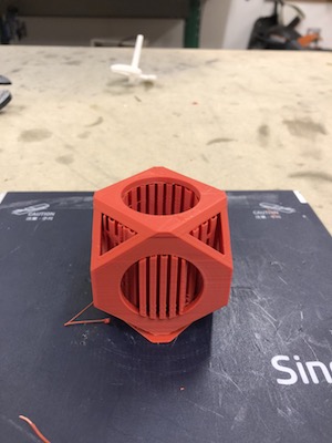
Step 3: 3D Printing
Now that I had my design, I printed it with a Syndoh printer.
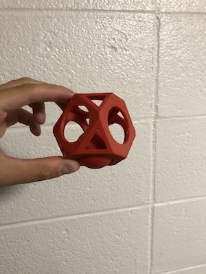
The red wiggly parts on the side are supports, I had to remove them.
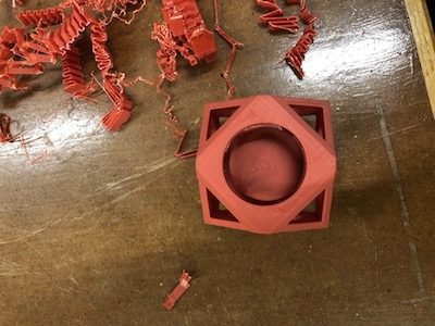
I finally have my structure!
Files
#03 Electronics Production
Creating and In-Circuit Programmer - PCB
Introduction
In this week, our assignment was to build the famous FabTinyStar, which is an in-circuit programmer that many Fab student have developed and worked on in the past several years. For my specific implementation, I followed Brian’s detailed instructions on how to build the FabTinyStar which can be found HERE. In this report, I’ll give you an overview of how I went along with the implementation. Lets get started!
Step 1: Mill a PCB
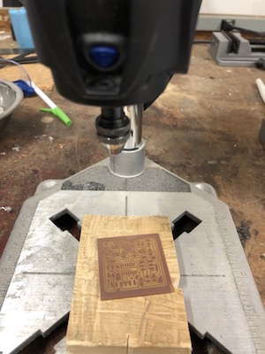
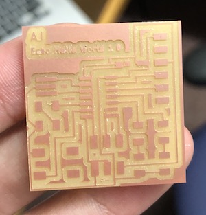
To create the PCB, I milled a copper sheet of thickness 35um. I ‘printed’ the circuit using a 1/64 end-mill and cut it from the copper board with a 1/32 end-mill. To make the creation process faster, I printed two circuits with the 1/64 end-mill, changed the end-mill to the 1/32, and then cut both out from the copper board. Below is a brief video showing how I did the milling.
Step 2: Gather and Solder the Components
After I milled the PCB, I collected all the components listed on Brian’s post (linked above) and arranged them accordingly. Following that, I soldered all the components in their appropriate positions, again, following Brian’s instructions.
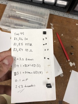
List of components:
- 1x ATtiny45
- 2x 1k ohm resistors
- 2x 499 ohm resistors
- 2x 49 Ohm resistors
- 2x 3.3v diodes
- 1x red LED
- 1x green LED
- 1x 100nF capacitor
- 1x 2x3 pin header
- I vinylCut some 4 layers of vinyl and placed it at the bottom of the PCB so it sticks in easily as a USB and I covered the USB head with some solder to make it thinker. This made it much easier for the USB to connect to my computer
Step 3: Program the PCB and Un-bridge it
I programmed my PCB, unbridged the last unneeded connection. The board programmer works (update: I used it in my future projects) !!
#02 Computer-Controlled Cutting
Building a Modular Robot
Introduction
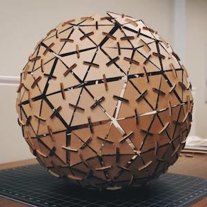
In this week, our assignment was two fold: (1) cut something on the vinylcutter and (2) create a laser-cut cardboard press-fit kit. For the vinylcutter part, I chose to create a cool durable laptop sticker. As for the laser-cut assignment, after researching what type of press-fit kits are out in the market, I noticed that many cardboard kits are designed to build a single figure or multiple restrictive figures as the one shown below. Attempting to defy that restrictiveness, my goal for this week was to create a kit that has many degrees of freedom such that you can build regular geometric shapes, interesting buildings, and even cool ROBOTS with it!
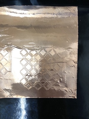
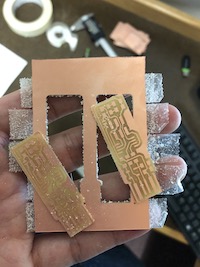
Part 1: Vinylcutter
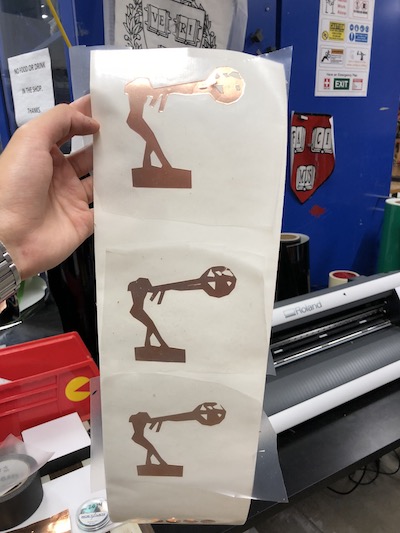
I’ve always been inspired by Lorenzo Quinn’s impressive and meaningful statues, especially his ‘Force of Nature’ Collection (shown below).

I wanted to Vinylcut the image of this statue, but the issue is that the fab mods vinylCutter program didn’t simply do the outer sketch of the image properly given that the image had different colors in it. Therefore, I used photoshop to fill in the interior of the status with the color black, excluding all interior designs and shadings. Then I exported the new image to mods and easily cut it.
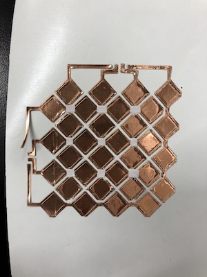
For picking what material to cut on, I wanted to give my sticker a ‘fancy statue’ feeling, so I chose to cut it on a sheet of copper. To do so, I had to stick the copper on a piece of vinyl (otherwise the vinyl cutter peels the copper off while cutting and destroys your cut), then cut combo of vinyl and copper on top of it. After that, I peeled off the excess copper and used transfer tape to transfer the copper off of the vinyl and onto its final destination. The cut looked great!
Part 2: Laser Cutting
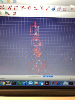
In creating my press-fit kit, I used FreeCad to design my parts.
- Download FreeCad from HERE
- Amazing FreeCad Tutorial is HERE - go over this tutorial before you get started
I really like FreeCad, it’s free, simple to use, and really powerful!
Part 2.1: Shaping and Sizing
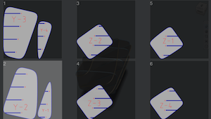
Triangles are cool - really cool - so I decided to start my kit with a set of triangles as the building blocks and several shapes of connectors that allow several degrees of freedom. As you can see below, I made some designs in FreeCad and laser cut them.
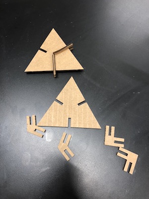
The first connectors I made were pretty good, I had a 180 degree, a 90 degree, and a 120 degree connector with a 3.7mm (width) press-fit sides. The fit was great and pieces connected together well. However, it was hard to initially get two pieces to connect as I didn’t have kerfs in my designs, which also made the connectors frequently break. In my second iteration, I added kerfs and made the triangles and connectors more compact (shown below).
The pieces finally connect smoothly now and their size was just right. Additionally, the kerfs mad the pieces much stronger!
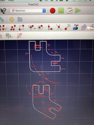
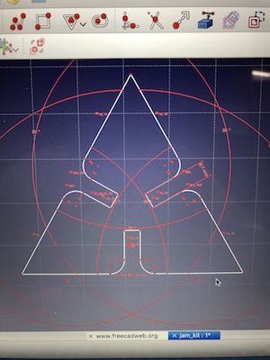
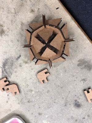
Now that I had all the sizing and fitting sorted out, I decided to create more connectors that give me even more degrees of freedom. At this point, I thought to create a gear that is 45 degrees from each hole such that you can have many angles to connect with it from. Below is my final kit pieces.
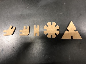
(left to right)
- 120 degrees connector
- 90 degrees connector
- 180 degrees connector
- general connector, 45 degrees from each whole
- triangle building block
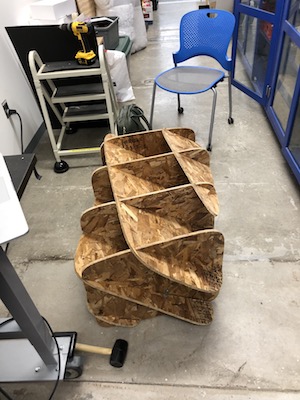
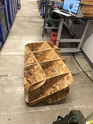
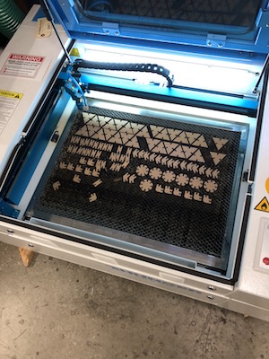
Part 2.2: Mass Cutting and Building
Now that I have my tested final kit, I went ahead and printed a bunch of pieces so I can start assembling them into something cool.
Then I decided to build a mini transformer ROBOT… or a penguin (why are people saying it looks like a penguin??).
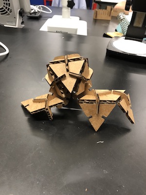
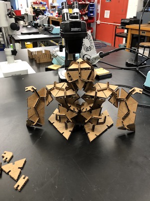 !
!
UPDATE: I should have made the fit holes even tighter, after a month of having the statue dangle on my desk it started to fall apart!
Files:
- DXF parts HERE