Resources


Creating a GPS LED Development Board

Context

The assignment for this week seemed simple enough. Make a new board (which I've done before) incorporating a sensor (which I've done before, if you count the button on my RGB LED board) and read it (which I've done before with my LED). With this feeling of confidence I decided to tackle some of the technology I'll need for my final project, namely a GPS module. I decided to combine this week's assignment with next weeks, to create a development board which would allow me to test both the GPS module and the LED light pixels I was planning to use.

Little did I realize the Pandora's box I was opening. What followed was a lengthy investigation into datasheets, example code, and unraveling unforseen challenge after challenge. I found myself slipping precariously down a rabbit hole of research which quickly became overwhelming in its depth, though in hindsight I'm glad I went through this investigation at this stage.

This page outlines my research, leading to the design and fabrication of a GPS LED development board.

GPS Research

After some poking around, I settled on the Adafruit Ultimate GPS Module and corresponding breakout board for development testing. This module includes a built-in antenna and some other nice features like internal data logging, though it isn't cheap - mine cost around $30.

Turns out GPS devices speak in "NMEA sentences," which tell you all sorts of things in a comma separated list. Some sentences tell you about the satellites you're talking to, some tell you where you are, some tell you how fast you're going and where you're headed, and just about all of them include the time (in UTC).

There are a number of libraries out there for parsing these NMEA sentences, including one made by Adafruit specifically for their GPS module for use in the Arduino ecosystem. TinyGPS and TinyGPS++ both include some additional handy tools, such as determining direction and distance to any other latitude and longitude on the globe, which is rather non-trivial.

Unfortunately, these libraries can get large and take up considerable memory space. David Johnson-Davies mentions on his Technoblogy blog that with all its bells and whistles, the TinyGPS library is too big for an ATtiny85. I started looking into upgrading to members of the ATmega family for my final project, but I'll use an ATtiny84 to start working with these components beforehand. Ideally, I'd like to replicate David's TinyNav Simple GPS Navigator using my own LEDs and configuration.

One last note: this GPS module is picky when it comes to its power supply. It's rated for between 3v and 4.3v, making a standard 5v supply too hot and a typical CR2032 coin cell (which I'd been planning to use for my final project) too cold, as it starts at 3v and subsequently dips down to 2.7v or less. I'll likely look into LiPo batteries for my final project which seem to operate within the GPS module's sweet spot, but for the time being I'll plan to make use of the GPS breakout board's onboard 3.3v regulator.

LED Research

I decided to purchase Adafruit's DotStar LEDs for my project, specifically the APA102-2020, which are all of 2mm square each. These RGB LEDs contain internal PWM and can be daisy-chained together while remaining individually addressable from a microcontroller. While it's possible to use charlieplexing with RGB LEDs to limit the number of pins needed, and while there do exist LED-driving ICs to make your life easier, routing the traces for these feels like it'd be a nightmare and a half. That said, these may be the route I take if I determine that the 2020 package is still too big for what I have in mind.

These LEDs use a SPI-like interface, and are intended for 5v operation. David Johnson-Davies used these successfully with a 3v coin cell battery, and while he mentions that at 3v the blue LEDs are noticeably dimmer, they still seem to function fine. As such, I bet I could use them with a 3.3v or 4v battery for my final, though I'd like to test this first on my development board.

Lastly, I'm a bit concerned about the current draw of these LEDs. They say they draw something around 60mA each (20mA for each color), though this assumes they're operating at full brightness. I'd like to test what current draw one of these LEDs has under my use cases.

Designing the
Development Board

Here's what I want to test/attempt with this development board:

  • What do these LEDs look like on 3.3v?
  • What do these LEDs look like on 5v?
  • What's the power/current draw of one LED?
  • Use a microcontroller to talk to the LEDs
  • Use a microcontroller to talk to the GPS module
    • Parsing sentences
    • Reading the time
    • Using the GPS's Pulse Per Second (PPS) output signal
  • Attempt to recreate David's TinyNav Simple GPS Navigator using the DotStar LEDs

For simplicity's sake (and because these GPS modules are expensive) I plan to use the GPS breakout board and connect to it via jumper wires. This will also give me ready access to a 3.3v power source, using the breakout board's onboard voltage regulator. I intend to use the individual, surface-mount GPS component in my final, and Adafruit provides a reference schematic for the breakout board which I can selectively recreate when needed. The GPS module datasheet also has recommended component configurations.

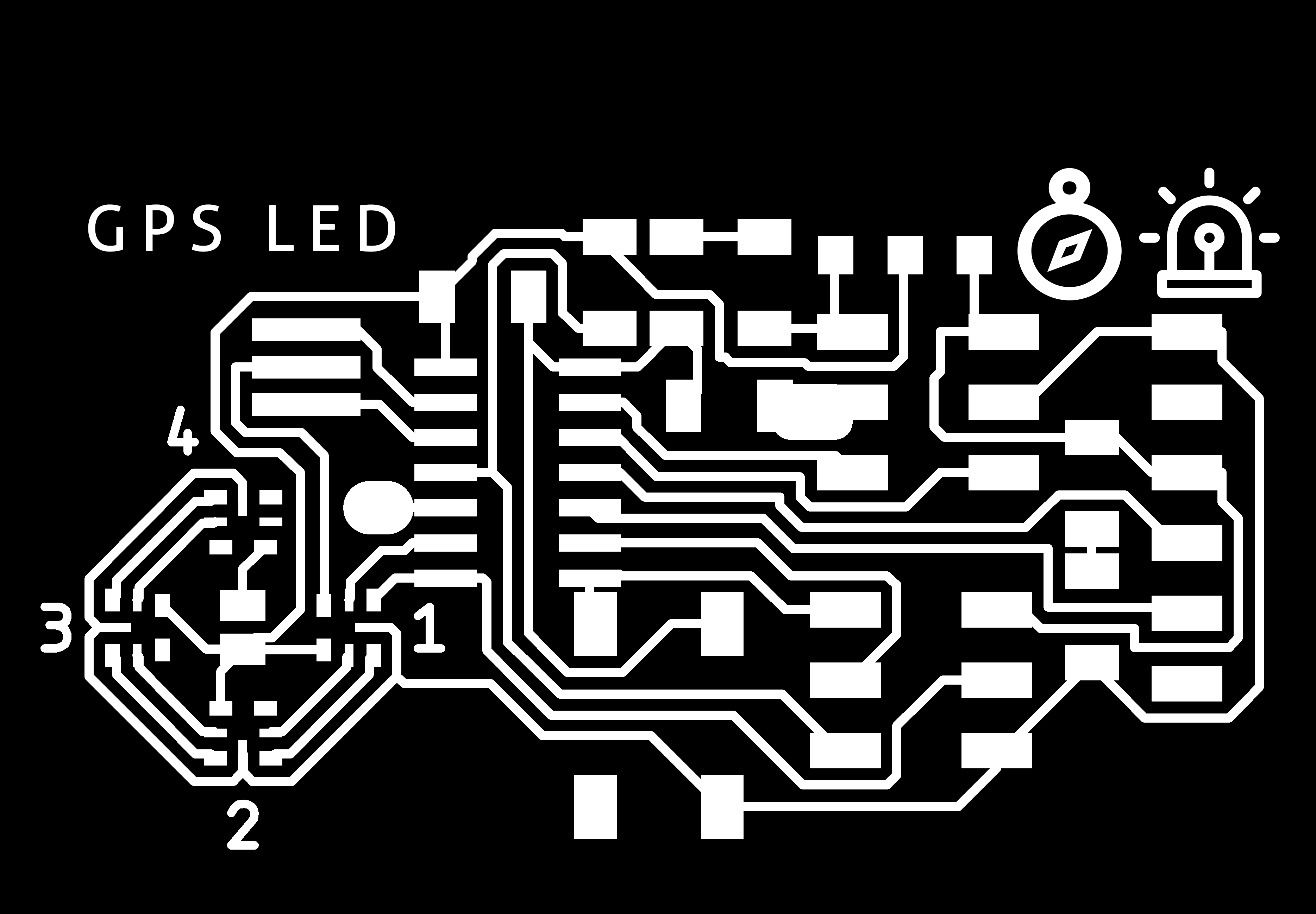
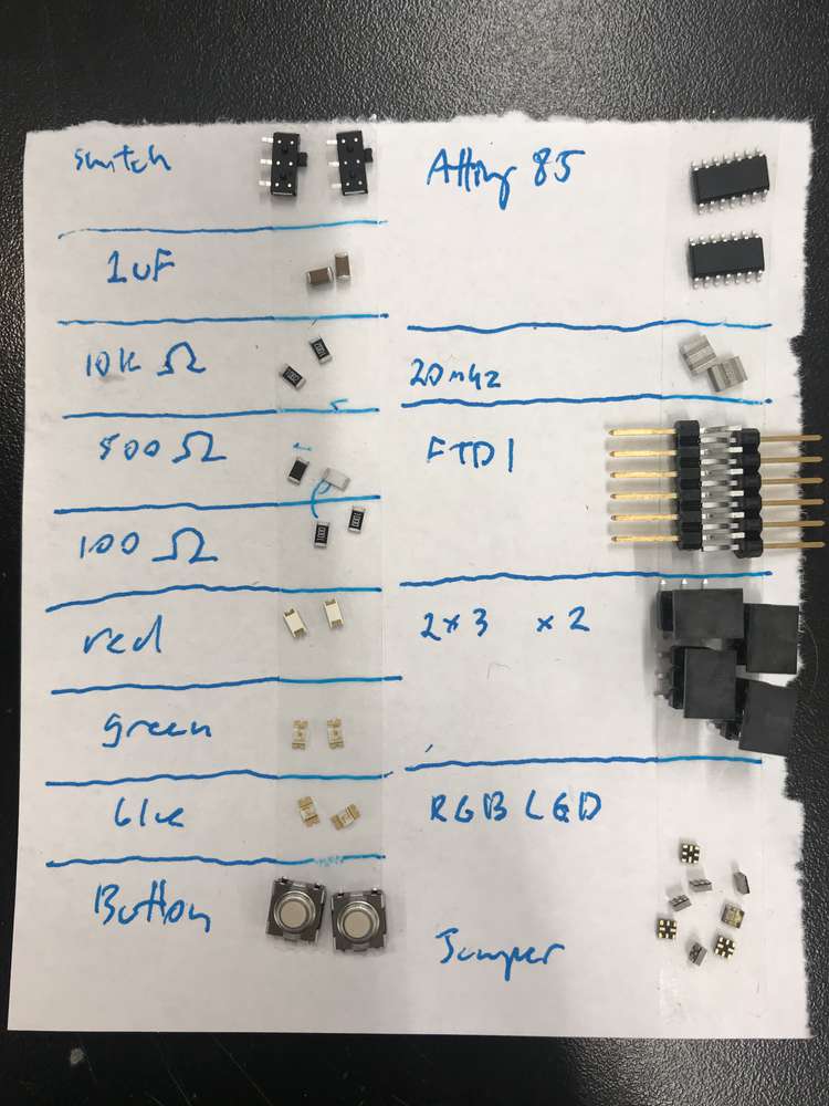
I'll plan to use four DotStar LEDs for this board, just enough to test with something akin to a compass rose. I'll put a solder jumper between the power connection for one of them, which I can use to sample current draw for that LED with a multimeter.

I'll use an onboard switch to toggle between 5v supply and 3.3v supply (the latter taken from the GPS breakout board). This will let me test how the entire system operates on 5v vs. 3.3v.

Lastly, I'll include an LED to indicate the PPS signal, and a button for some simple interaction.

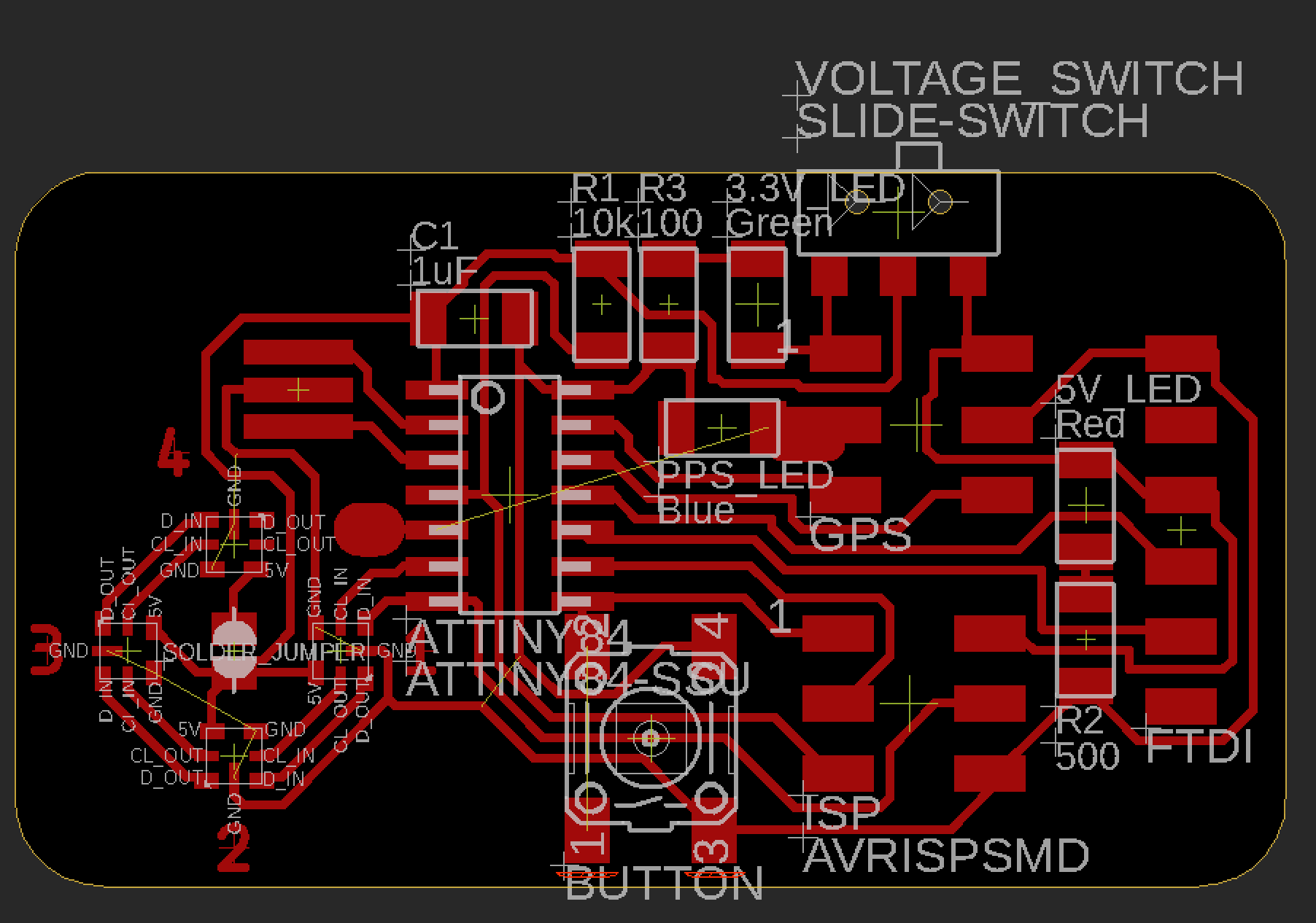
I wanted to include power indicators which toggled depending on which power source was being used - that is, a red LED would be on when 5v were supplied to the components, and a green LED would light when 3.3v were displayed. However, I couldn't figure out how to do this, and resulted to two power indicators which would simply show whether or not each voltage supply were available.

Routing this was super challenging. After several attempts, I was able to get almost everything onto a single-sided board, but needed one jumper wire for the PPS signal. You can view the schematic here.

I was able to find a library for Eagle which included the APA102-2020 footprint, though the pads are so small and so close together that I needed to modify it in order to mill it using our standard end mills. It also lacked connections to the center pads, so I added one of those as well.

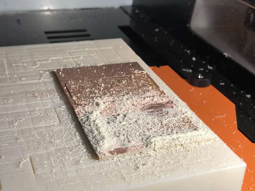
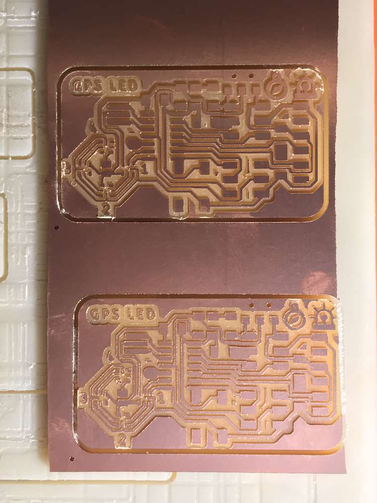
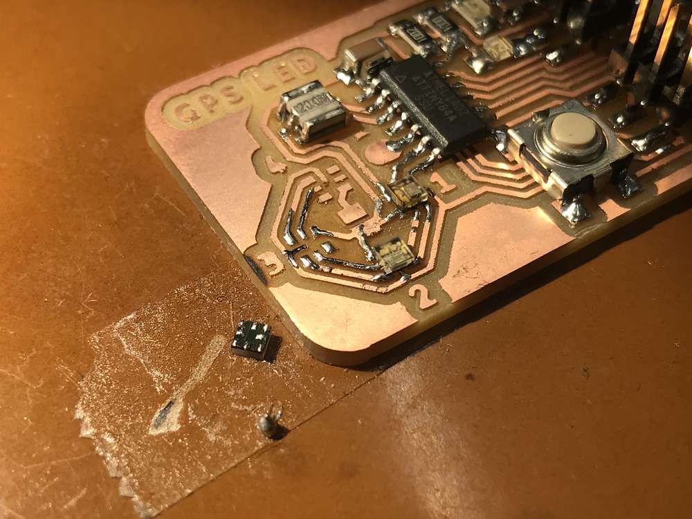
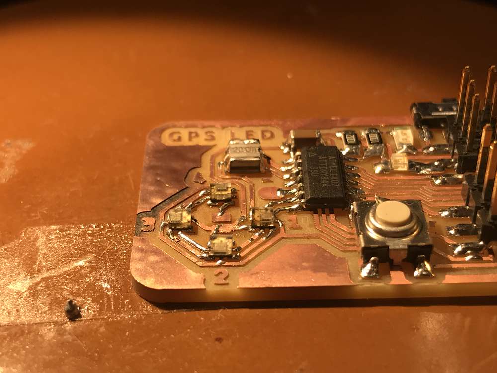
Fortunately, milling the board went smoothly (aside from a slighly clipped edge on one of the copies).

Stuffing the board was another story, mainly due to the super tiny DotStar LEDs. Tinning the LEDs was kind of fun, though super delicate and tedious. I applied a tiny bead of solder to the tip of the iron, and kind of rolled it around the back of each LED. The solder would stick to the pads and the surface tension caused it to hug each pad rather than cover the entire surface. I tinned the pads of the LEDs, tinned the pads on the board, placed the LED on top (surprisingly challenging to align even with tweezers), and used the heat gun to melt it into place. Sometimes the air from the heat gun would cause the LEDs to blow away before the solder melted. When it worked, the LED would slide into place like it was meant to be. When it didn't, the clear casing on the top of the LED got burnt to a crisp. As it was, the heat from the gun burnt the tops of my boards. Nevertheless, it seems like everything is now connected in place.

You can continue to Part II, here.