Final Project: Electric Roller Skates (or skate in this case)
Roller Skate with Encasing
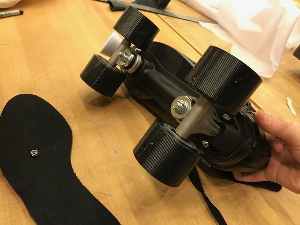
Figure 1. Taking out the #10-32 hex nuts to remove the shoe from the skate plate.
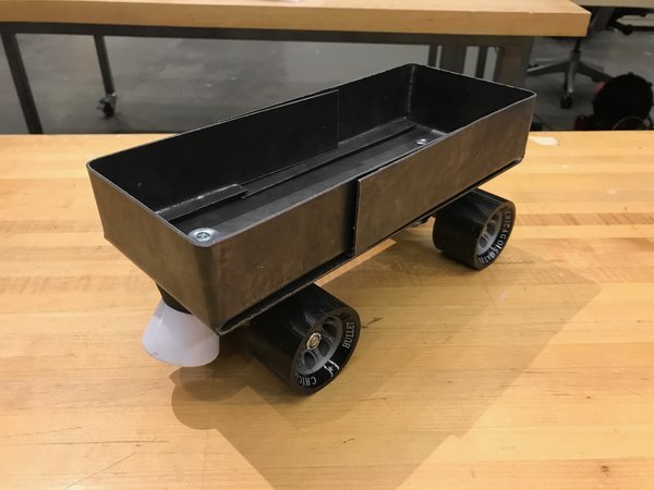
Figure 2. Attached the sheet metal encasing I made in Week 13 to the roller skate plate.
Scavenging for Electronics
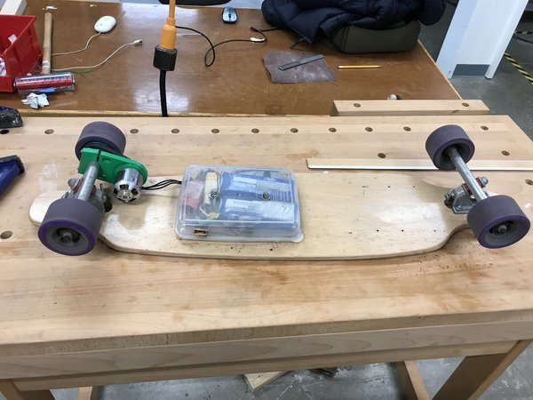
Figure 3. Getting my roommate's old electric skateboard to scavenge for parts (mainly for the belt, pulley, and battery).
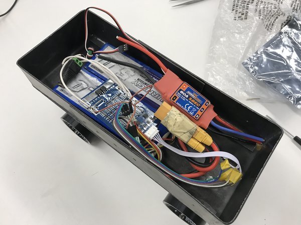
Figure 4. Stuffing all the electronics into the encasing to see how it fits.
Making the Wheel Pulley for the Belt Drive
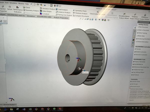
Figure 5. Modifying the CAD file for the wheel pulley to fit my specs (thank you McMaster-Carr) .
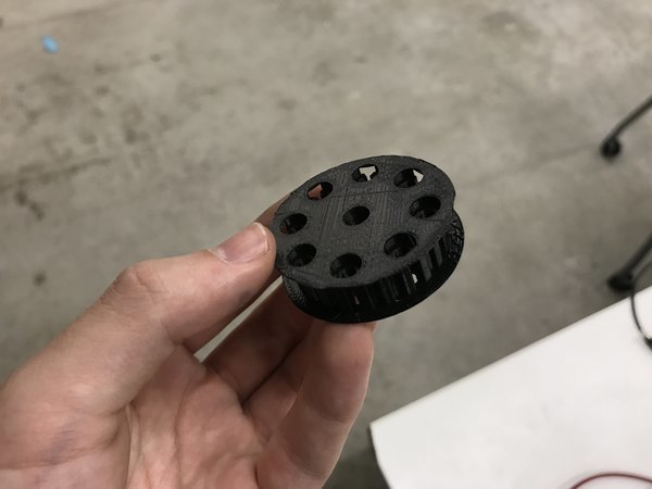
Figure 6. 3D printed wheel pulley with screw holes that go through the wheel.
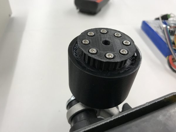
Figure 7. Testing to see if screws go straight through the wheel holes, only to find out that I forgot to change the diameter of the inner hole for the roller skate truck :O.
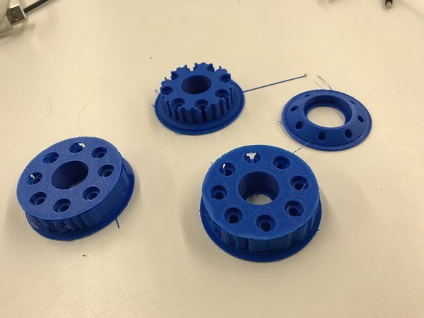
Figure 8. Different 3D printed wheel pulley versions and washer for the other side of the wheel.
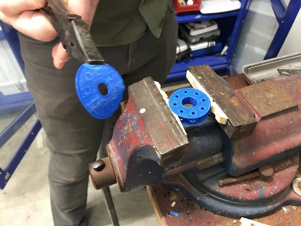
Figure 9. Peeling away the support material using a clamp and clothespin #innovation.
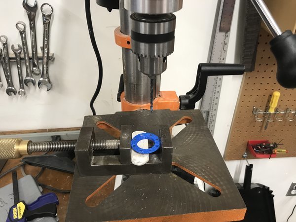
Figure 10. Using the drill press to make bigger holes so that the #6-32 bolts can fit (the clothespin is useful again).
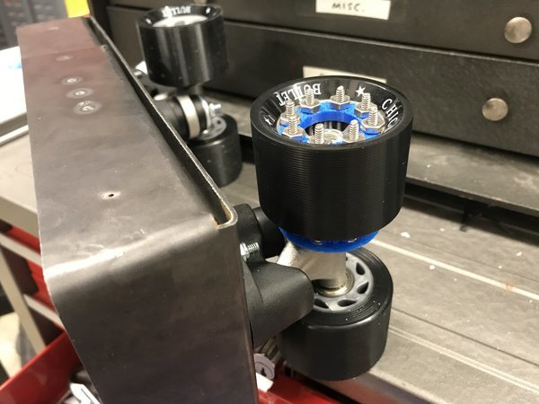
Figure 11. Doing an assembly of the wheel with the wheel pulley and washer.
Testing Motor and Amazon Prime
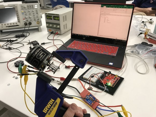
Figure 12. Testing the 580kv motor with the 80A ESC.
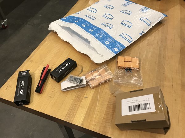
Figure 13. Amazon Prime 2-day shipping came in clutch with the XT90 connectors.
Back to Sheet Metal and FabLight: Encasing Cover and Motor Mount
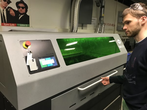
Figure 14. Getting the FabLight to work with Ivan.
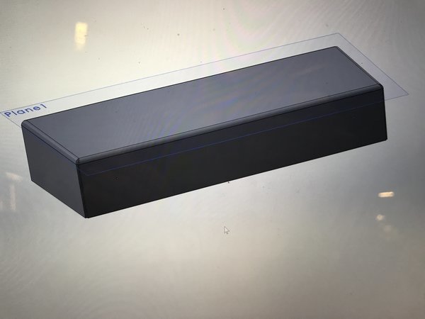
Figure 15. Designing the encasing cover on Solidworks based on the encasing that I had made in Week 13.
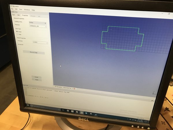
Figure 16. Layout of the sheet metal encasing cover on FabCreator.
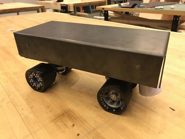
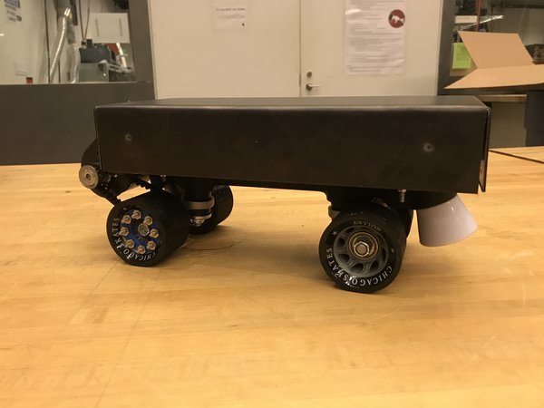
Figure 17. Roller skate with finished encasing.
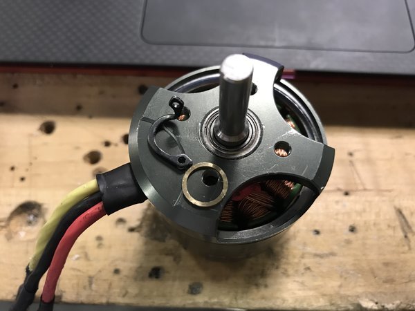
Figure 18. Removing the circlip from the drive shaft so I can put the motor mount.
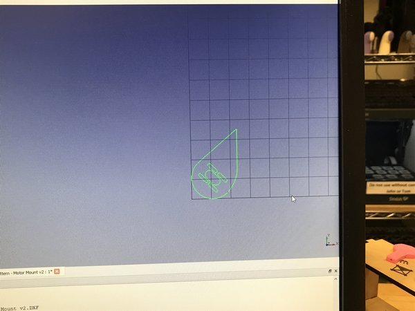
Figure 19. Designed a sheet metal motor mount to cut on the FabLight.
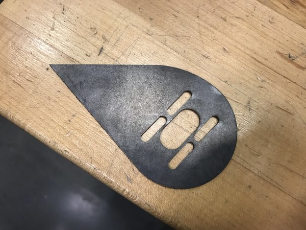
Figure 20. Finished sheet metal motor mount!
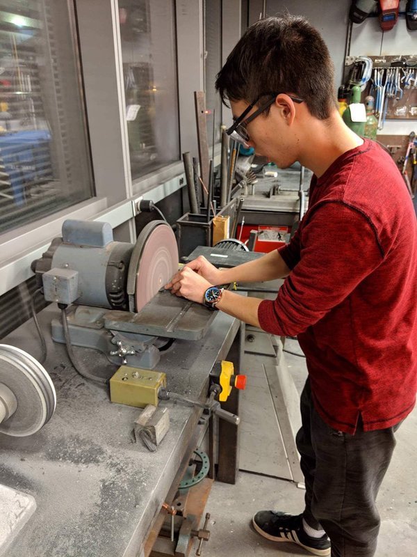
Figure 21. Using the disc sander to make the edges of the metal smooth.
Welding and Problem Solving
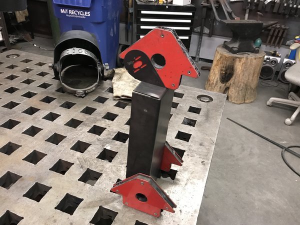
Figure 22. Using the metal blocks to hold my piece and the sheet metal mount in place to weld.
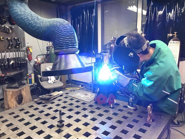
Figure 23. Welding the sheet metal mount onto the encasing.
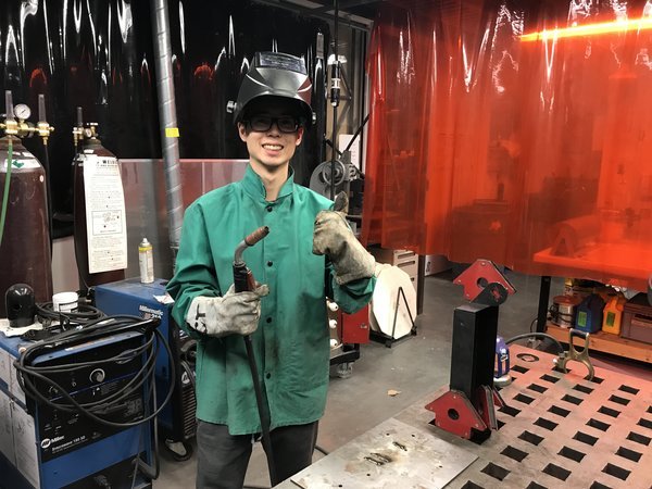
Figure 24. Welding was successful!
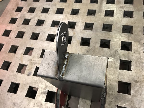
Figure 25. Welding could've looked nicer but it was my first time welding an actual part onto another!
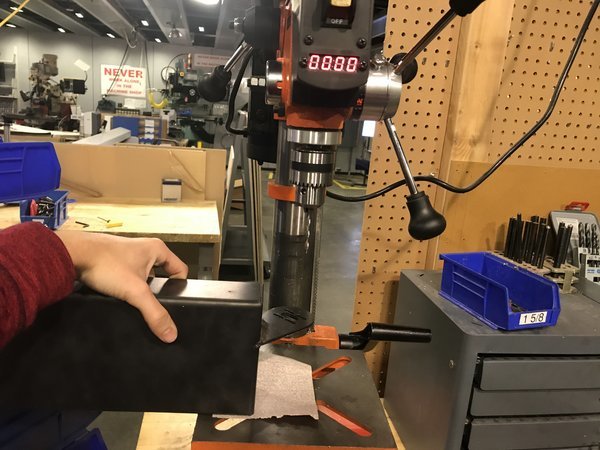
Figure 26. Using the drill press to shave off a little of the metal since the holes of the two motor mounts didn't align by less than a millimeter.
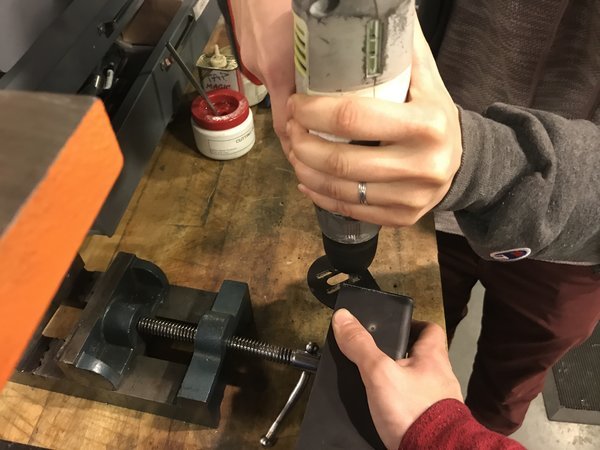
Figure 27. Since the drill press didn't work, I had to use the hand drill. Thanks for helping me Elena!
Assembly and Testing Failures
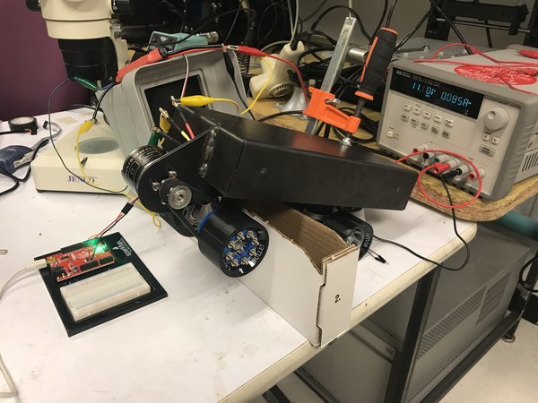
Figure 28. Getting ready to test my mounted motor belt drive system with the power supply!
Figure 29. ...And it doesn't work because the power supply can only supply up to 1 amp which is not enough for the motor to run (I realized this later).
PCB Design, Milling, and Soldering (aka more problems)
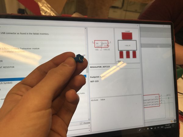
Figure 30. I used a regulator for my EAGLE schematic since the shape and size is very similar to the potentiometer I was using, and I couldn't find the pot component in my EAGLE libraries.
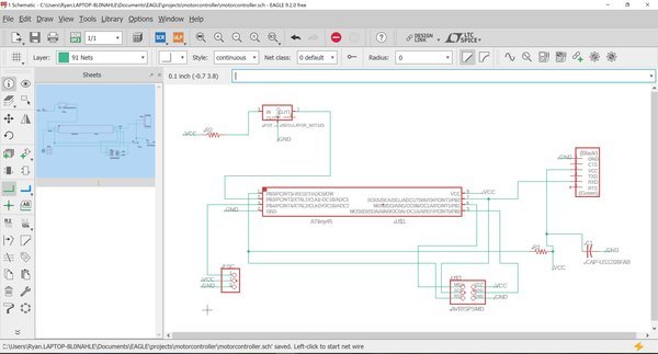
Figure 31. Finished EAGLE schematic with the potentiometer and output for the ESC.
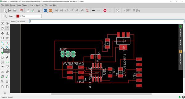
Figure 32. After a long time making the traces, here is my complete EAGLE board.
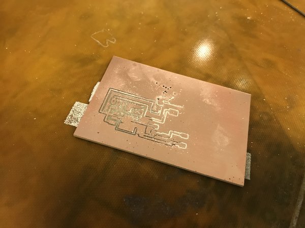
Figure 33. Failed PCB since the endmill started making holes at the top.
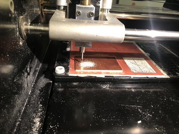
Figure 34. Running the Roland SRM-20 again to make the PCB.
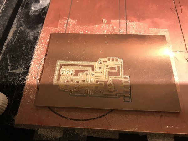
Figure 35. PCB turned out fine other than the traces being a little thin, but the mill made 2 holes insted of 1 where I was supposed to insert the ESC's cables. This means that the copper traces are broken.
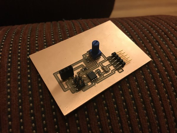
Figure 36. After fixing and soldering, here is the final PCB for my wired remote controller!
Charging LiPo Battery and More Soldering
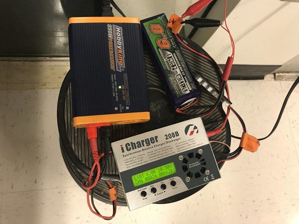
Figure 37. Luckily found a LiPo charger and new batteries so that I can test my roller skates. (Thank you so much to Laura Perovich from Object-Based Media for letting me borrow all of this!!!)
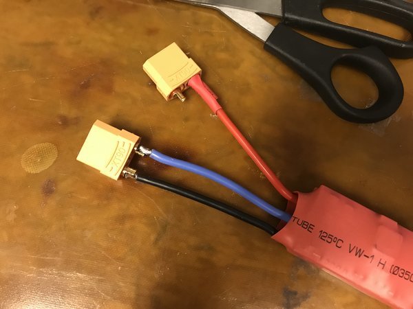
Figure 38. Soldering the XT-90 connectors to the ends of my ESC to plug into the motor easier (the bane of my existence for this project; more on this later).
Finished Prototype!
Figure 39. Running the electric roller skate with my pot remote controller. Success!