
Week 12: Networking and Communications
The Task
Design and build a wired &/or wireless network with addresses connecting at least two processors
My Idea
As with last week, I wanted to keep working on my final project. Because the Adafruit GPS module that I am using contains a processor (ARM7EJ-S CPU), communication between the GPS module and a microcontroller board constitutes communication between two processors and so for this week, I decided to make the board that I will be adapting for my final project.
Board Design
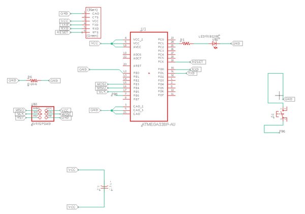
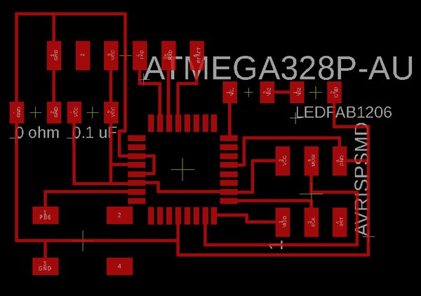
I am planning on using an Atmega328P as the microcontroller for my board. This is because there is I need the extra pins that it offers (tinies don’t have enough) and the extra program memory (GPS module takes up a decent bit of memory and the 328P has 32KB).
For this week, I basically made my board as simple as I could. I have an LED, button, and then the rest is the bare minimum that is needed for the board to run. In the future, I will have the 350mAh battery that I am planning on using hooked up via a JST 2 pin connector - however, that is still coming in the mail.
Further, because the GPS modules are so expensive and I think I already broke one, I’m still hooking things up to the Ultimate GPS Breakout Board for now. After talking with Rob, I realized that I can reuse the 2x3 header used to bootload the board in order to communicate with the board, since it has pins for VCC, GND, MOSI, and MISO (the latter two can be used for RX and TX, according to Rob).
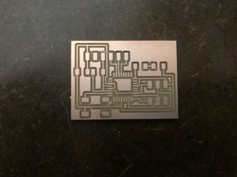
My boards are below:
Board Creation
Milling
This week was the hardest week yet for me for milling. At first, I used the default settings for the fill, which sets a tool diameter of 0.39624mm. This resulted in a board for which the pads for the ATMega328P were simply not cut - the setting wasn’t find enough to create a toolpath that cuts in between where the pads are supposed to be.
I thought that this might be a fluke and tried the same settings again. Then, I tried with a tool diameter of 0.005 and an offset of 1. Next came 0.17 tool diameter, for which I also tried different endmills.
Finally, Victoria gave me the great advice of trying 0.25 tool diameter with the default offset of 2 (For those of you that don’t know as I didn’t, offset determines the number of times that each path is repeatedly cut).
Also, note that the changes in these settings should occur in “Mill Raster 2D”, not “set PCB defaults” (which should only be related to the properties of the endmill used itself).
Here are some failed boards, a sample of the total of 5 failures that I had.
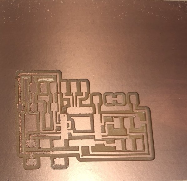
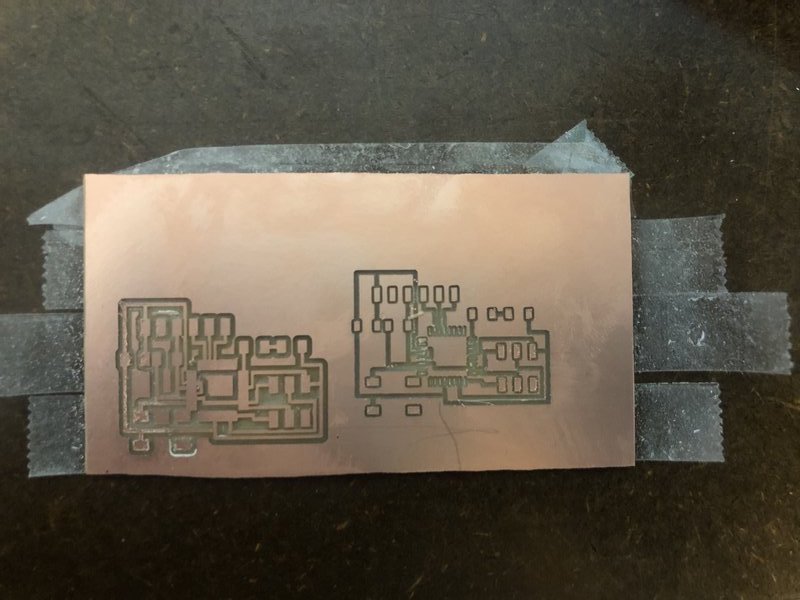
And my final success!
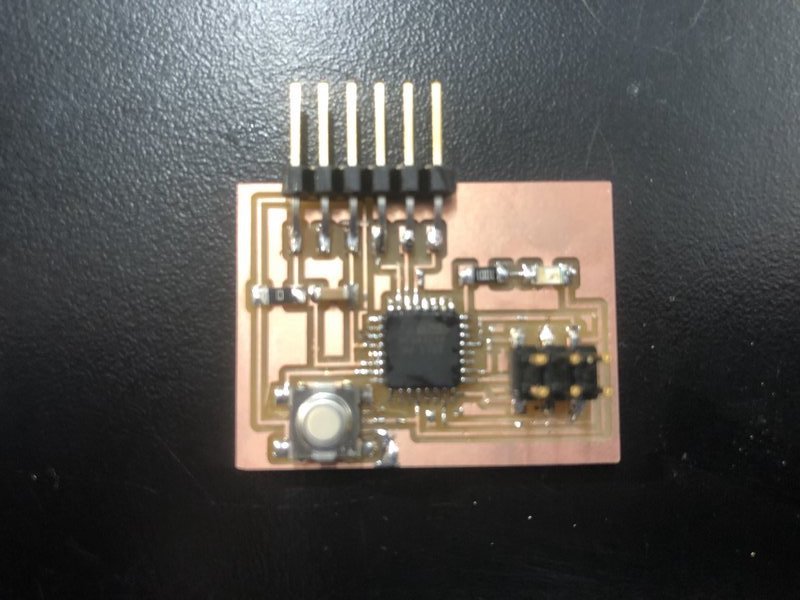
Soldering
Soldering this week was relatively straightforward - one thing to be aware of is just how close the pins are in the ATMega328P. It’s easy to connect the solder between two pins by accident - the good advice that was given to me was to use the solder wick on the area of the connection - it usually takes away all the excess solder and actually leaves the pins nicely soldered to the pads!
Tada!
Programming
This week was a nightmare for programming as well. The gist of the story is just that I was unable to figure out why my programmer is not programming my board. I am currently troubleshooting. However, the good news is that I have all of the code written and I ended up testing it on an Arduino Uno, where it works. The only step that needs to happen is connecting the GPS breakout board with my board using the serial bus.
The Code:
#include <Adafruit_GPS.h>
#include <SoftwareSerial.h>

const int led_pin = 1; // analog pin, will probably change in new board design

SoftwareSerial mySerial(0, 1);
Adafruit_GPS GPS(&mySerial);

// Set GPSECHO to 'false' to turn off echoing the GPS data to the Serial console
// Set to 'true' if you want to debug and listen to the raw GPS sentences
#define GPSECHO  true

// this keeps track of whether we're using the interrupt
// off by default!
boolean usingInterrupt = false;
void useInterrupt(boolean); // Func prototype keeps Arduino 0023 happy

void setup()
{
  // connect at 115200 so we can read the GPS fast enough and
  // also spit it out
  Serial.begin(115200);
  while (!Serial);
  delay(10);
  Serial.println("Adafruit GPS logging start test!");

  // 9600 NMEA is the default baud rate for MTK - some use 4800
  GPS.begin(9600);

  // You can adjust which sentences to have the module emit, below
  // Default is RMC + GGA
  GPS.sendCommand(PMTK_SET_NMEA_OUTPUT_RMCGGA);
  // Default is 1 Hz update rate
  GPS.sendCommand(PMTK_SET_NMEA_UPDATE_1HZ);
//  GPS.sendCommand(PMTK_SET_NMEA_OUTPUT_OFF);
  // Sets 5 second logging interval
  GPS.sendCommand("$PMTK187,1,5*38");
  // the nice thing about this code is you can have a timer0 interrupt go off
  // every 1 millisecond, and read data from the GPS for you. that makes the
  // loop code a heck of a lot easier!
  useInterrupt(true);
  delay(10);
  Serial.print("\nSTARTING LOGGING....");
  if (GPS.LOCUS_StartLogger())
    Serial.println(" STARTED!");
  else
    Serial.println(" no response :(");
  delay(10);
}

void loop()                     // run over and over again
{
  // displays statistics
//  GPS.sendCommand("$PMTK183*38");
//  delay(10000);
}

/******************************************************************/

// Interrupt is called once a millisecond, looks for any new GPS data, and stores it
SIGNAL(TIMER0_COMPA_vect) {
  char c = GPS.read();
  // if you want to debug, this is a good time to do it!
  if (GPSECHO && c) {
#ifdef UDR0
    UDR0 = c;
    // writing direct to UDR0 is much much faster than Serial.print
    // but only one character can be written at a time.
#else
    Serial.write(c);
#endif
  }
  if (Serial.available()){
    char command = Serial.read();
    // dump data
    if (command == 'd'){
      GPS.sendCommand("$PMTK622,1*29");
    }
    // erase all data
    else if (command == 'e'){
      Serial.println("erasing");
      GPS.sendCommand("$PMTK184,1*22");
    }
  }
}

void useInterrupt(boolean v) {
  if (v) {
    // Timer0 is already used for millis() - we'll just interrupt somewhere
    // in the middle and call the "Compare A" function above
    OCR0A = 0xAF;
    TIMSK0 |= _BV(OCIE0A);
    usingInterrupt = true;
  } else {
    // do not call the interrupt function COMPA anymore
    TIMSK0 &= ~_BV(OCIE0A);
    usingInterrupt = false;
  }
}
EDIT:
Again, this was completed for the final project when I got two boards, both made by me, to communicate with each other, one a vanilla 328P that I made and one a board with a GPS module on it! See here.