Computer-Aided Design
Final Project Concepting
9.12 - Initial Idea: I want to find a way to reduce the carbon emissions and plastic waste from
Consumer Packaged Goods through a concept I'm calling "Last Mile Liquids" - consumers buy would-be
liquid products (for home care and personal care) in concentrate form, adding the water (which is conveniently piped to every house!) at home.
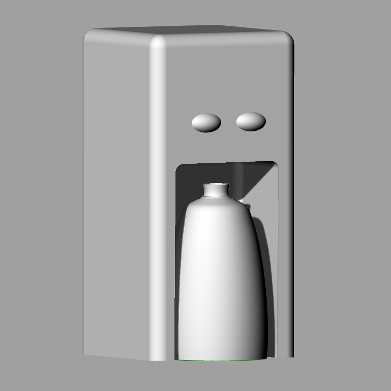
I made an extremely simplified model of a small home appliance that would allow someone at home to easily mix or "print" their own liquid products.
Last Updated 10.24 - Pivoting: I have since combed through a lot of ideas for the final project. I have thought about making a pneumatic compression garment,
a programmable knitting machine (this would have to be with partners), and a pilates reformer that can monitor and help me correct my alignment. (While I'm hanging onto the
pilates idea and doing some side research in case I change my mind again,) I have come to the conclusion that it would be smartest to work on a prototype that I
am designing as part of my thesis project.
With the same intention as the Last Mile Liquids concept above of reducing the carbon emissions and plastic waste from Consumer Packaged Goods,
I am developing a concept for a package-free micromarket for apartment buildings - offering flexible portions of staple dry goods, personal & home care items at bulk prices.
If people are familiar with what a package-free store is,
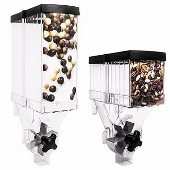
they often have big bulk gravity dispensers that allow customers to purchase as much or as little as desired
(rather than prepackaged, preportioned amounts), reducing product waste, and reducing the unit price (because sourced in bulk, not paying for the fancy labels).
Customers are strongly encouraged to bring their own refillable containers.
These sorts of shops work in other countries in Europe, for example, where the zeitgeist for sustainable consumerism is different. US consumers, however, demand convenience
and it is difficult to encourage such refilling of containers. This is why an hyper-local apartment-based version that borrows from the metaphorical vending machine
can hopefully overcome this barrier.
I'm designing large, beautiful, modular gravity dispensers that can be placed in exsiting underutilized spaces in large residential buildings.
The dispensers will have sensors that can detect how much residents dispensed and then charge them (through an app) accordingly. Sensors will also detect when product is low
in a dispenser, which will trigger a new bulk product shipment accordingly. (No staffing necessary, except to refill when empty.)
I want to figure out how to do a hack prototype version of these dispensers so I can start doing some user testing ASAP to validate the concept.
Evenutally I'll work towards the electronics design of the actual prototype.
At the moment my thoughts are that I need some combination of time and weight sensing. It probably makes sense to do optical or continuity sensors to detect the mechanical
"switch" to sense when the user has pulled the lever to trigger dispensing. This is to essentially break the circuit to confirm that a transaction has happened. It is a call to action
or ISR to save energy/reduce current draw.
Then I need to sense weight of product dispensed, which is probably most easily accomplished with delta of weight in the dispeenser. I've come to learn that my options here
are likely an FSR (cheaper, easier, but have to deal with issues such as historesis) or a load cell/strain guage. I was told the cheapest way to buy one of these is to buy a scale on Amazon
and strip out the sensor (look for one that has analog output). I'm thinking this sensor can both detect how much was dispensed (which can then be converted to aount $ owed)
and recognize/notify when the product is low, to trigger a new shipment of product (similar to Amazon dash button).
Then I need a set of sensors to see if the customer has changed. This is most easily done with proximity sensors - either ultrasonic or IR. Here I'm told ultrasonic emitter/detector pair
is better option as the IR tends to finnicky and has more documented issues.
After all this research, I realized that a turn dial dispensing mechanism (wind mill-type idea) that just counts the amount of turns, might be the best option to reduce the most complicated of sensor issues.
With this method, you aren't depending on a sensor (load cell or other form of weigh scale) to do any of the "heavy lifting" to discern the specific volume or weight of material removed--
simply need to keep track of dial rotation, which is relatively trivial and then use this integer number to calculate volume and, in turn, cost.
To sense rotation I've found that I might be able to fix a permanent magnet(s) to the back of the dial and use a hall effect sensor to count the number of times a magnet has passed by.
11.28: Update
I have finally decided exactly what I will be making for my final project. I am adding a paddle sensor to a dilution control device so that I can turn the device, which is typically for commercial use,
into a consumer grade product. The senor is meant to determine how much liquid was dispensed so that I can charge the user for that amount.
I am likely going to 3D print the spindle and a top and bottom casing for the spindle and then use either hall effect (magnetic) sensors or an optical rotary encoder.
So far I've learned that magnetic sensors are cheaper but it would mean that they are touching the liquid.
The optical encoder using an LED and a receiver is much more accurate and no part would be touching the fluid, but it is more expensive and might be more difficult to design for.
If I can, I would love to add to the project and connect my LCD to display how much has been dispensed or "how much is owed".
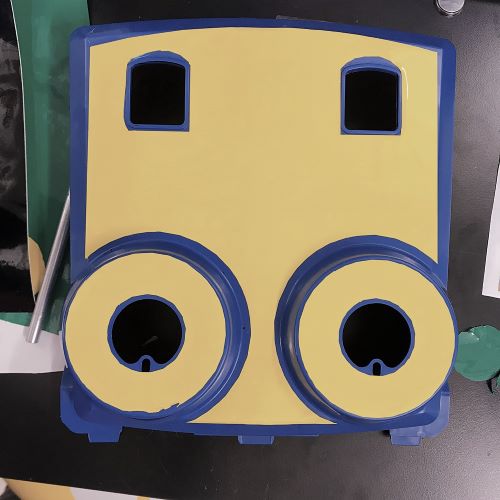
Additionally, since I am adapting an existing device which is quite ugly, I hope to use the composites week to create a different facade. Otherwise, I might mill foam coare and vacuum form (or vacuum
bag + apoxy) a new facade.
12.17: Update
The final project is completed! I ended up with a hall effect rotary encoder on a spindle and paddlewheel, connected to an LCD. Please see the final project page for more documentation and to see how it turned out!
Tools: Rhino

Computer-Controlled Cutting
Viynl Cut Sticker
After playing around with various shapes and images - initially a simple star and a failed attempt at an Albert Einstein sticker - I used the vinyl cutter to make a cute stegosaurus sticker. Some of my friends call me "Baby Dino" so I figured it was appropriate.
Tools: Vinyl Cutter; Vinyl; Copper shee
Computer-Controlled Cutting
Laser Cut Press-Fit Kit
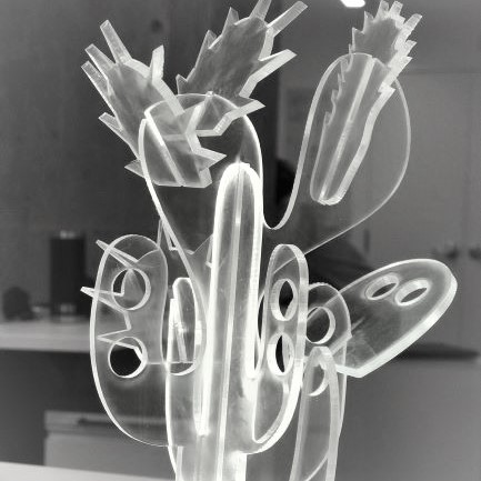
I remembered seeing an adorable cactus earring holder and jewelry display in a boutique recently and thinking to myself: "I could make this", so I decided to! The assignment asked us to made a 3D press-fit kit that could be assembled in a different ways. It was also supposed to have parametric joints so that the entire design didn't have to be redesigned depending on the thickness of the material used.
Modeling the Kit: Using Rhino, I drew out crazy cacti pieces that could attach to a base cactus. I intersected by shapes in 3D space as I would want them to attach. I then used Grasshopper to make the joints and to ensure they would all change parametrically once I decided on the material I was going to cut with. The 'Region Slits' component on GH made my life a lot easier - figuring out the appropriate 'slits' or joints, and then I attached a
slider for the width and added some code to lay all the pieces flat and separate from one another.
Characterizing the laser: With a partner in my section, we characterized the laser for the 1/8" acrylic that we were using.
We made two different sets of combs (one with cuts slightly bigger and slightly smaller than 1/8"; one set with all smaller which turned out to be the right way) to test which would be a snug fit for our joints.
After finding the right parameter, I entered it into my GH slider (.13), baked, and then began the process of laser cutting and assembly.
Tools: Rhino; Grasshopper; Laser Cutter (150 Watt); 1/8" Acrylic, 1/4" Acrylic

Electronics Production
Mill & Stuff a Circuit Board
This week marked the beginning of learning about electronics (yay!). But before we learn about what all the components do and how it all works together, we were tasked with milling and soldering our own circuit board.
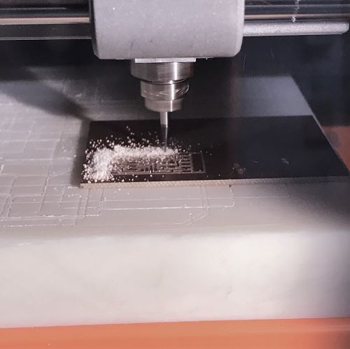
Mill Set-up: We were given a circuit design in PNG form - one for the traces and one for the outline - to be uploaded to the MODs program which controlled the micro-mill (a Roland MDX20(check!)) I taped a copper plated board to the "sacrificial" block in the machine, calibrated the origin, placed the 1/64” bit, and ran the machine.
Milling Mess-ups: As you can see, my first attempt shows that my board was uneven and the bit was too shallow. I figured this could have been because my z value was too large (at 10), my bit wasn't down far enough, and/or the area of the sacrificial block that my plate was on had been depleted unevenly from previous students' cuts. My next attempt went too far in the other direction. I was a bit forceful with laying the bit down on the plate and I lowered the z value to 1 and attempted to have everything evenly flat. As you can see here, too much of the copper was removed.
Milling Success: I realized how much finesse micro-milling requires... the 3rd attempt was Goldilocks - just right! It came down to tightening the bit just right to get the perfect depth. With this same method I was successful on milling the outline with the 1/32" bit on the first try (phew!).
Reading a Schematic & Gathering PCB Components: Once the circuit board was cut, I turned to the board schematic. I gathered all the tiny components (diodes, resistors, capacitor, microcontroller…), taping them to an index card to stay organized.
Soldering/Stuffing: Although I had soldered jewelry in the past, soldering these tiny parts in very precise locations was quite difficult. After practicing on a disposed board for a little, I began soldering on my board. Keeping the part in place and the solder in place while holding the soldering iron was tricky - I was wishing I had 3 very steady hands - but with patience I got all the pieces correctly connected to the board!
Tools: Roland MDX20, MODS, Electronic parts (XX!), Soldering Iron
3D Scanning
Using Handheld Object Scanner
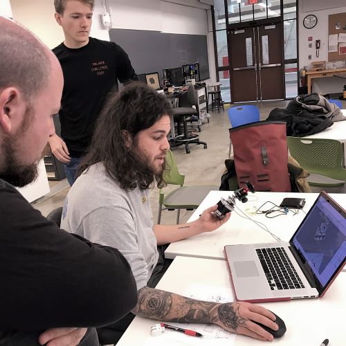
We first learned how to use the handheld 3D scanner by testing on one of my classmates. The scanner has an option for face versus small/medium/large
object and seemed to be calibrated well for faces. His scanned well!
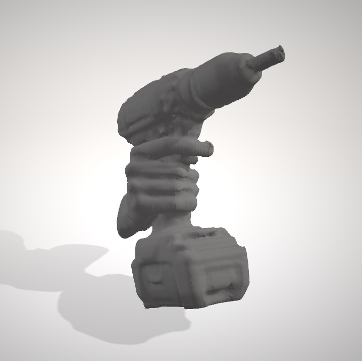
Separately, another classmate and I scanned a drill to test it out for ourselves.
It took patience and a steady hand, but the scan came out -- overall a super simple process!.
Tools: 3D Scanner name(????)
3D Printing
Design 3D Printable Object
(Not Possible Subtractively)
Testing Printer Design Rules :
To complete the group assignment which was to test the design rules for our 3D printer, I worked with a classmate to make a test block. On it, we testing how long, thin, and sloped overhangs could be without warping or collapsing. We tested precision relating to drill hole sizes, curvature, and tolerance for geometries close to one another.
The print took about 3.5 hours to complete, and the template made us realize that the printer didn't have enough tolerance for the small text we incorporated (1-2mm thick). Most of the structural elements were perfectly precise and intact, though there was some warping/cantilevering on the most severe angle tested.
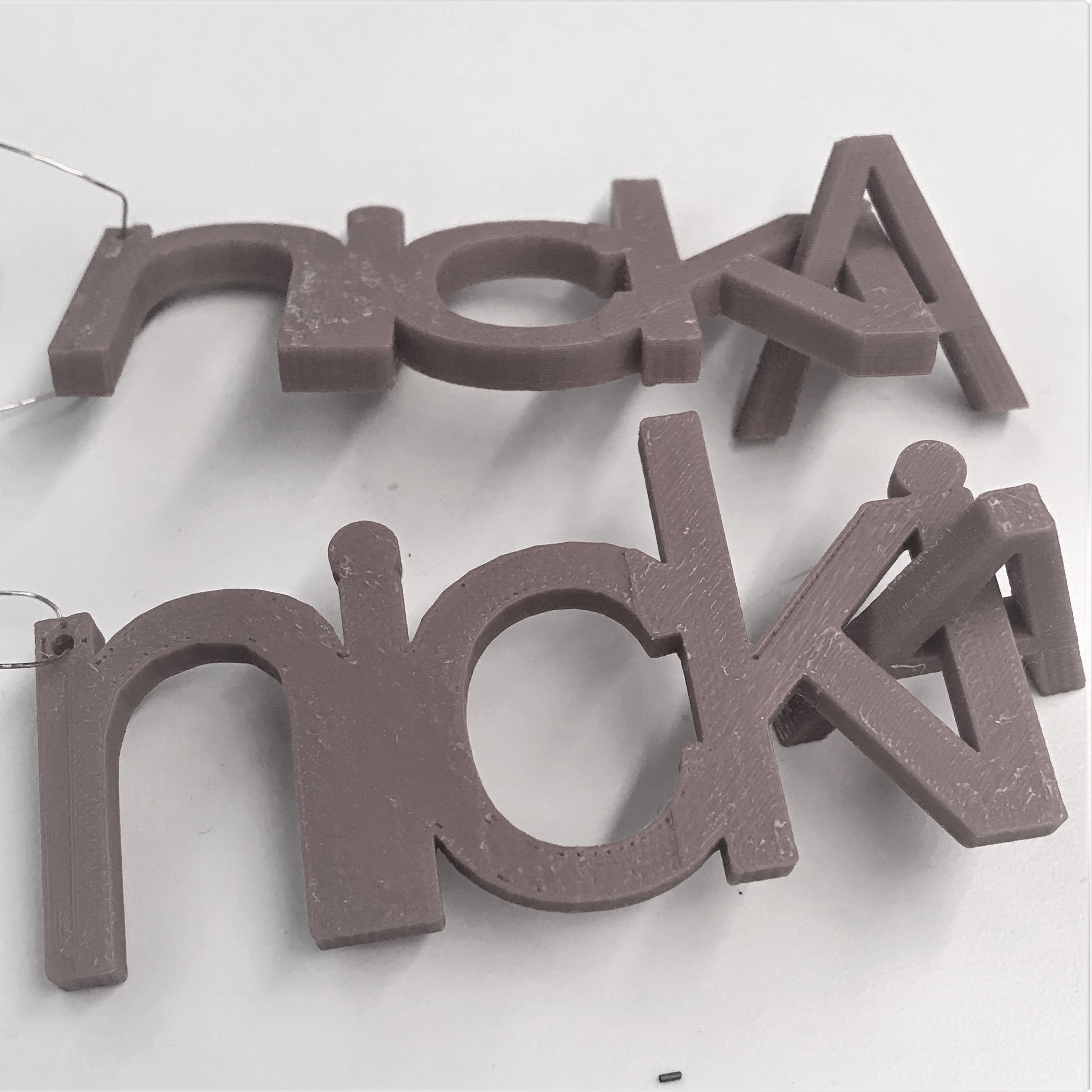
Designing an Object for Additive Printing: There were many options when it came to designing some object that couldn't be easily made through subtractive means. At first I was thinking about interesting joints, difficult-to-mill shapes, snow globe-type concentric objects...but I decided to make two objects that were intersecting and make use of the soluble support material. I was intrigued by the idea of making interesting earrings - something I might wear in the future that could remind me of this class! I thought about doing dangly letters with my initials (NSA) intersecting, but the N and S didn't have enclosed areas.
I ended up spelling out my first name with the letters connecting and then utilized the enclosed part of the A in my last name to intersect the objects in a way that could not be done without the use of a 3D printer.
Tools: Rhino, Dremel PLA printer, Stratasys 1200 (ABS filament)
Electronics Design
“Design"/Make/Test a Circuit Board
Observing Operation of Microcontroller:
As a group this week, we were meant to use the test equipment in the Science Center lab to observe the operation of a microcontroller circuit board. We were introduced to the multimeter and the oscilloscope. Coming into this session having a very elementary understanding of electronics, this time to play around, work through the exercises provided and ask some basic questions, proved quite helpful.
"Design" a Circuit Board: The first step in this week's assignment was to redraw the hello-world schematic using Eagle or an equivalent software, adding at least a button and an LED (I added two to act as different indicators once we program it).
Starting with the example board layout provided and working alongside a few classmates (because I found this process rather unintuitive), I imported the fab library into Eagle and eventually added all the right components onto my new schematic. This took a while and was not very enjoyable. I then moved onto all the placing and wiring. I placed most of my components to mirror what was in the example layout and fit the button and LEDs in empty real estate on the bottom left corner and top right corner on the PCB. My wiring, at Rob's suggestion was at a width of 12 rather than the default 6.
After 20 minutes I thought I had completed my wiring and didn't understand why this step was taking everyone around me so long. I soon realized that I needed a buffer of at least 15 in between wiring and other wiring or components and thus I had to re-do my wiring - this time it was a much more tedious process.
Make & Test Circuit Board: Eventually I had my schematic + my layout and board outline (both as PNGs) so I moved onto milling, assembling, and programing the beautiful PCB. After successfully milling my board (the traces with a 1/64 bit and the outline with a 1/32), I gathered my components and took a look at my board with one of the TFs. We realized that my power/VCC wasn't connected all the way through. For a second I freaked out that I'd have to redraw and remill the board after spending so many hours getting this far, but I was assured that I could make a little jumper wire. With patience I got all the parts soldered, the jumper wire attached, and the board successfully tested.
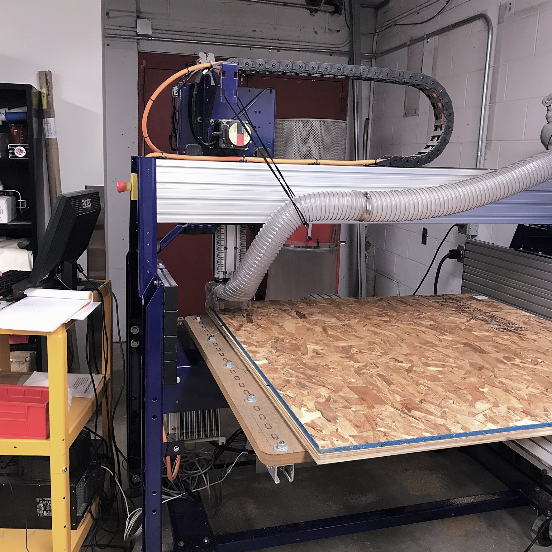
Computer-Controlled Machining
Make Something Big
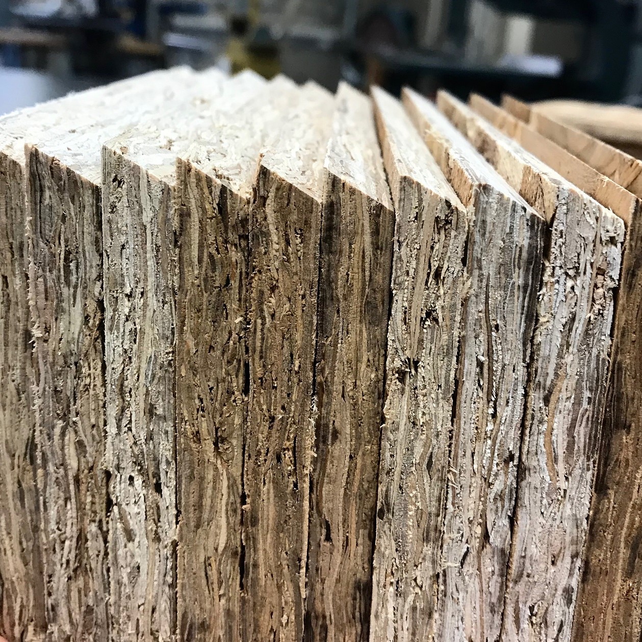
This week’s open-ended assignment was to “make something big”. We were given a couple 4X4 sheets of OSB
(oriented strand board) which was free to use and had a designated times slot to use the CNC ShopBot.
Choosing What Big Thing to Make:
This week has been insanely busy for me, so I wanted to choose a design that was on the easier side to model and assemble, but also something
that I would use – I hate to waste wood and I wouldn’t some big useless item cramping my space!
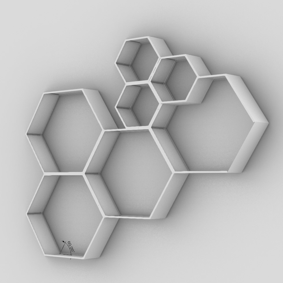
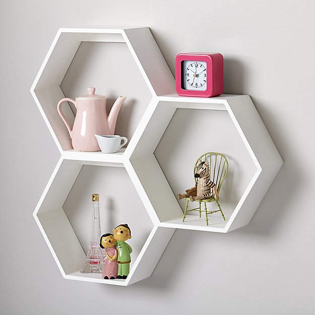
I considered things like a standing mirror and a rocking cradle for my niece, but ultimately landed on a cool shelving unit and
found inspiration with hexagonal geometric units I found online.
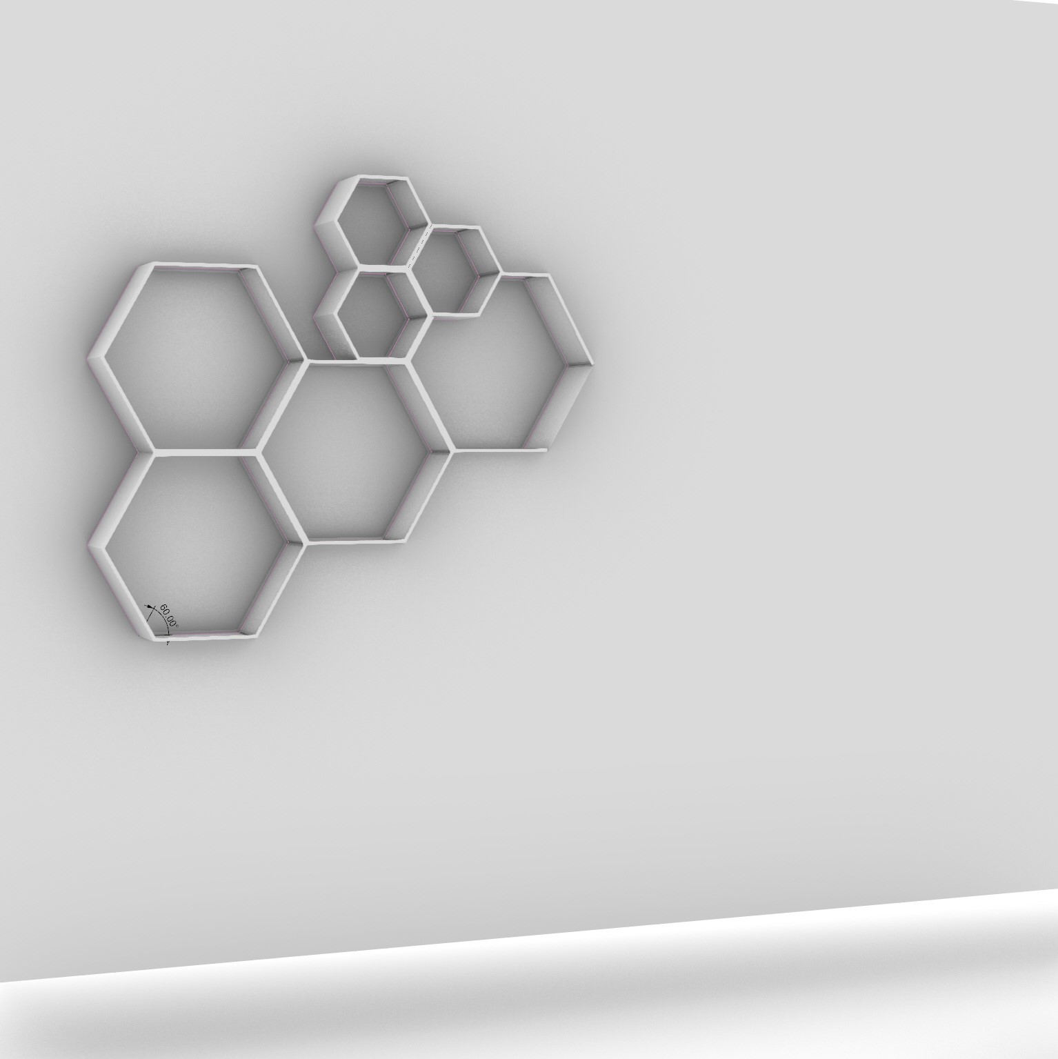
Designing The Unit:
I played around with hexagon sizes and some other shapes on Rhino and found a pattern I liked. When it was time to “UnrollSrf” (flatten
the surfaces to a planar surface) to arrange how the pieces would be cut on a sheet of OSB, I was wondering how to go about the beveled
cuts that I needed for my hexagon sides to meet. It turned out that the ShopBot machine couldn’t cut at a slope (only “2½D” not 3D) without
v-shaped bits – which we couldn’t locate.
I ended up making simple rectangle cuts for the dxf files and decided I could use an angled table saw later on to get the pieces to fit.
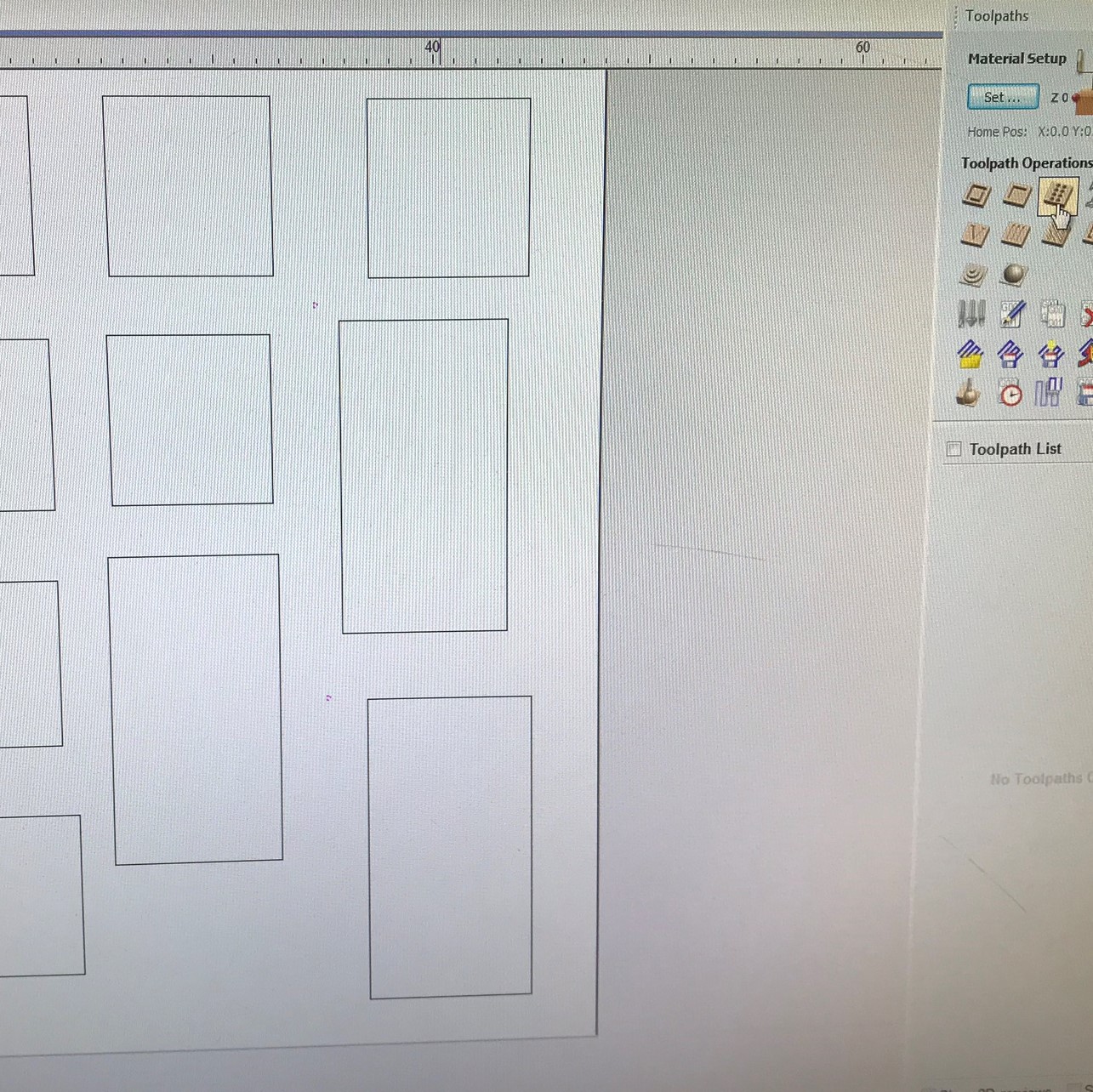
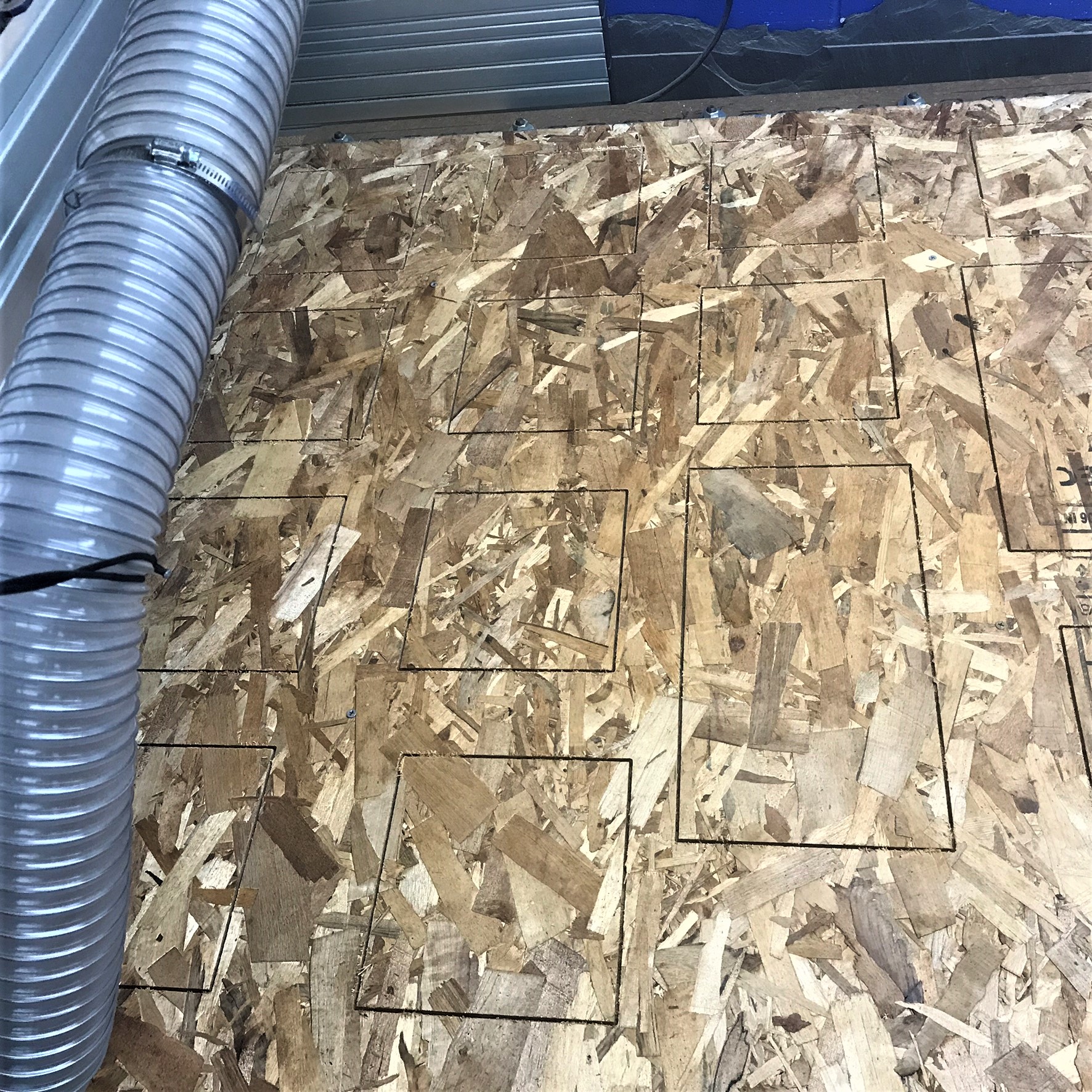
Cutting The Unit:
I uploaded the files and made all the cutting paths and drill hole paths (for the screws that keep the board down during the milling).
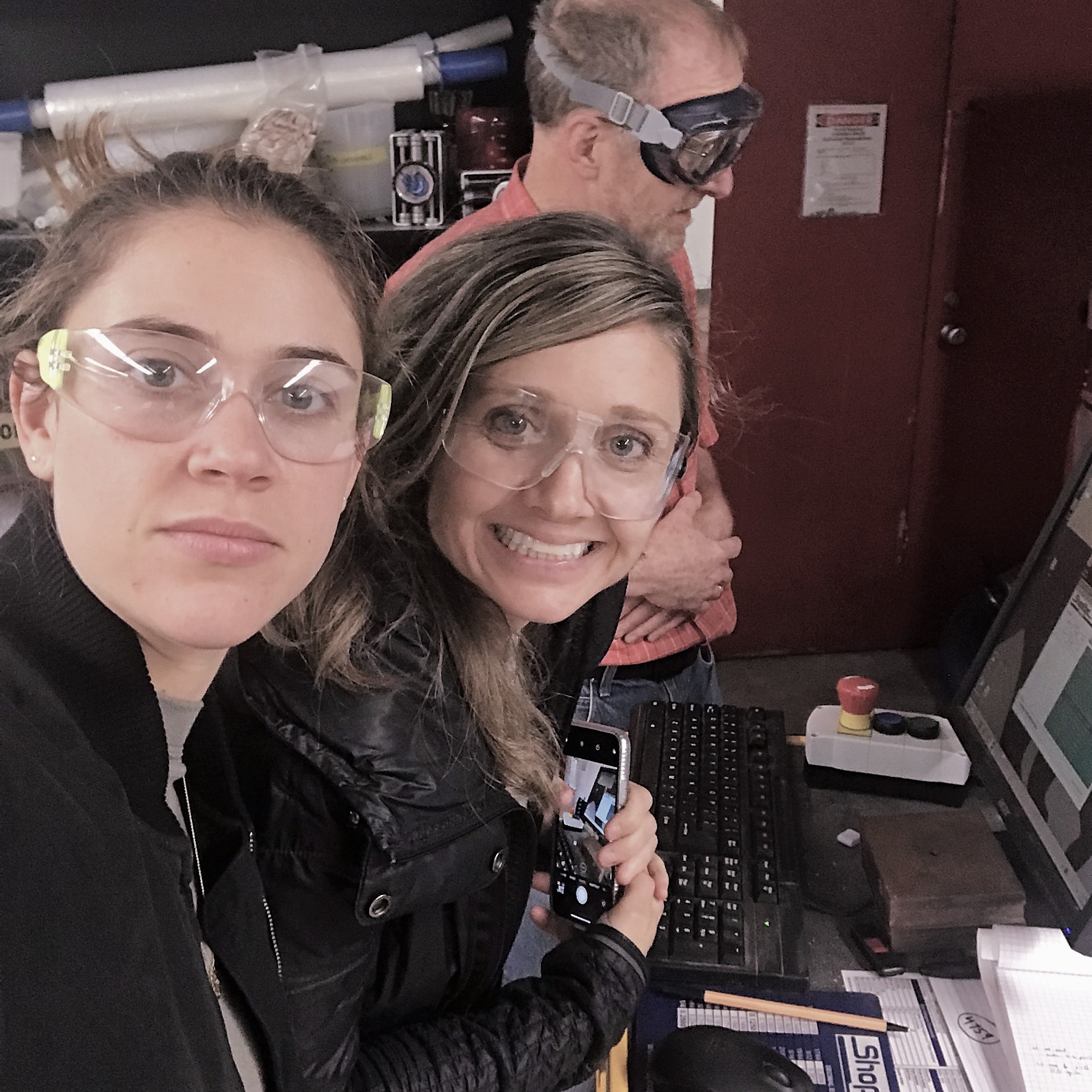
After screwing the boards down and running some tests on runout, alignment, speeds, feeds, and toolpath with Rob, I ran the cuts!
Everyone in the class's time slots got pushed and since a bunch of people were waiting for the machine (and Rob’s attention!), I was only able to cut
2 of the 3 4X4 sheets and was therefore missing 4 pieces (which I might mill next week). Luckily, since my design is modular, I conceded
to making it a bit smaller.
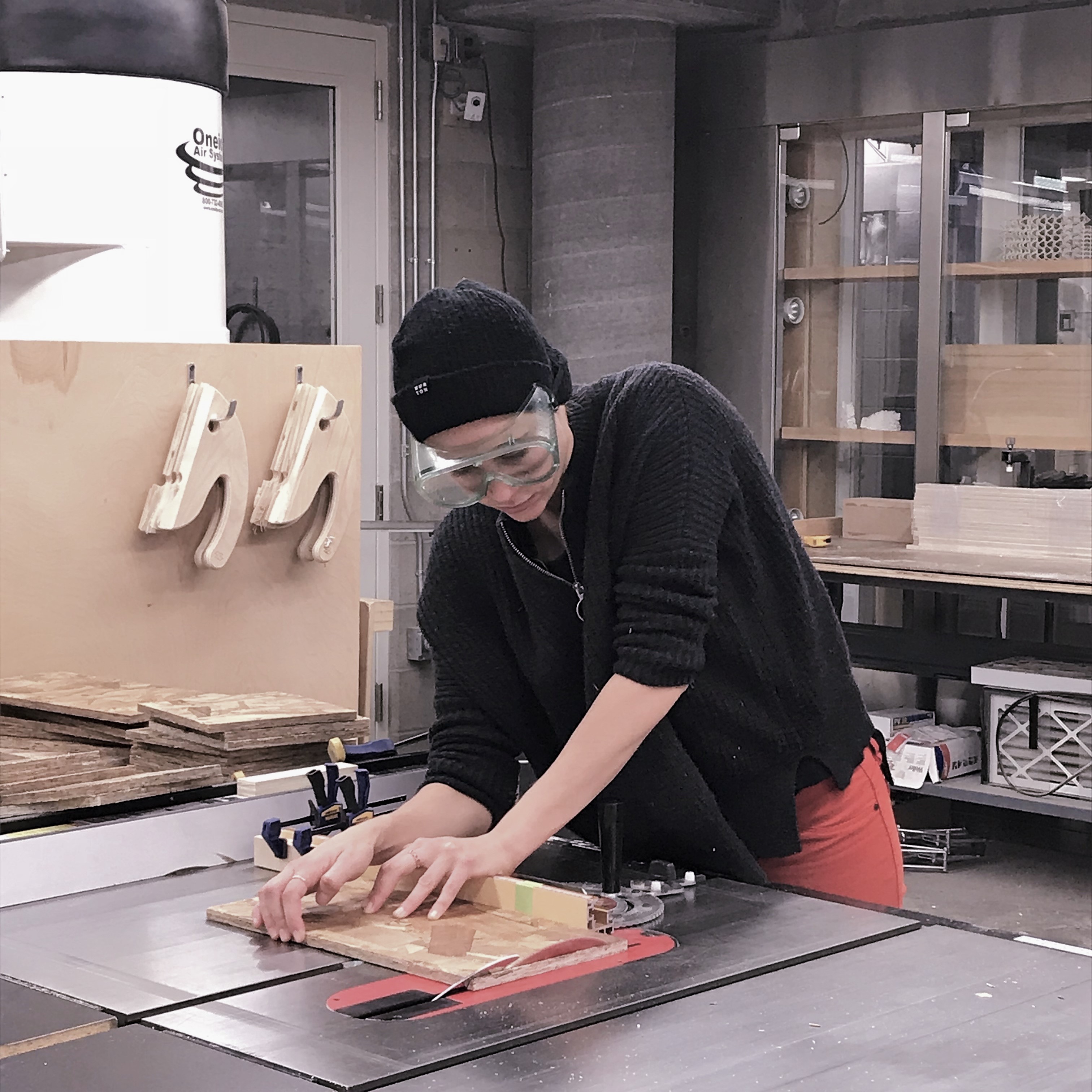
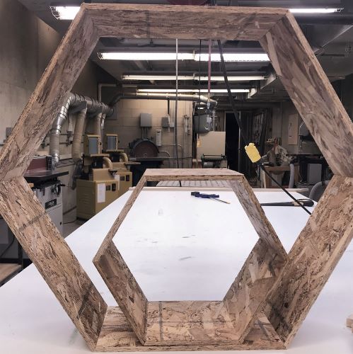
After cutting the pieces, I lugged them all to the GSD and used the table saw at an angle of 30 degrees for my 60 degree sloped bevels.
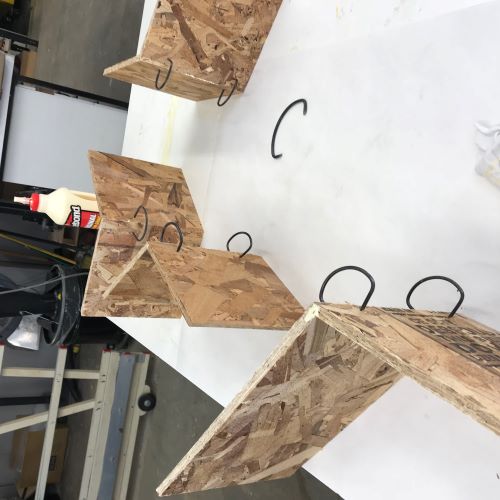
Constructing The Unit: As usual, I was pressed for time this week and was only able to constuct part of my piece. I constucted a large hexagon and a small one --
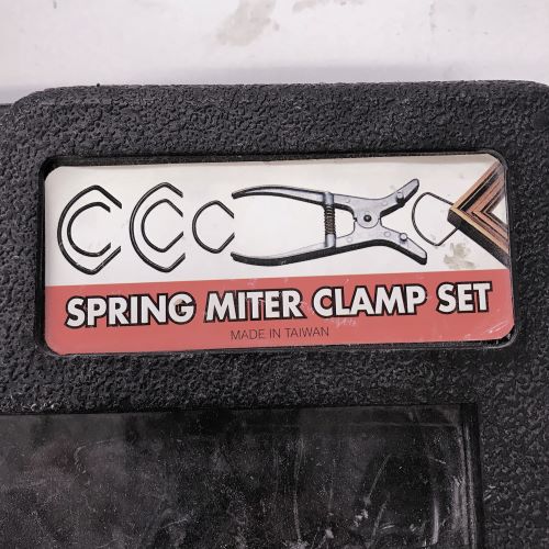
using wood glue and spring clamps to hold in place until it dried. The portions of the shelving unit that I completed came out really well - they look nice
and are quite sturdy. In order to hang them, and put any sort of weight on the shelf, I probably need to put a wood backing rather than being able to see through to the wall.
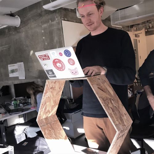
In the meantime, the units were used by my peers in studio as beautiful standing desks!
Embedded Programming
Make A Board Do Something
Reading a Data Sheet:
This week focused on embedded programming - the process by which we write code to control microcontrollers to do (almost) anything.
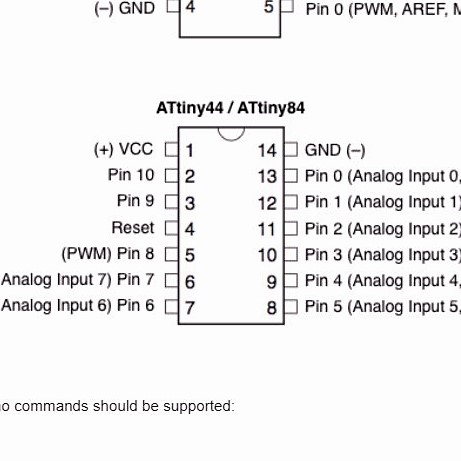
In order to begin to understand the capabilities of microcontrollers, we were tasked with "reading" the extremely extensive
Tiny44 data sheet. Most of the information in the document went over my head, but it was helpful for understanding acroynms, seeing example code, and
for the pinout which lists the part’s pins, their functions,
and where they’re physically located on the part for various packages the part might be available in. Most importantly, it shows how to determine
where pin 1 is/how the pins are numbered - critical for when pluggin the part into a circuit.
In relation to modern microcontrollers and microprocessors in our phones and computers, the ATtiny microcontroller is much
more simple (but it is still powerful for its size!). Since this microcontroller doesn't have much memory, Arduino with its libraries hidden under the hood has some consequences
when it some to the space it takes up/power recquirements -- a reason to use C code outside of the Arduino IDE. The overall goal this week, though, was to begin
to understand the capabilities of microcontrollers and get the general tool chain set up.
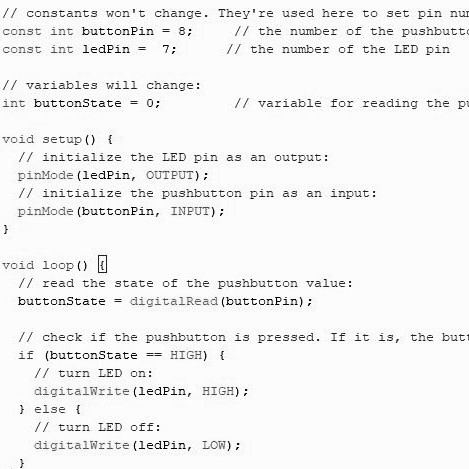
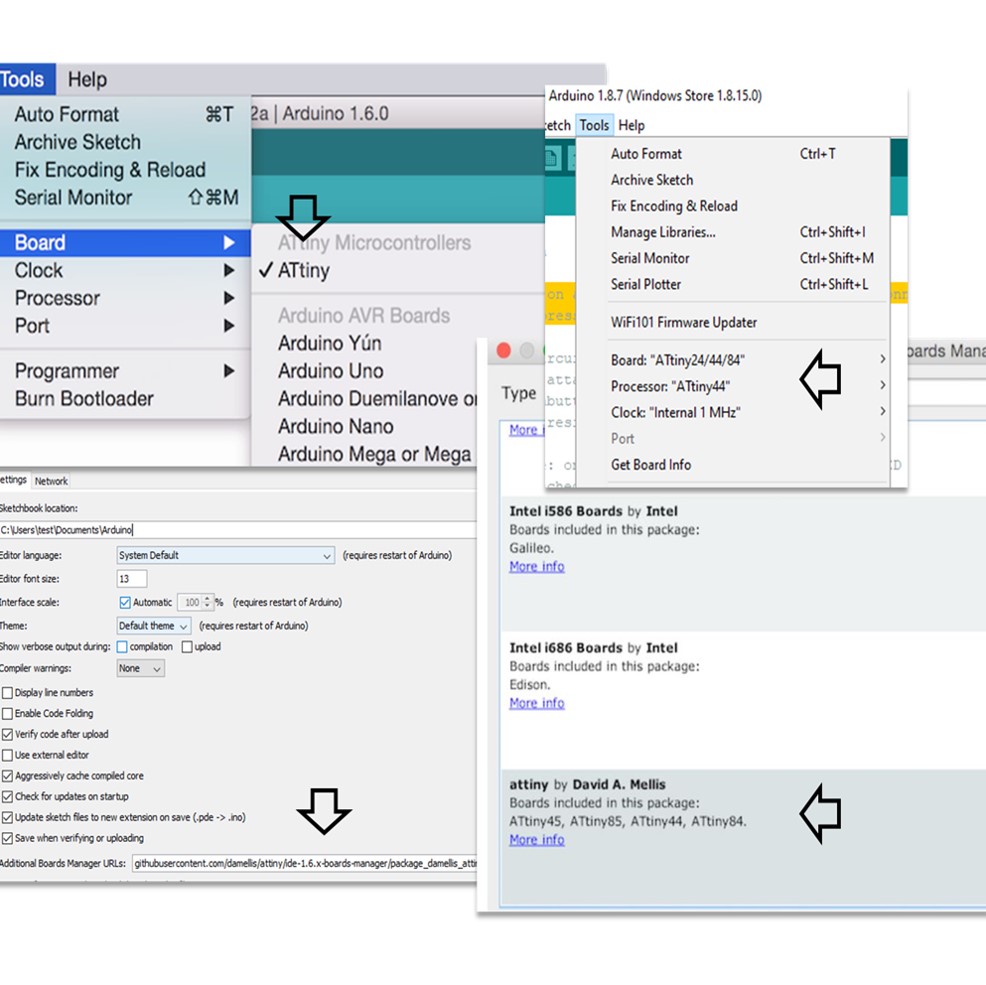
Loading Simple Arduino Code: I have very limited experience with programming so I started out in the Arduino IDE, with example
[File>Examples>Digital>Button] code to turn on and off an LED connected to a digital pin at the press of a button. I also had to add the
definition for ATtiny (not built into latest version of Arduino)– adding the ATtiny board in Board Manager and then making sure it is checked off as the board and processor.
All I had to do was make sure the pins in the code matched with where the pins on my board were connected to my LED and my button.
At first I didn't realize that Arduino has its own ATtiny Microcontroller Pin-Outs, but when I did, I changed the code to match.
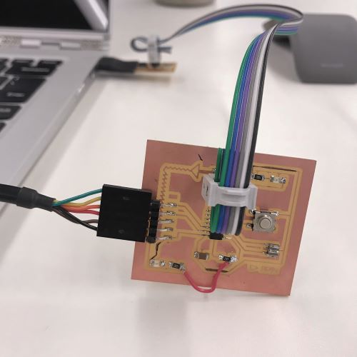
I plugged in programmer/USB to my computer, and the 5V FTDI cable to my microcontroller board and to power, making sure the the black wire was to GND and that it
was plugged with the components oriented the same way. My computer was not recognizing the programmer in Arduino or my PCB. I consulted Rob and the programmer was working on other computers
(I may not have had drivers installed on my comp?) but the clock on my board, we realized, was potentially shorted by some connected solder on top. I fixed the solder and
confirmed the connections with the multimeter, but unfortunately the board continued not to work on any of the computers around.
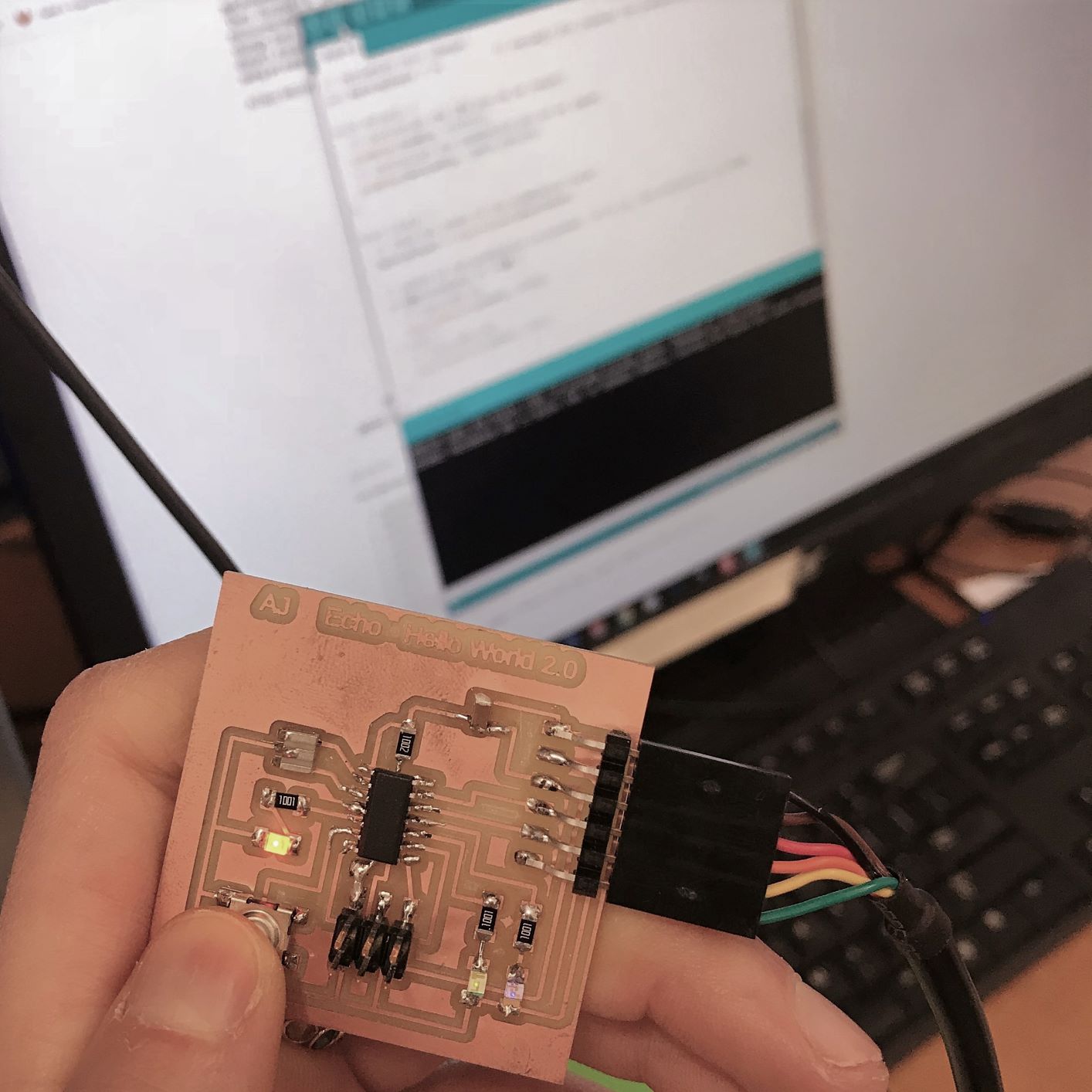
Luckily there was an extra working board laying around which I was able to load my code on and the button program worked with the correct pin configurations.
(Ben Yuan (TA) reccommends checking the following when there's a failure (rc=-1):
Programming cable is oriented correctly. (A Brian-pattern FabTiny will light up bright red if connected correctly, and dim red if connected incorrectly.)
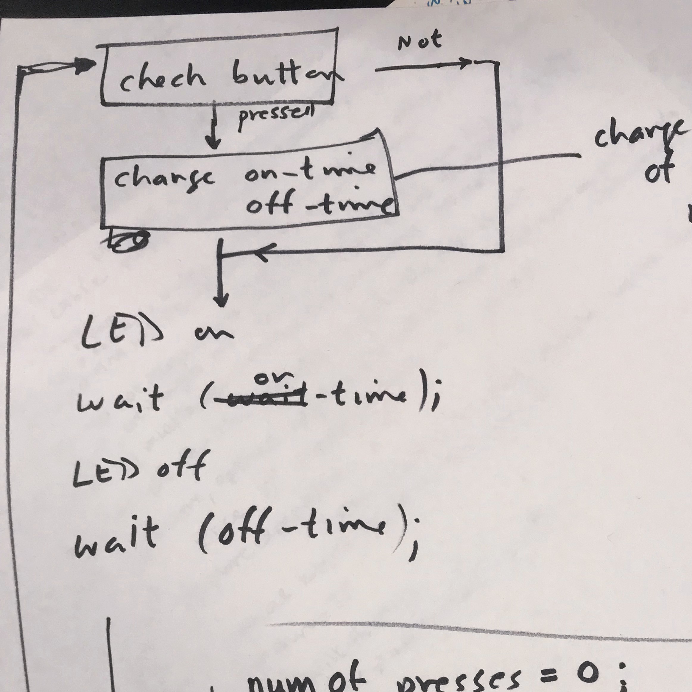
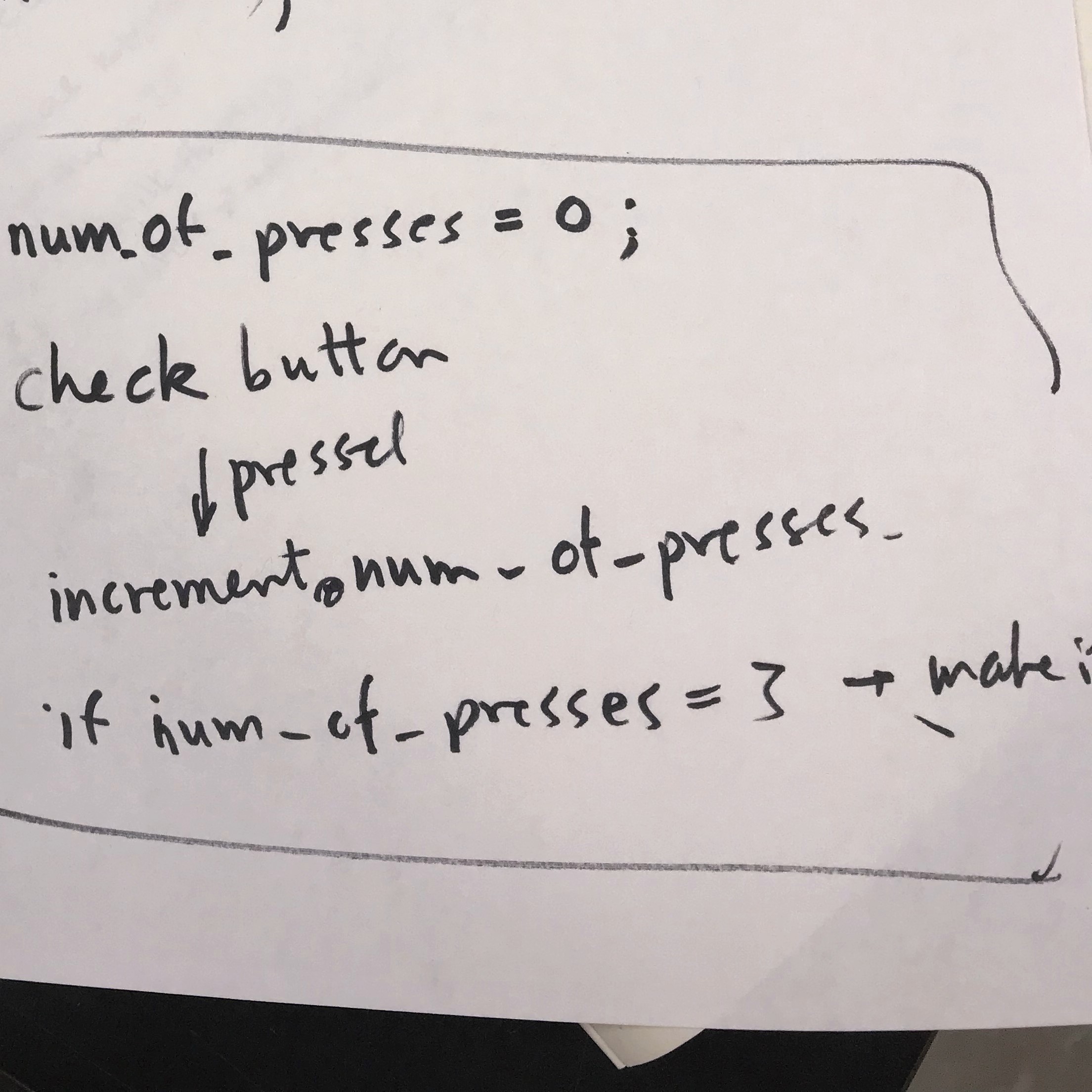
Playing Around With Code: I spoke with Rob about how to dim my LED progressively with button presses. I learned that
LEDs are not dimmed based on an increase or decrease of voltage (as is the case with incandescent lights.)
Light is either on or off, and the LED will maintain its operation at the same voltage and current level as if it were operating at full light output.
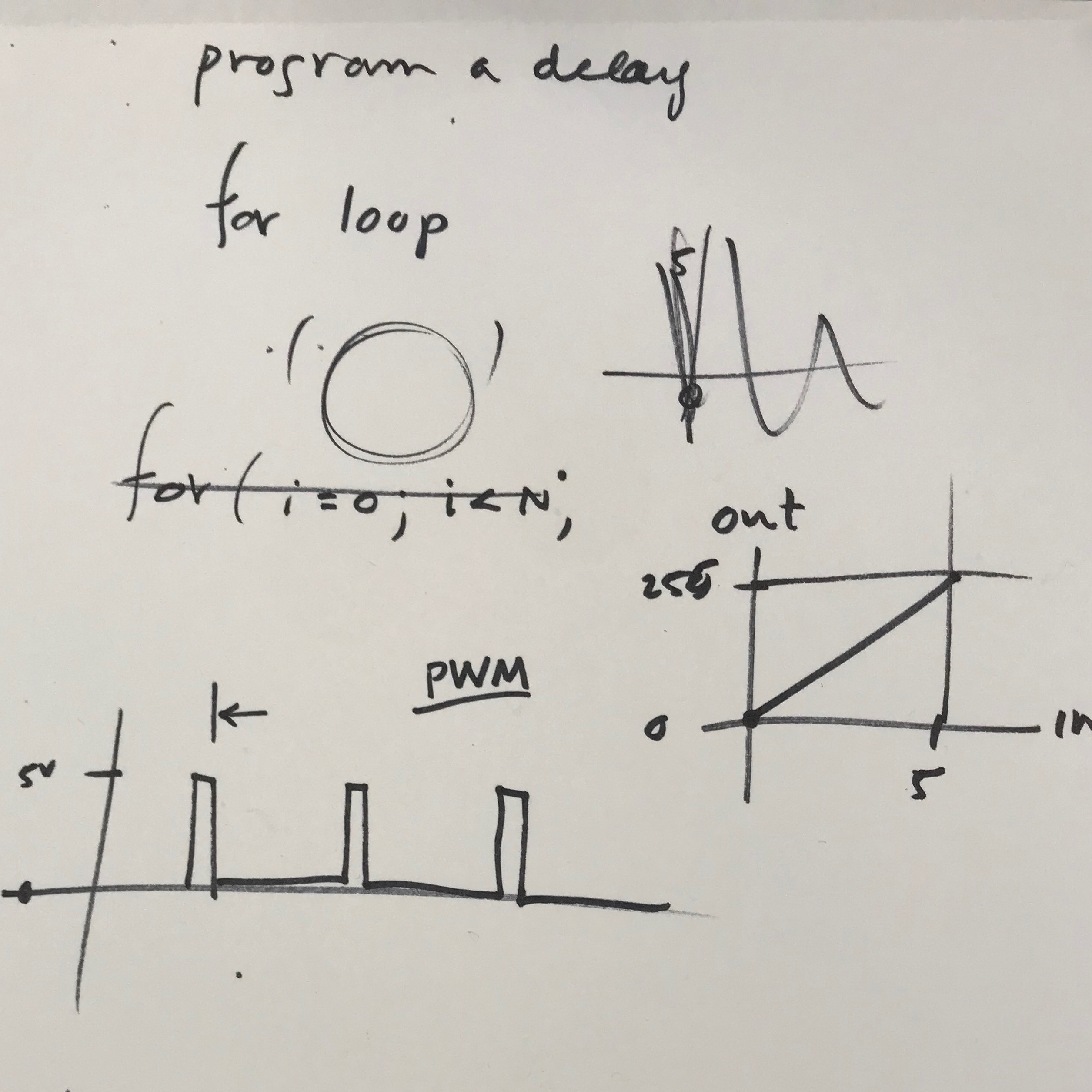
You can create a dimming effect, though, by essentially fooling the eye with pulse-width-modulation (PWM).
With PWM he LED is programmed to split its “on” time cycles, measured in milliseconds or thousands of a second,
into intervals where the light is “on” and “off.” The human eye takes the average amount of light out of the pulses; as long as the rate is high
enough, the eye won’t perceive any pulsing (tThe perceived brightness is linearly proportional to the PWM train’s duty cycle).
With Rob I mapped out how this would be done in code, and started to play around, but due to time contraints
didn't have the time to complete/load successful dimmer code.
Tools: PCB, Programmer board, Arduino IDE, 5V FTDI cable

Molding and Casting
"Design a Mold to Cast Parts"
This week’s group assignment was to review the safety data sheets for each of our molding and casting materials and practice pouring and making test molds.
As a group we also ventured over to MIT to watch a demonstration of sand casting aluminum. It was freezing cold, but worth it!
For the individual assignment, we were tasked with design a 3D mold around the stock and tooling that we'd be using, mill it, and use it to cast parts.
Designing the Positive Mold:
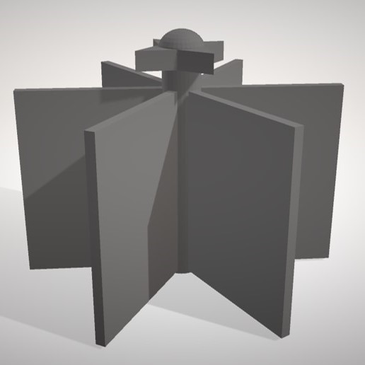
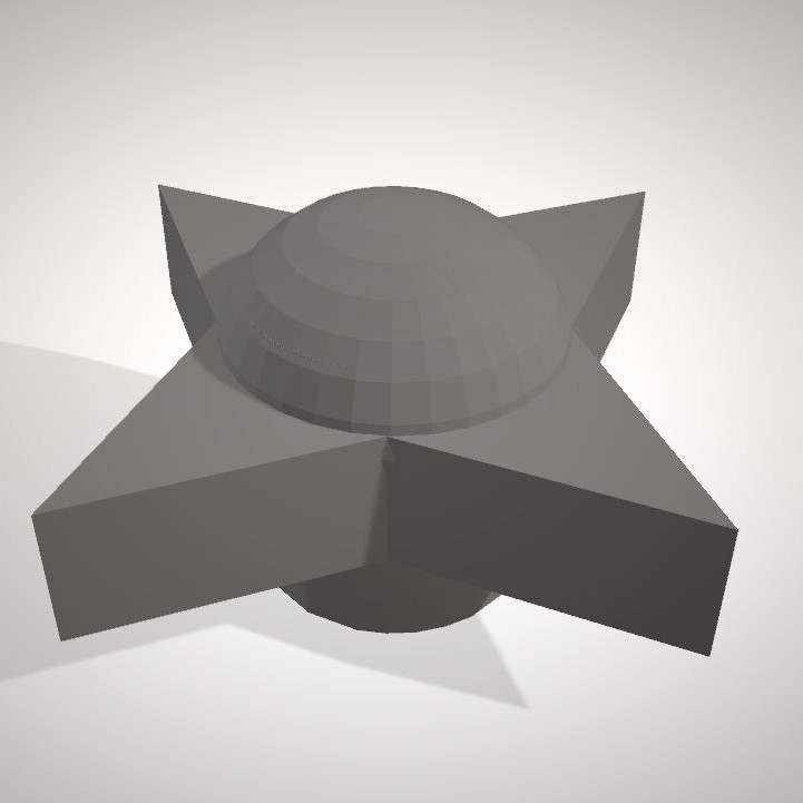
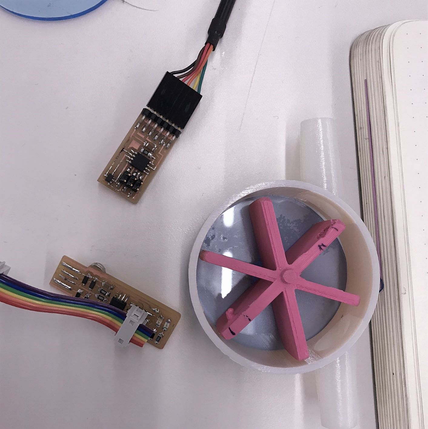
I went into this week intending to design the entire knob + rotating mill mechanism for a large gravity bin dispenser (the black parts in the picture below).
After modeling this as a connected piece, I was informed that it would be way too big and that casting was not the best method for making this whole
part - so I decided to just do the knob part.
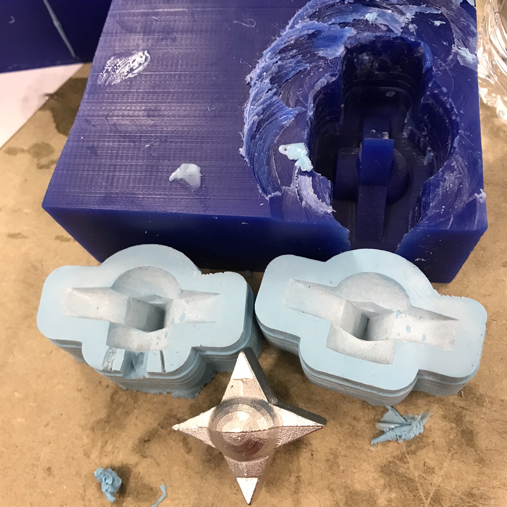
Since I wanted the knob to be the right size for a hand to handle it, but we were limited with the depth of the wax cube used for milling (3.5*3*1.5in) and the depth
that the shopbot bits could descend, I decided to mill half of the knob since it was symmetrical. I could then use it make a two identical part
silicone mold.
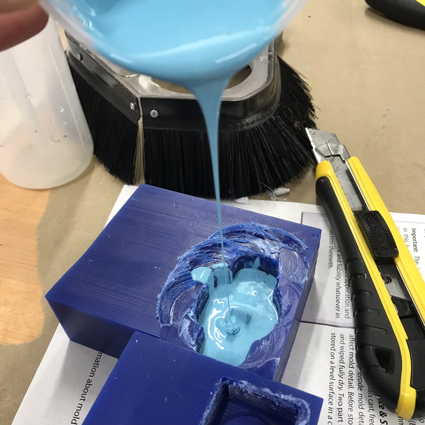
Making the Molds:
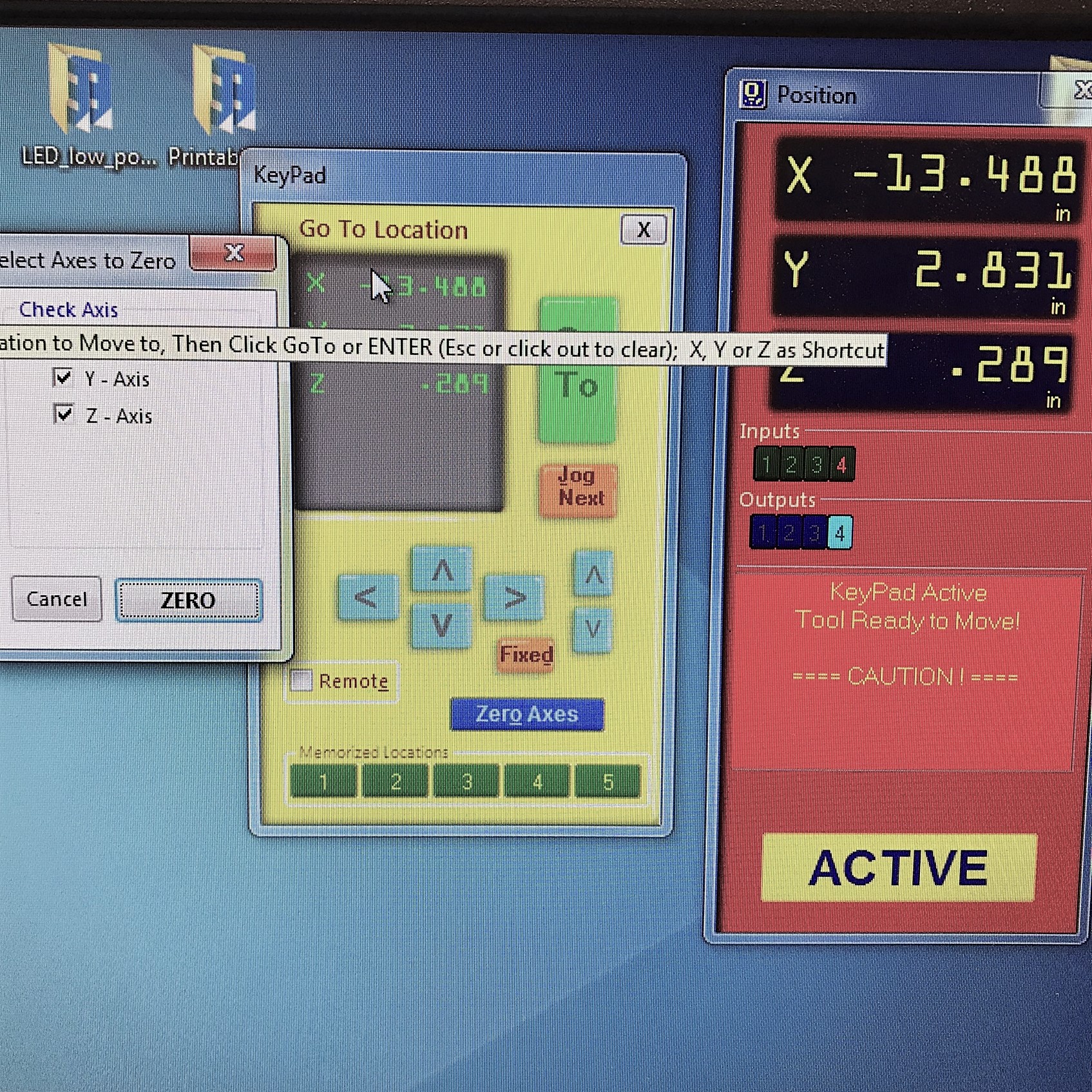
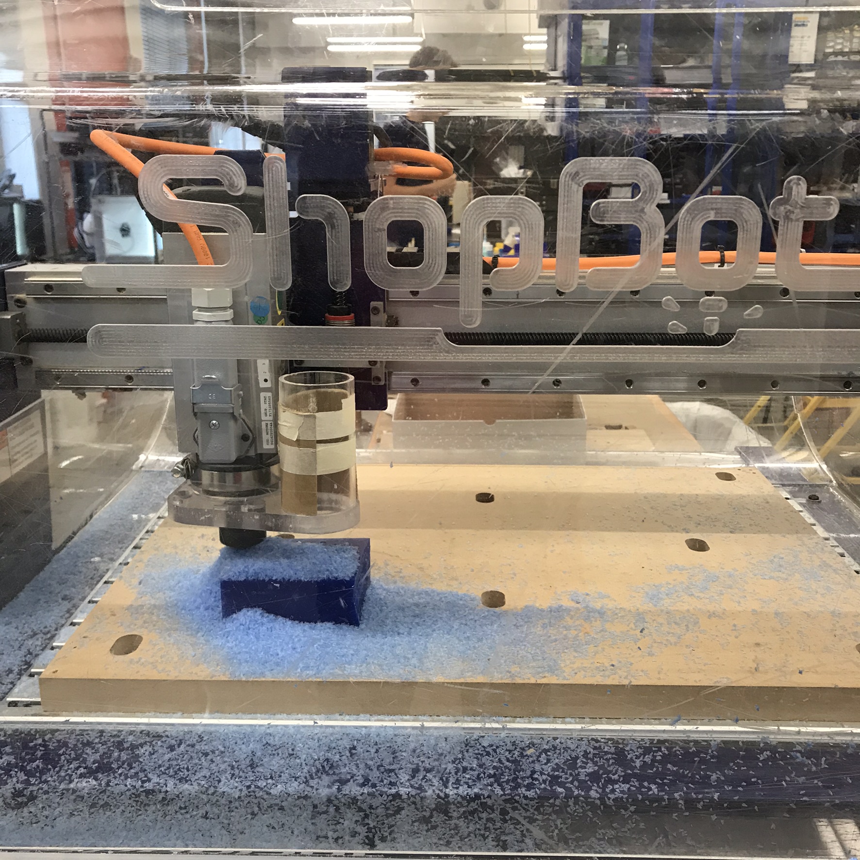
After a lot of frustrating adjustment, I was able to figure out and save the toolpaths for my initial rough cut and then my final cut for my design for the shopbot.
I uploaded the files, put in the right bits, taped down my block, zero'd the bit, and ran the rough cut then the finer cut. This made a successful positive mold. I then mixed my silicone, and poured
it in for my negative mold. It took 90 minutes to dry and I needed two!
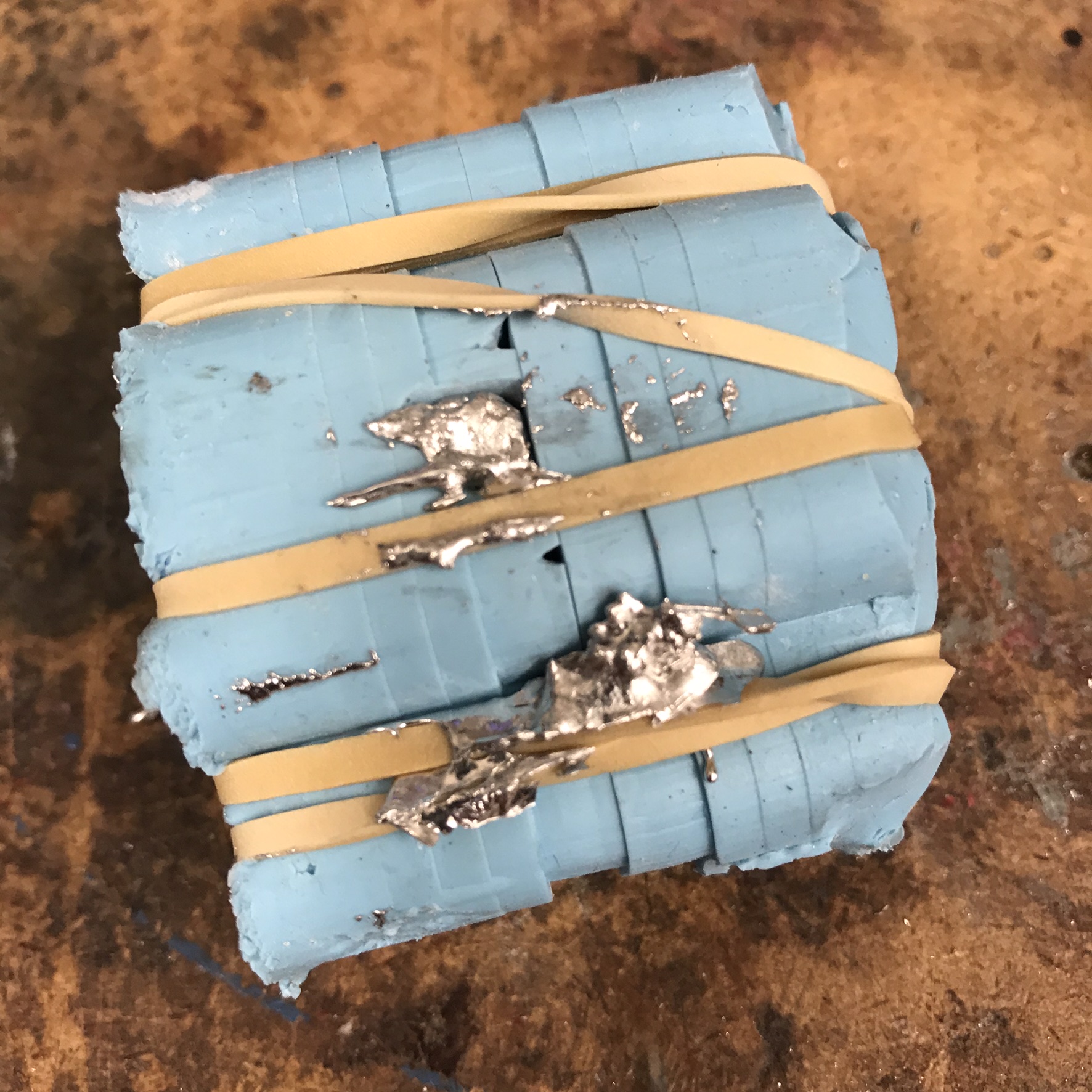
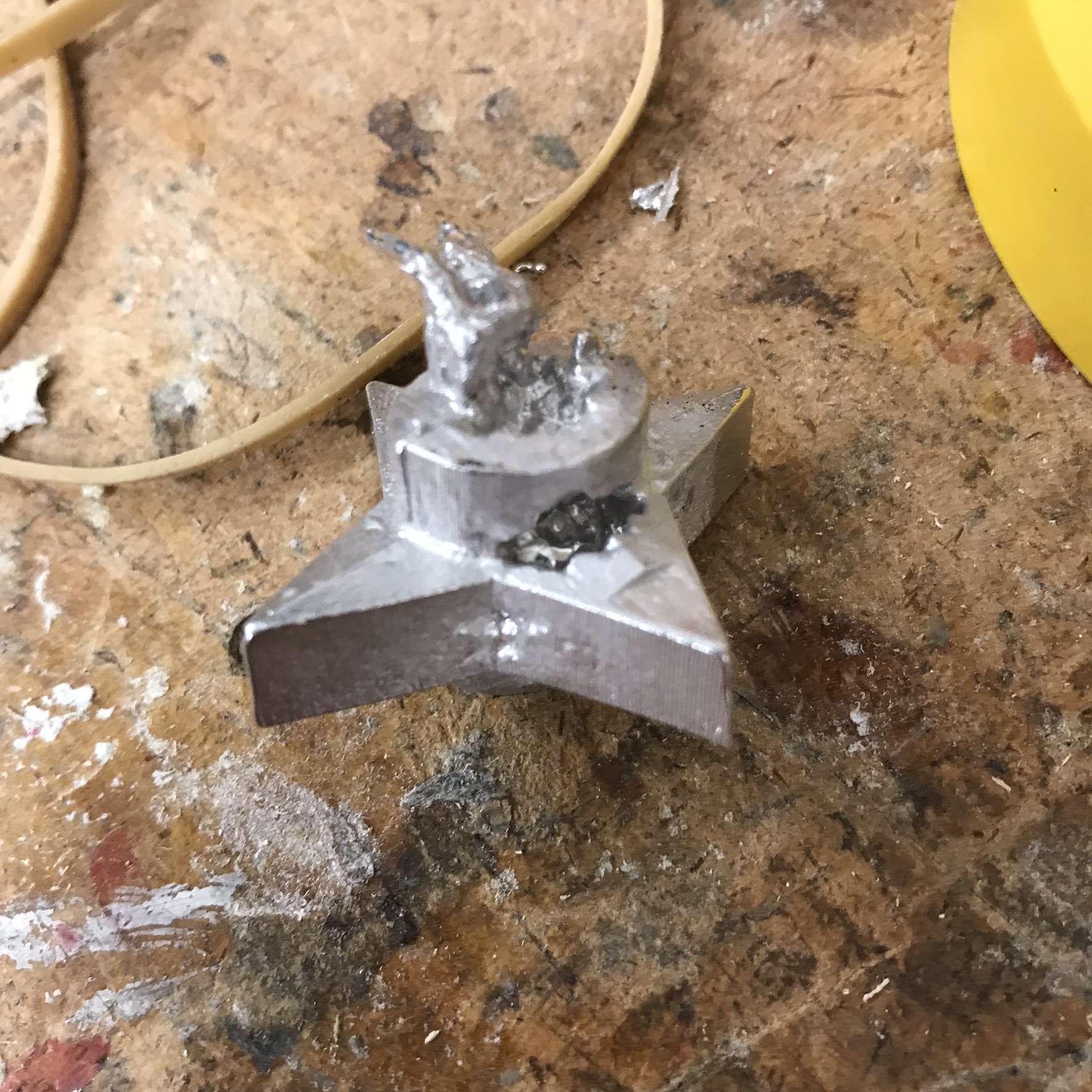
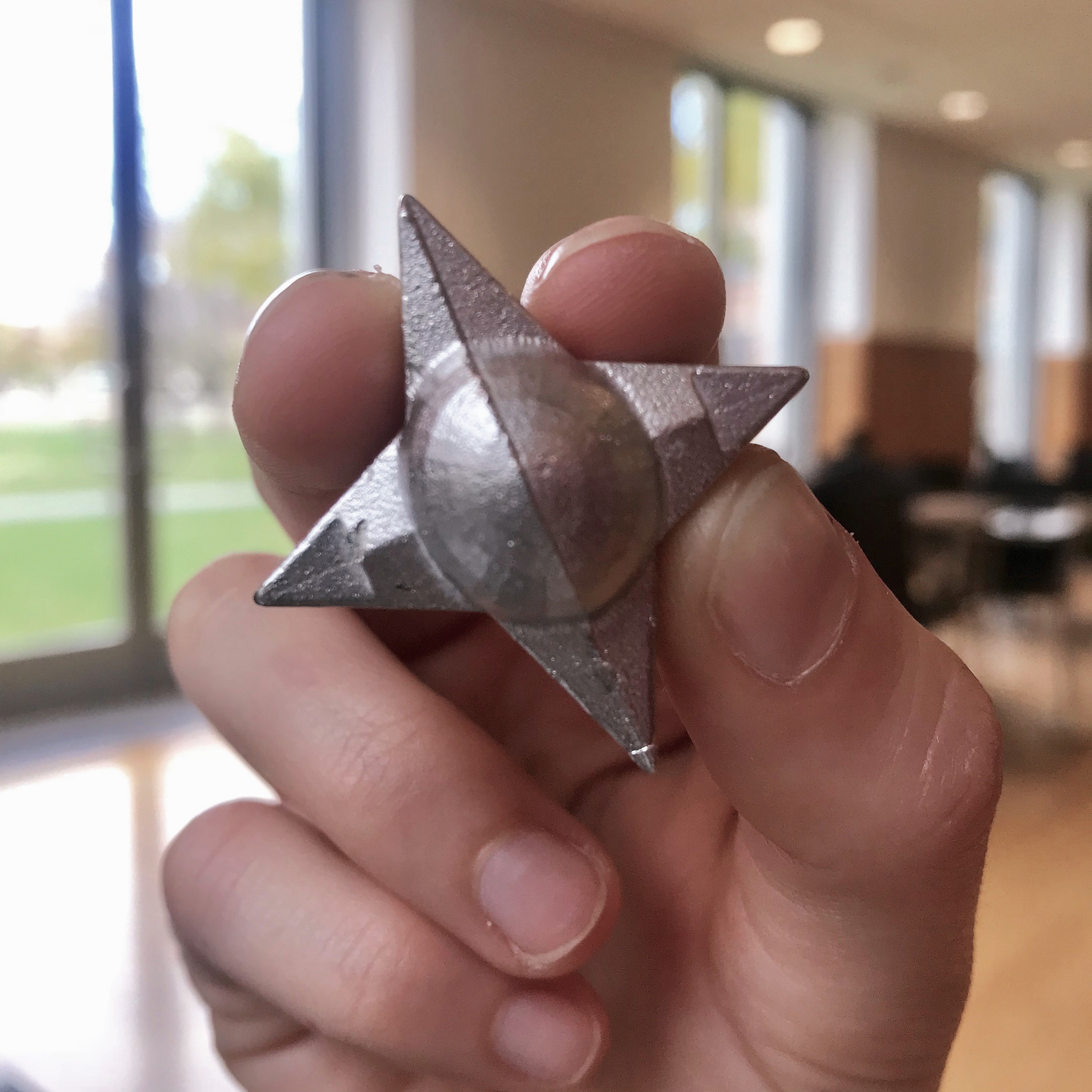
Casting!:
Once my silicone molds were dry and complete, I warmed up my metal in the toaster (450 degrees!), connected my two silicone molds with rubber bands, made a pouring hole
and an air hole, and then poured the metal in! The knobs were ready in just a couple minutes and looked great!

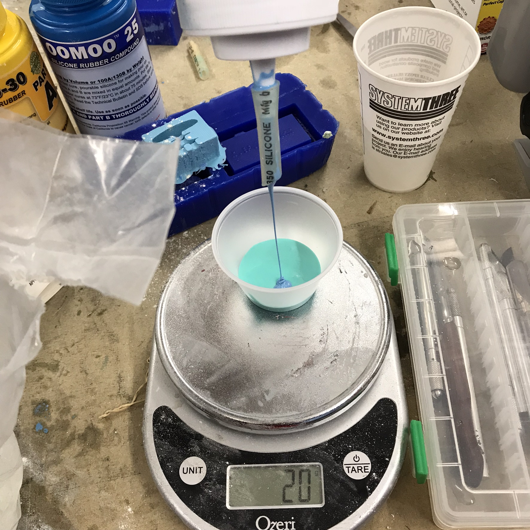
Tools: Rhino (I attempted to use Fusion360 but it was too much of a learning curve), desktop Shopbot, casting wax, Oomoo silicone rubber compound (combining 10 parts of A + 13 parts of B), certotrue (which is Tin + Bismuth)
Input Devices
Measure Something
Choosing Which Kind of Sensor to Build: The last couple weeks I've been thinking about the projects in terms of my final project, which
I'm currently thinking will be a dispenser for goods - similar to a vending machine but without prepackaged/preportioned amounts. So, critical
to my dispenser device is the ability to know how much was dispensed. I chose to make a rotary sensor to figure out how much has been dispensed (similar to
the way that a gumball machine works). There seemed to be multiple ways to sense how many time something had been rotated and even how much it was rotated from the "starting point".
My options seemed to include hall effect which uses magnets, light, or rotary based on capacitance.
Since there was a tutorial on the fab site which walked through
analog to digital (ADC) on the AVR tiny45, and the use of step response for capacitive-based sensors, I chose capacitive!
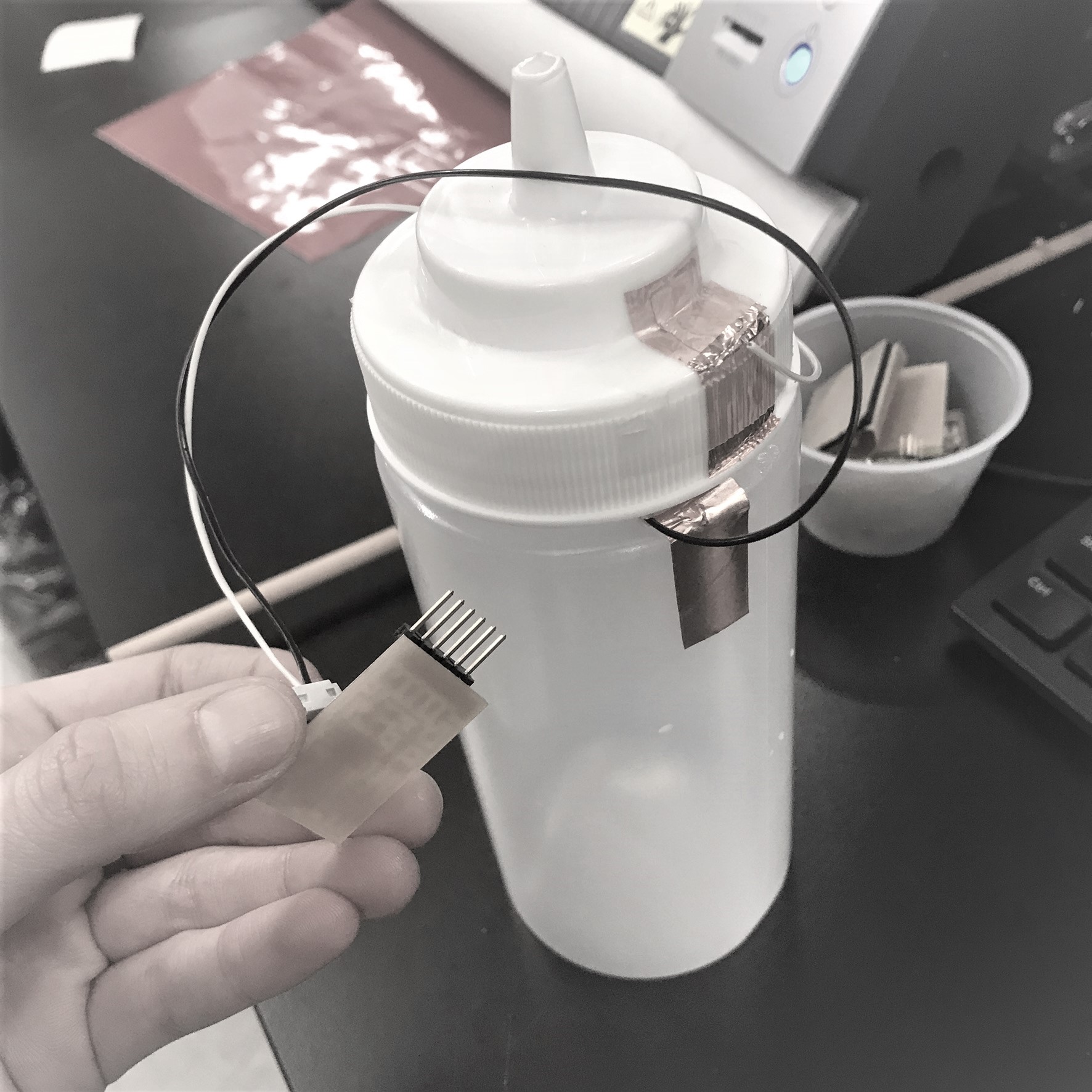
Add Sensor to a Microcontroller Board & Read It: I made a board using the design and schematic provided on the website under
step response, transmit-receive. I then used what I could find in the science
center fab lab that rotated (a screw top squirt bottle) to make a crude rotary sensor. At first I thought the copper strips had to touch one another upon rotation,
but then realized its just a electromagnetic feild and meauring the relative strength of that feild between the capacitive strips at a given point in order to measure rotation.
Figuring out the Arduino code wasn't too difficult since there were just a few things to be added to the code provided in the tutorial.
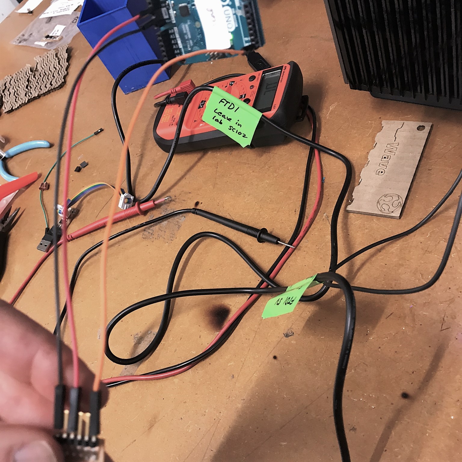

Running Into Issues:
When I tried to program my board, I first was missing the header file for the serial output, but then I was still not getting any output
from the serial interface in the Arduino IDE. After testing the board via oscilloscope and other means, I gave up and had to move onto other work. Right before class today,
Rob was kind enough to let me know that others found yesterday that the Serial communication problem is solved if you "burn bootloader" (under tools) so that the clock fuses
are set on the board. I plan to try this out tomorrow morning and make sure my sensor works!
Output Devices
LCD Display
After first learning what an output device was, I chose to design and program a board for an LCD output.
My final project does not really require any output device, but
I figured I would make an LCD display, to theoretically tell the user what they are dispensing and how much $ they owe.
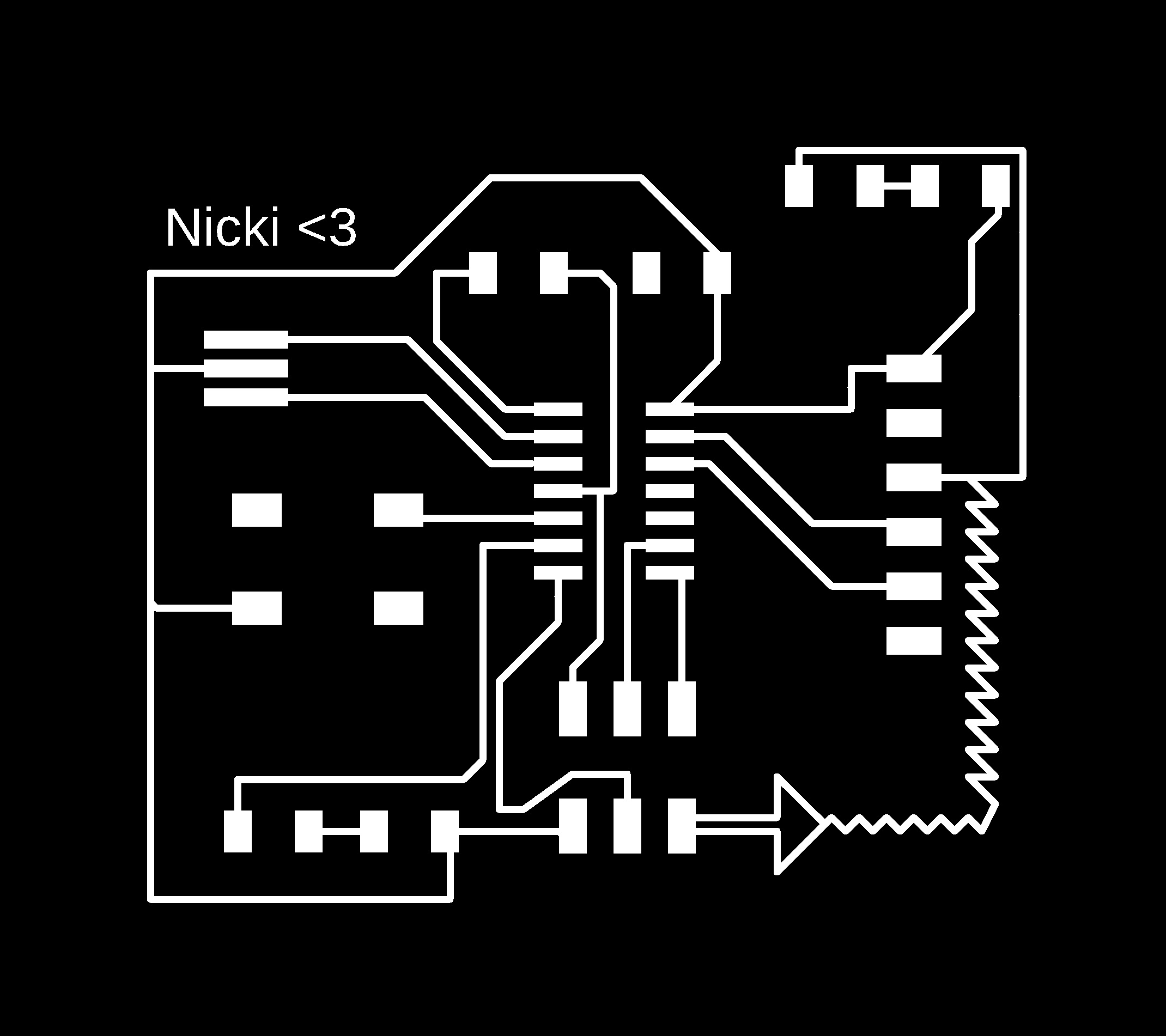
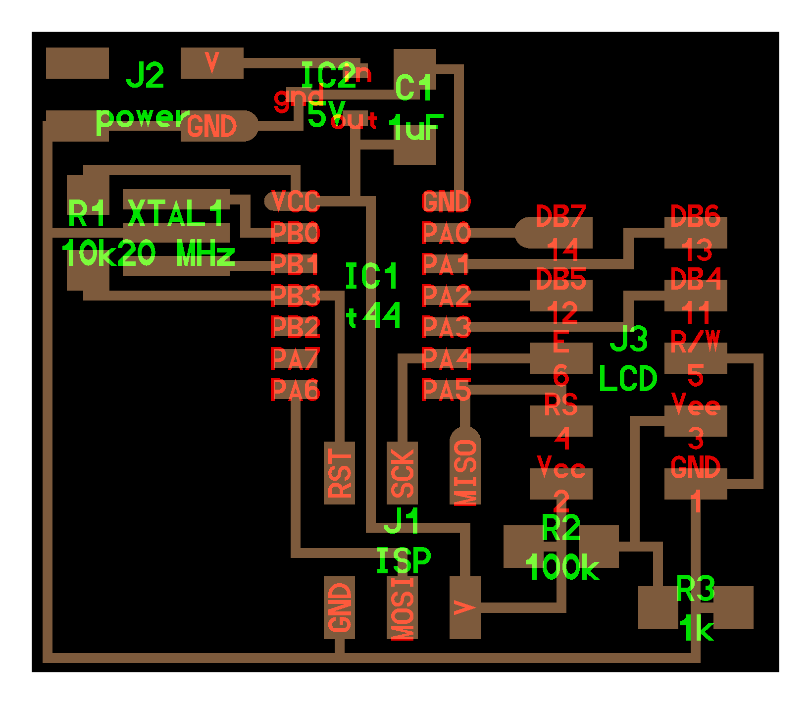
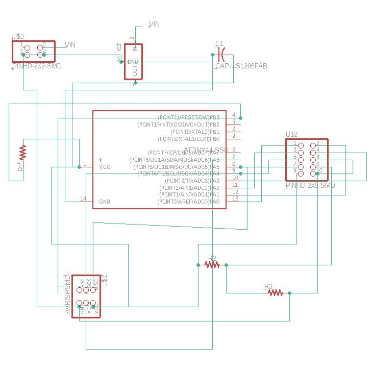
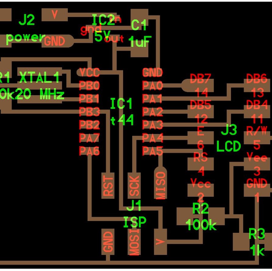
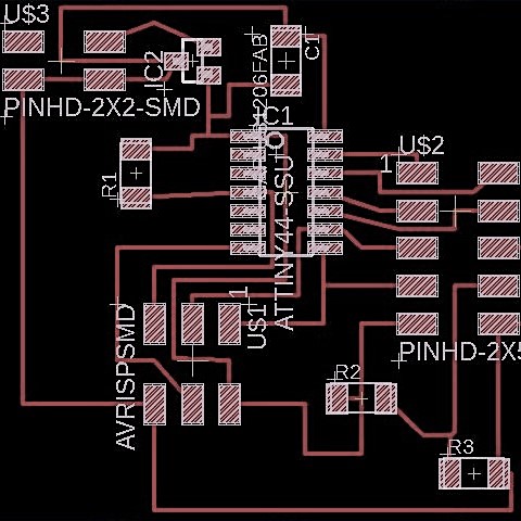
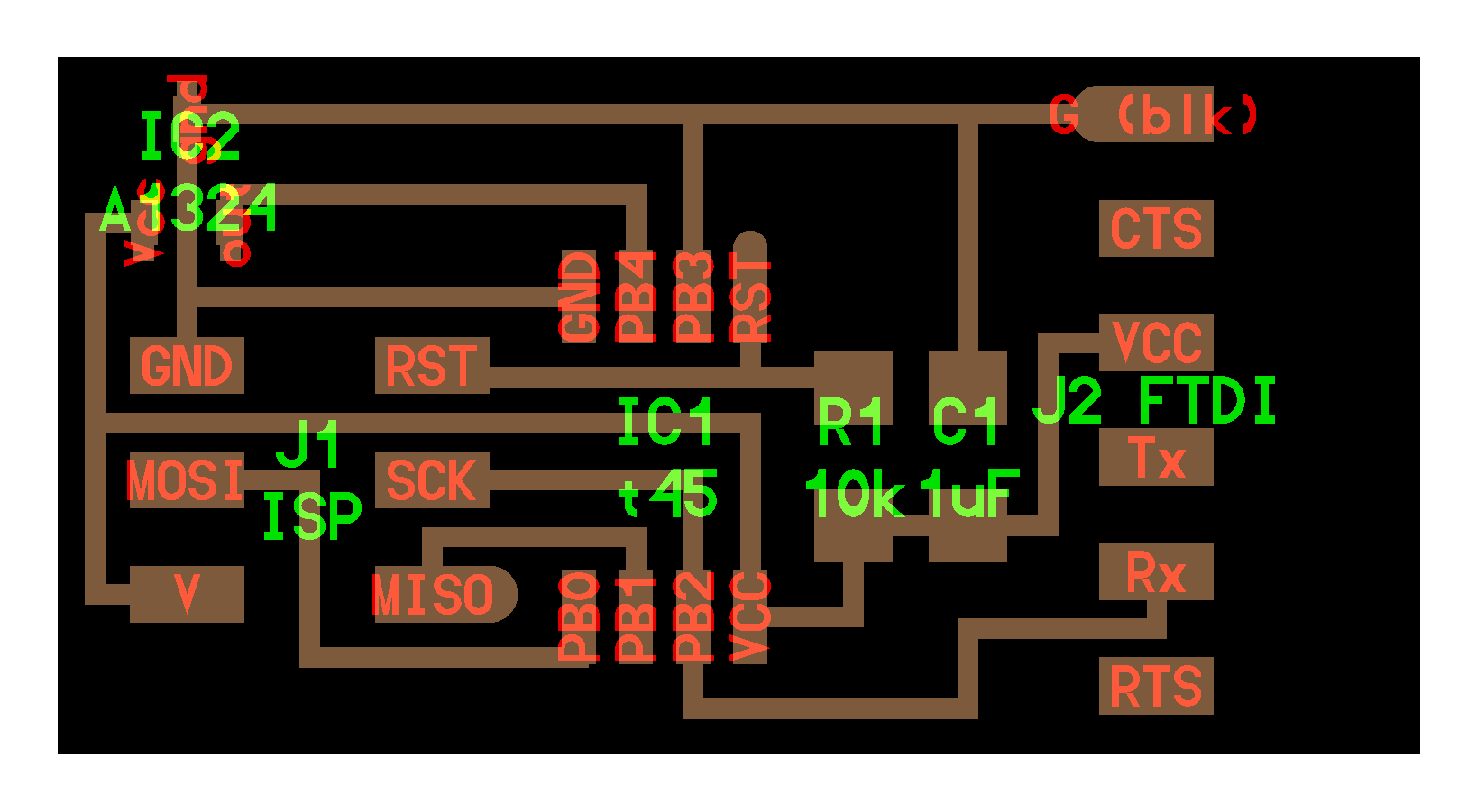
I designed a my board in Eagle based off of Neil’s LCD board.
I removed the clock. Below is the Eagle schematic and board.
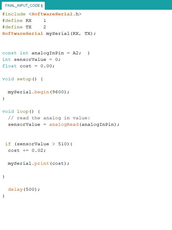
Software
I started with Neil's C code, but transitioned to using Arduino code. All I really
needed to change were the pin assignments (const int rs = 12, en = 11, d4 = 5, d5 = 4, d6 = 3, d7 = 2;) which needed to match my board and Arduino
ATTiny shematic.
Programming the Board
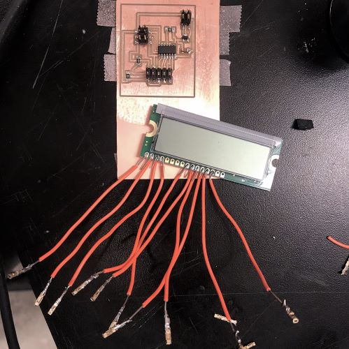
At first I continually got the rc=-1 error. First I removed and resoldered the regulator because it wasn't letting any power through for some reason.
Then I realized that something was going on under my ATtiny causing power and ground to be connected. I used the heat gun to remove that and resoldered.
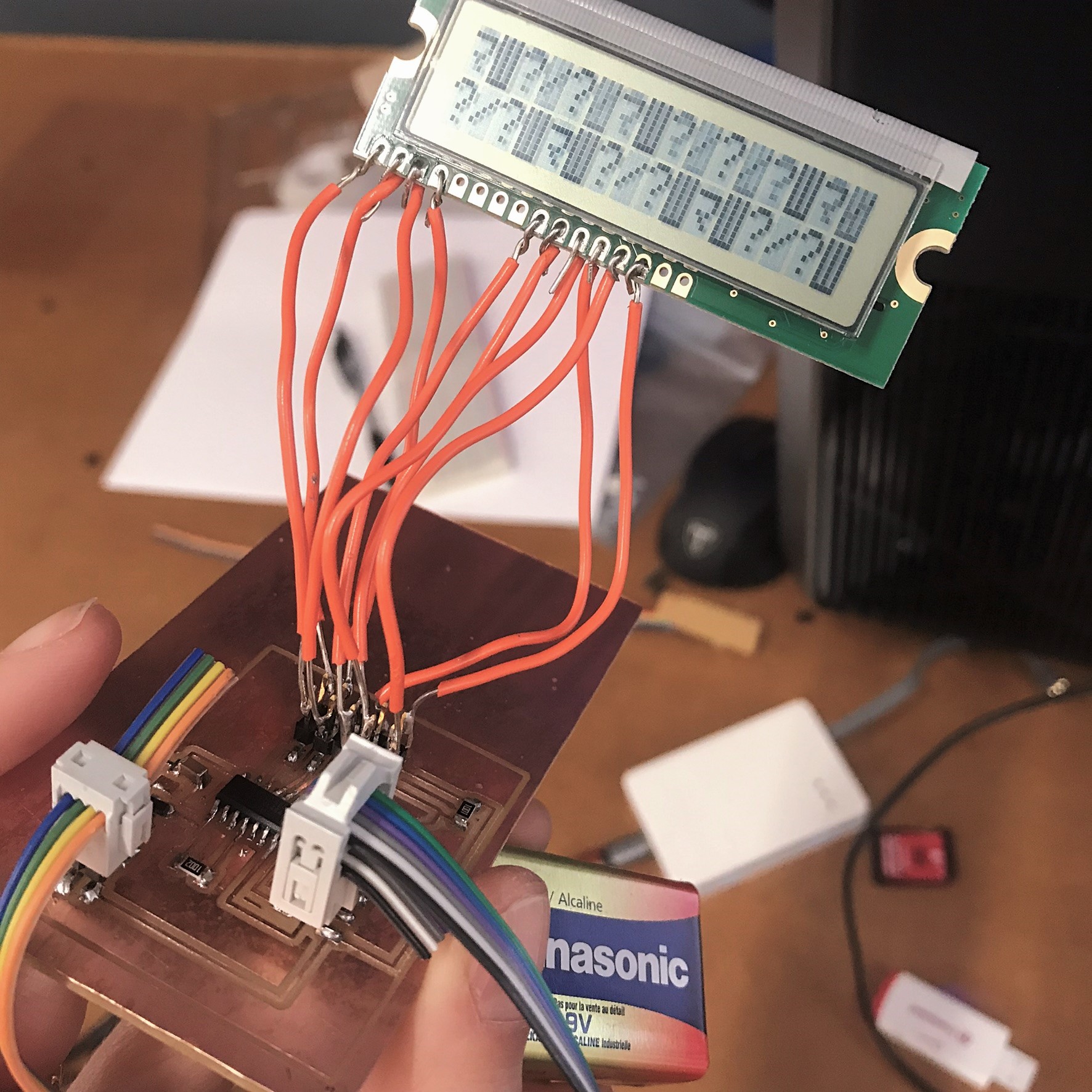
Eventually my board programmed, but unfortunately something was still wrong with the connection to the LCD because I was getting nonsense output (but at least I
was getting some output).
I plan to troubleshoot this further in later weeks because it would be great to use the LCD in my final (though not necessary!)
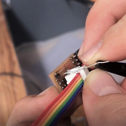
Update 11.28 - I resoldered the wires attached to the LCD and it started working!

Tools: Eagle software; Hitachi HD44780U dot-matrix liquid crystal display; copper-plated PVC board; electronic components
Machine Design
"Construct, Actuate & Automate A Machine"
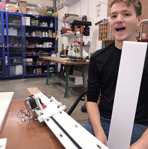
Building a tracked camera rig for creating smooth, panning videos.>
This week’s assignment was to design a machine (that includes mechanism, actuation, and automation), build the mechanical parts and
operate it manually, and document the group project and your individual contribution. For machine making week, our team’s goal is to create
a panorama/time-lapse camera rig, capable of sweeping 360-degree and cinematic linear motion. To accomplish this, we divided into the following groups:
Design (team:David, Sinan, Ryan, and Landon),
Firmware/Coding (Jeremy, Jackson, Soumya, Jeffrey, Abdul, Kenneth),
Electrical,
Camera Control,
Assembly (Me,Kate, Nicole, Hannah, Zaria),
Project Management & Documentation (Lins)
Documentation of the full process available on our amazing project managers site.
Design
The camera rig would have two axes: one for 360-degree rotation about the vertical axis, and one for linear translation along a track.
This would allow for tracking a subject as a central focal point, as well as panoramas.
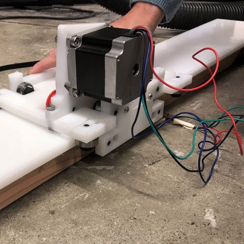
The plan was to attach a camera mount to the top of the stepper motor using a 14-20” thread and a coupler. The housing would attach to the motor
at the top with a recess for a lateral bearing to bear the weight of a DSLR camera.
While the initial press-fit design showed promise, the design team switched to a 3D printed housing which would drill to a base rather than requiring
press-fit connections, to allow the rotational axis design team and the linear axis design team to work more independently.
Plus, the smaller footprint would save space.
Originally, the design team planned to make the new platform bigger so that it could fit the double
width of the axis/rail ain order to mount the rotational motor/platform on top. After discussing it with the assembly team, and realizing that that would take a lot of extra time,
we decided to utilize the axis that was already made on Friday. Instead of rebuilding the entire sliding mechanism, the new plan was to drill holes in the current implementation
to add a small wooden offset platform for the camera mount to sit on. This way, we could use the piece we were currently printing and only re-make the track.
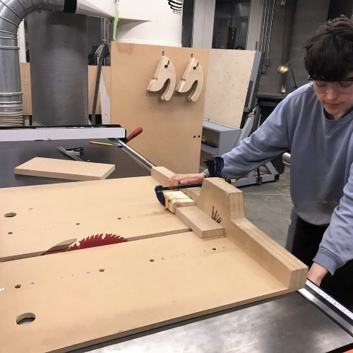
Assembly Part Two:
After the design meeting, we decided to make a longer track. We used the original rail as a guide to create the track mounting holes and cut a 2x4 as the base.
We had to find some wood screws long enough to get a good grip on the wood - luckily there were plenty. We found the center point of the 2x4 and HDPE rail, and
lined those up so that there would be enough clearance for the trolley bolts.
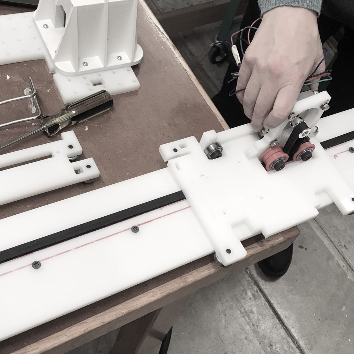
Assembly:
I worked with members of the design team to translate their vision into reality and with members of the assembly team who had already assembled an earlier version of the
track which needed some improvements. The The post-process work which was done by other members of the assembly team to prepare for assembly was relatively extensive.
After laser cutting the components in HDPE they had to cut them out from the board and use an exacto knife to trim off the excess material. For the individual holes they utilized
a drill press to clear out the individual channels on each of the components. The laser cut could have been slightly stronger, or slower, in order to ensure the pieces were fully
cut, to include the holes. After finishing the cuts, as well as the 3D components, an inventory of the supply box was completed.Organization of the components began by utilizing the
Assembly sketch. We started by assembling the ‘Preload stacks’, the ‘2x Belt Guide Stack’, the ‘12x Guide Stack’, as well as the hardware and belt components. Ensuring the stacks are
accurate is critical for the fit of the gantry to the rail.
Final assembly was hindered by a fit issue of the gantry to the primary track. The gantry was approximately 5mm too narrow for fitting the track. Prior to screwing in the
stacks to the HDPE the holes had to be punched for threads. This was simple, but proved difficult in that the HDPE was soft enough that too much stress when screwing the
stack into the board easily stripped the punched hole.
We had to ultimately replace the track, removing the belt ends and re-mounting them on new ends of a longer track. We had to make sure the new motor could be
mounted on the trolley on the track.
I unfortunately couldn't make it to class due to Thanksgiving holiday, but our machine worked:

Interface & Application Programming
"Write an Application Interfacing with Iput &/or Output Device"
I started this week pretty lost. I definitely learned a lot but havent quite finished this week's assignment yet.
I wasn't in the last class and it took me a bit of time to figure out what was required from this week's assignment.
I unfortunately didn't have a working input device or even my simple board with the button from a while back,
and I had just finally gotten my output device (an LCD) working, so I wanted to figure out what it meant for
an output device to connect with an application interface, and try to use my board.
Semi familiar with JavaSript, I started with a tutorial on using js with hardware, specifically an OLED
(I couldn't find one on LCD). It helped me undersstand how the javascript code talks to the Arduino and the OLED and how to make use of the "package manager" (or set of libraries?)
called Node.js. It xplained that serialport establishes the 2-way connection between the board and the laptop itself and
allows the laptop script to become the remote control for the hardware OLED screen.
If you go to the end of the video, there is a cool example of an application where you can draw on the computer screen with pixels and have that displayed externally on the
the OLED (pictured below). The video explains that it is helpful to use something called Johnny-five if you want to use javascript with hardware -
"Johnny-Five is the JavaScript Robotics & IoT Platform."
I then went on Johnny-five and found an LCD example. I was hoping it might work right out of the box and then my next step would
be to get it so you could input text on the command line to node and then it would put that on the LCD screen instead of the hard coded words.
Unfortunately, I ran into an issue right away. After downloading Node.js, and running npm install johnny-five in the terminal,
I tried to run node eg/lcd.js from the terminal command line and got an error. I couldn't find any fixes for this online. Additionally,
I was told by a classmate I ran into (this was late at night when no TAs were around) who said that since I was trying to use my output board (not the Arduino that this code used), I
might have trouble because it didn't have on it the 6-prong ftdi header that connects to usb to computer.
I decided to spend the rest of my time this for this assignment on watching tutorials on Processing (which Rob informed me might be the easiest to learn from scratch)
and to, instead of using a board, create fake serial data and adjust the data and have it produce an interface in Processing. This is just to make sure I understand how the application
interface might communical through serial with input/output devices. I've been interested in learning about Processing as I've heard it
is really relevant to design and visual arts. Processing is an open source language/ development tool for writing programs in other computers. Useful when you want those other computers to
"talk" with an Arduino, for instance to display or save some data collected by the Arduino.
Networking & Communication
Make Wired &/or Wireless Network with Addresses Connecting Multiple Processors
Since I this week is crazy with finals and I don’t actually need networking for my final project, I didn’t want to spend hours making and milling more boards.
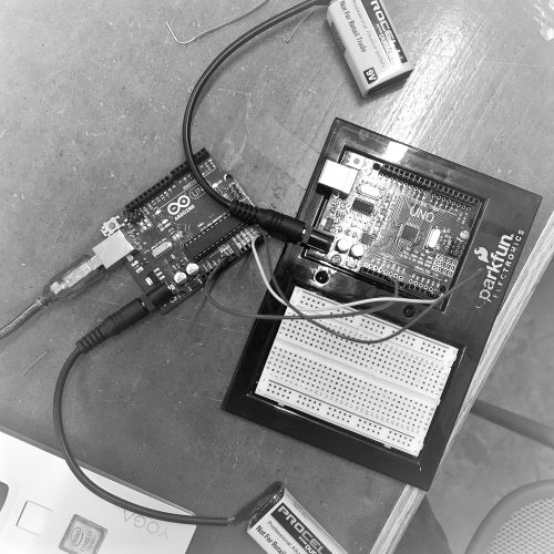
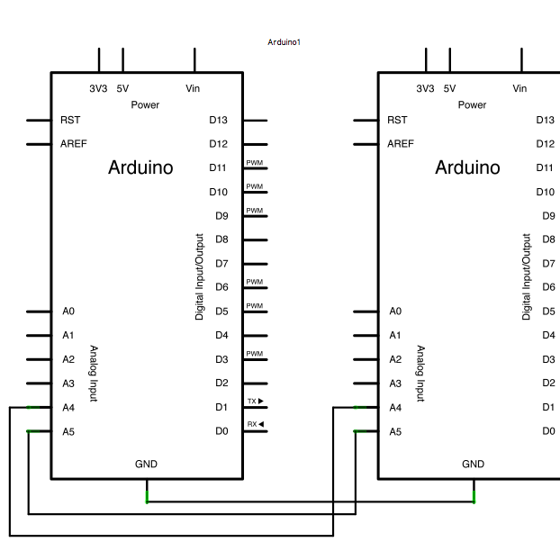
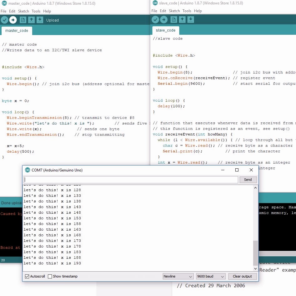
Instead I decided to use Arduino boards and program them to communicate with one another in a Master Writer/Slave Receiver configuration via the I2C synchronous serial protocol.
The Master Arduino was programmed to send a certain amount of data every half second to a uniquely addressed Slave. Once that message was received, it could be viewed in the
Slave board's serial monitor window opened in my IDE (the slave was connected via USB to my computer)
This was a bit of a cheap way to fulfill the assignment, since the sketch was readily available online and the circuit was
extremely simple to set up… But still think the set up and associated background reading taught me about communication and networking.
The I2C protocol - a synchronous serial computer bus - uses two lines to send and receive data: a serial clock pin (SCL) that the Arduino pulses at a regular interval, and
a serial data pin (SDA) over which data is sent between the two devices. When this information is sent - bit after bit -, the called upon device executes the request (and
transmits data back, if required, over the same line). Each Slave device has to have its own unique address; it would be possible for the Arduino boards to communicate
with many other boards using just two pins of the microcontroller, using each device's unique address.
In general, I learned in order for individual circuits to swap their information, they must share a common communication protocol, categorized as parallel or serial.
Serial communication is the process of sending data one bit at a time, sequentially, over a communication channel or computer bus. Parallel is where several bits are
sent as a whole, on a link with several parallel channel. Serial (e.g. keyboard and mouse cables and ports) is so common because it helps save input/output pin;
parallel is fast, straightforward, but requires many more input/output (I/O) lines.
I also researched how Bluetooth or Wi-Fi or some other network might serve useful for my final project. My final is linked to a larger project where I want to
A) be able to charge residents of a building for how much cleaning liquids they dispense and B) communicate remotely to “home base” when the liquid level is low
and needs a resupply. The flow meter that I’m making is tracking the exact amount dispensed, but I was trying to figure out the best method of enabling the payment.
The tricky parts are that I wanted to avoid cash, and even having to use a card, if possible, and have it all happen on a phone, and there needs to be something
to initiate the transaction identifying who the user is, but then the system has to wait until the dispensing has happened, in order to know what to charge.
I landed on the possibility of using QR codes - the QR code is not holding information about how much is dispensed, but rather who the user is. When the user
scans their QR code, it triggers the start of a new transaction, so the machine can then communicate how much was dispensed. I’d have to have them sign up
with an account on a "app" (webpage probably) that can then show their QR code to the dispenser. I also found
this hack
hack where you can add a magnetic card reader that allows any card with a magnetic stripe –
a library card, credit card, or school ID – to serve as a unique identifier. This card reader is connected to a Raspberry Pi which handles all the registration and eventual
payment processing via Venmo.
Tools: Arduino Unos
Wildcard!
Machine Knitting
This week, was a really fun wildcard week where we were all given the opportunity to pursue one of a myriad of production options.
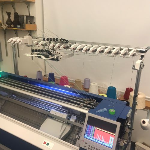
Having done a research project on applications of 3D knitting during a summer internship, I jumped on the opportunity to try out the Shima Seiki .
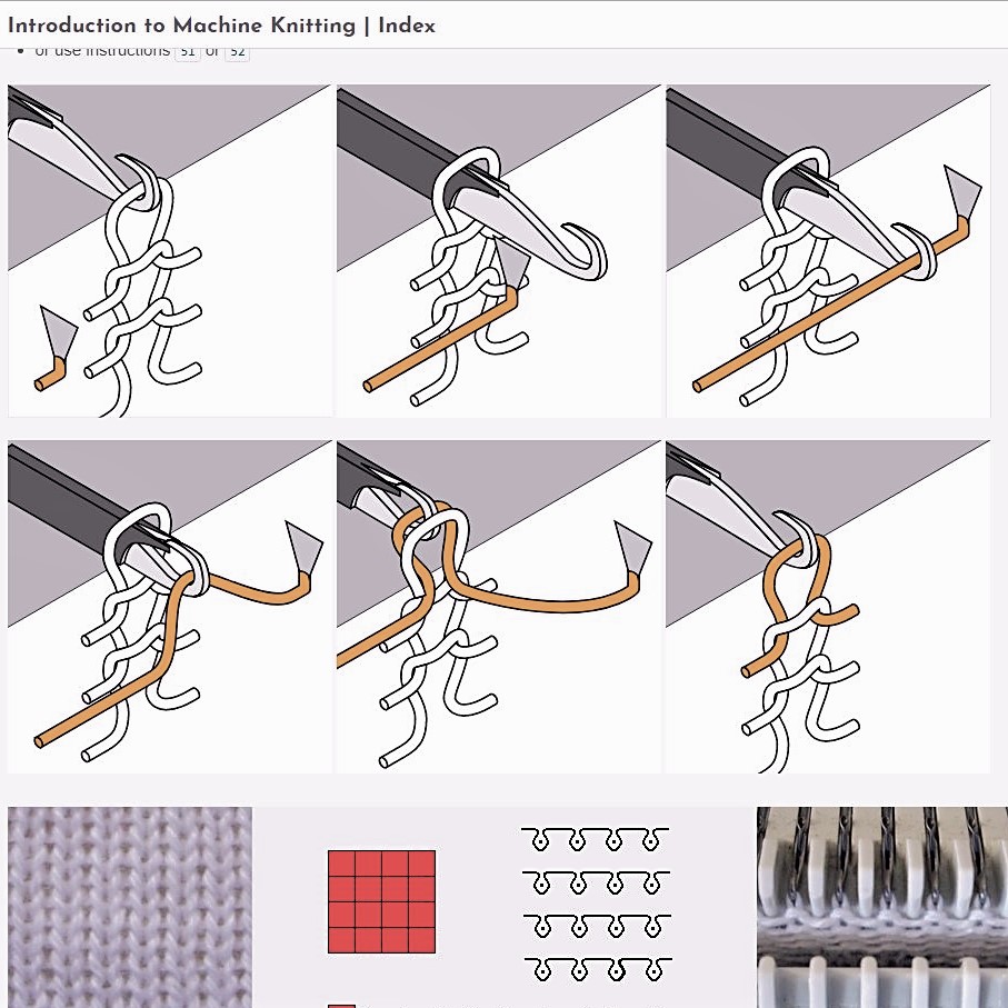
We had a few hour introductory session by Alexandre Kaspar to begin to understand how machine knittng works and to see the WHOLEGARMENT machine in action.
All the material that was presented to us about knitting vs weaving, how to introduce different stitches, when to use various stitches, and how the code is translated by the machine,
is available here (it is a really helpful guide that I'd highly recommend checking out!).
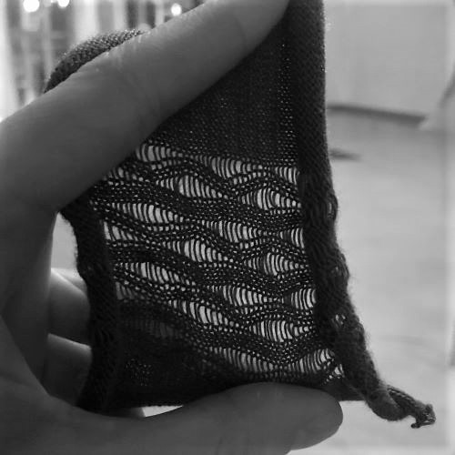
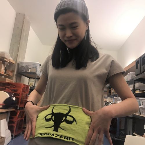
We then each had scheduled sessions to knit our own item. Unfortunately I was the last scheduled session and a needle broke a couple sessions before me, so there was a major delay and some rushing to get everyone in to
make something. The most popular option was two-sided "Jacquard" knit fabrics where we were just supposed to design an indexed PNG and send
it to the proprietary software through the lab computer. These came out really beautiful. I was there for Rae's (Biovazard picture below) and wanted to try something else, so I
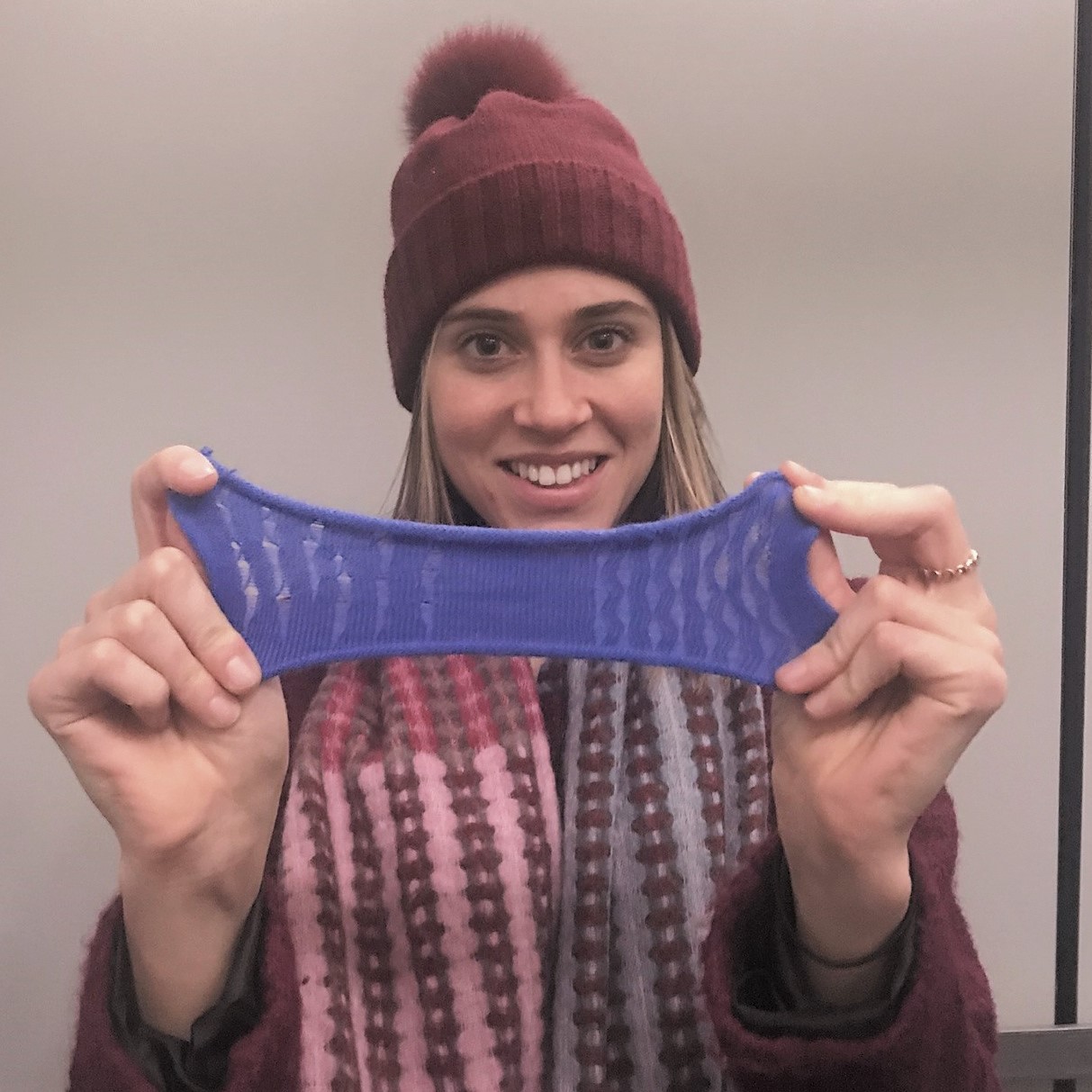
chose to insert a few different stitches from the stitches library.
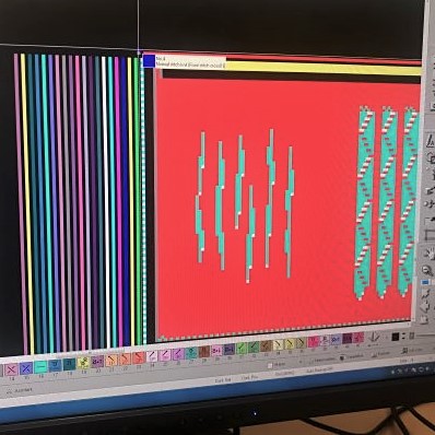
Unfortunately since there is such a steep learning curve to understand the various stitches - when you would use which, how to program them, and then how to understand them
within the visual color coding language - so we were encouraged to do something more out of the box. It was still cool to understand how to program the needle movements which
produce many of our garments!
Tools: Shima Seiki WholeGarment SWG091N2; 15 gauge needles; acrylic yarn
Final Project
Flow Meter + Display for Dilution Control Device
Towards the end of the semester of H2MAA was also when I began to narrow in on my idea for my Design Engineering capstone project. For the capstone project,
I am interested in looking at shifting the paradigm of delivery of and access to household necessities to reduce environmental footprint and social & financial costs.
What I have decided to focus on to start, is building a dilution control device for dispensing cleaning products with a physical and system redesign oriented toward usability
and affordability for consumers.
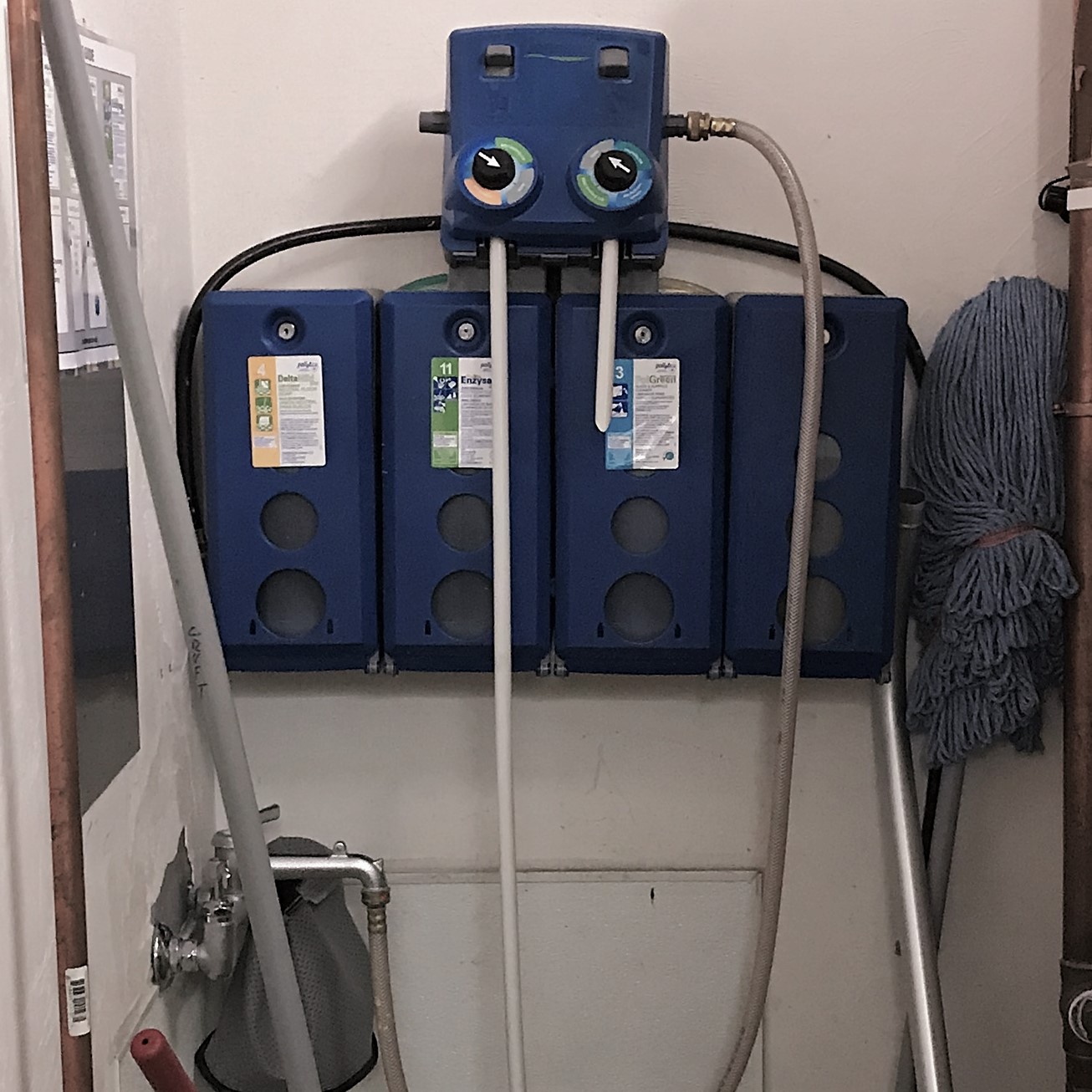
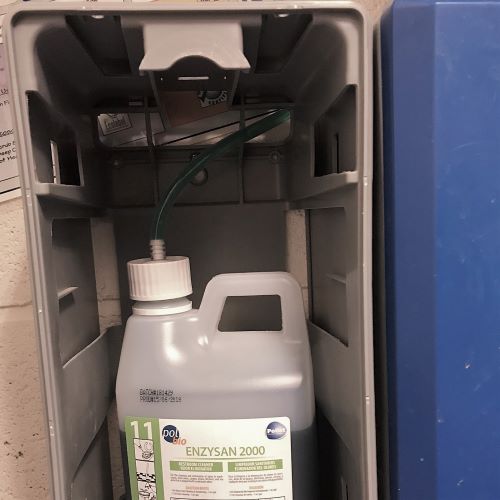
Dilution control devices are regularly used by maintenance in commercial buildings to dilute bulk cleaning concentrates.
They are simple - using the Venturi Effect - and requiring no electrical components. Using the bulk concentrates and simply diluting them
with the device and the water which is piped to the building, can save 70-90% $ vs ready-to-use products.

So, in my quest to start designing my own dilution control device, I knew I had to have a mechanism for recognizing how much liquid product a person is dispensing, so that
I could charge them for that amount. Hence I narrowed in on my H2M project: a liquid flow meter! I wanted it to be able to attach to the existing dilution control device that
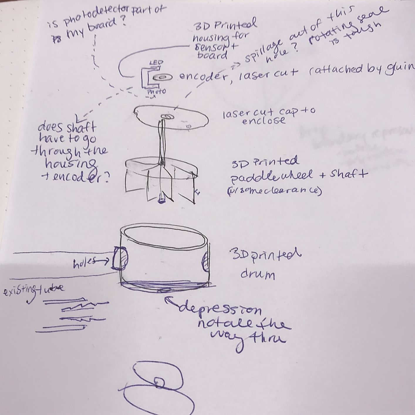
I have -- most likely in the tube after everything has been diluted. I began to sketch out my paddlewheel and the housing for it and to research rotary sensing methods.
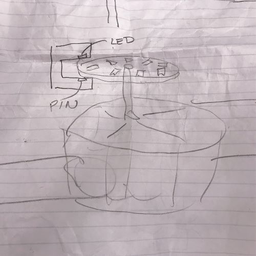
Orginially I was planning on going with an optical rotary encoder where the rotational motion is turned to electrical signals; the interruption of light (LED--> photodetector through a slotted disc) is used
to detect rotation of disc. After talking to a few folks, it seems that optical sensing might be a better option in the future due to its precision, but I decided to start with
magnetic (hall effect) as it seemed a bit simpler.
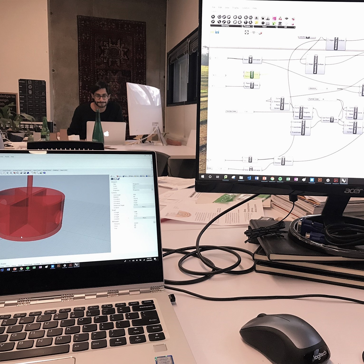
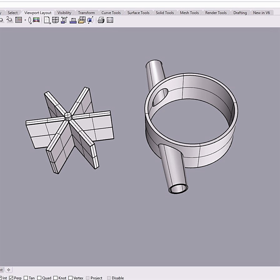
I created some initial sketches of the sensor and how it works with the paddlewheel, and then began work on designing my paddlewheel
using Rhino and a bit of Grasshopper. I began with Grasshopper in case I wanted the whole thing to be parametric, since I wasn't quite sure the size of everything just yet.
I soon found it too confusing to be coding rather than playing around in the Rhino interface so I baked and switched into Rhino.
.
On my initial designs I had a long thin axel on my paddlewheel, but thinking about the fact that liquid was moving through the paddlewheel and a long thin axel wouldn't be able to be as well sealed,
I decided to make it short and hve it fit in indents in the paddlewheel enclosure. (Yesterday I learned that if I had designed it to have a long thin axel, I could you a bearing to close off the hole from leakage;
also I would probably want to add the axel/shaft after 3D prniting, because it would be a difficult thing to print.) I designed the whole object to the dimensions of the liquid dispensing tube
of the device that I had. I made sure to design tapered ends so that the "tubing" from my design could be easily inserted into the tubing of the device. The whole thing was to be 3D printed,
except for the flat caps to the enclosure, which were to be laser cut.
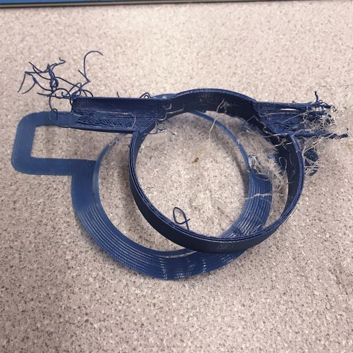
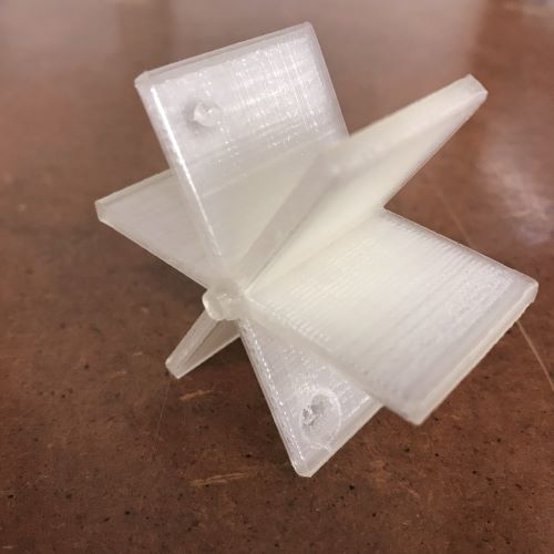
My inital prints failed - the support material was finnicky and messed up the rest of the print, but eventually I got a version printed that looked good to go. Only then did I realize,
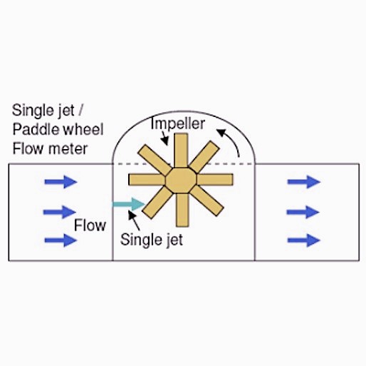
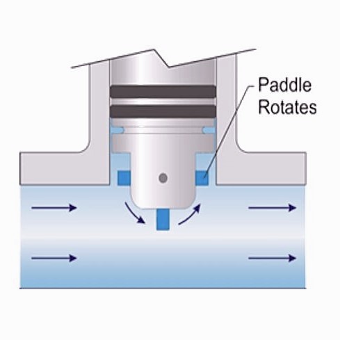
when trying to flow water through it, that the inlet for the water has to be on the edge of the paddlewheel and can't be letting water in straight to the center or else the paddlewheel doesn't easily
turn. (I guess I should have done some more research and paid attention to the fact that most of the examples I saw online seemed asymmetrical!) I redesigned the paddlewheel enclosure to have the inlet and outlet
off-center. After another couple printing failures on the Ultimake with the stiff supports, I decided to splurge for the GSD Objet printer with the mushy supports which dissolve in the chemical bath. This print
had nice resolution and printed well. It was a bit brittle though, and I ended up chipping off a piece when trying to clean it.
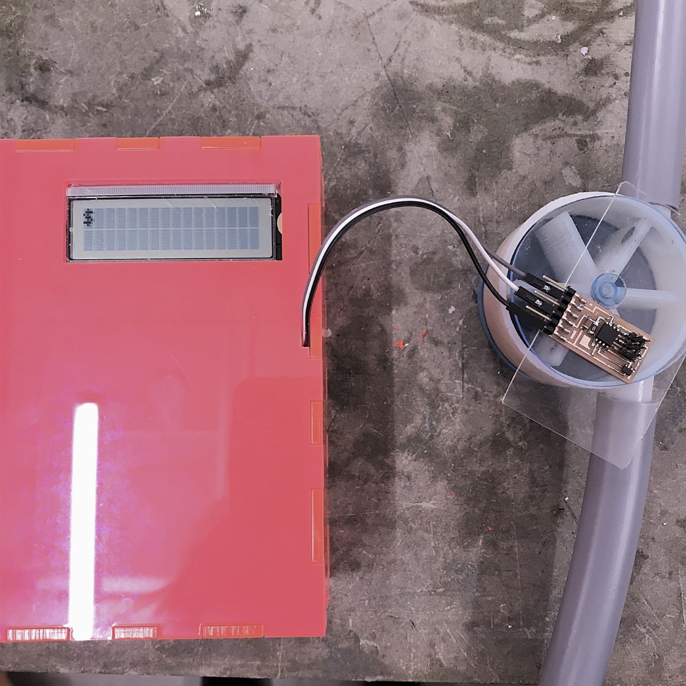
Meanwhile, I was getting started on the board for the hall effect sensor. I knew I was going to use my board that I designed for the LCD to fulfill the final project recquirement
of using a board we made in Eagle, so I went ahead and milled and soldered Neil's board for my hall effect.
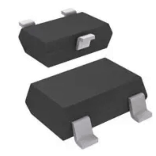
I used the "Hall Effect Sensor Single Axis SOT-23W" as my sensor. I wrote a program
to output the magnetic field reading to the Serial Monitor. I was having a lot of trouble getting this (simple!) program to work. I was changing the pins in the code, the
COM ports, and testing the ATTiny and sensor with the oscilliscope. Eventually I realized I had to swap the RX pin to be TX (even though the schematic png has it labeled as RX,
that is in the persective of the computer, and in this case it is on the input device and it transmitting the signal). I also realized that even though the "Programming an ATtiny w/ Arduino" guide from
High-Low Tech and others say you can use either pin "4" or "A2", my Serial Monitor only worked when I swapped it to A2 (-- this is the frustrating stuff about electronics!).
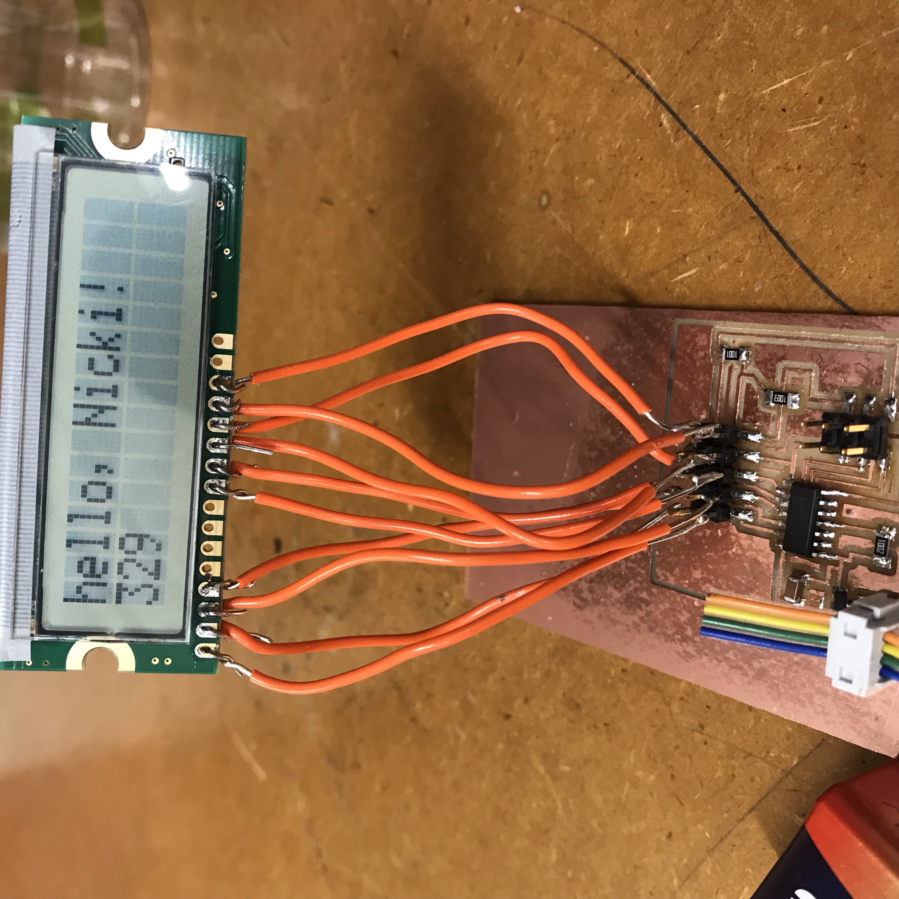
Finally I was getting the right information from the sensor! I set the code so that it would "charge" a few cents for every time the magnetic feild went above 510 -- absent of magnet, it hovered around 508
and when the magnet came close in one direction, it went down to ~504, and in the other direction, up to ~512. I made sure that there would still be these readings through the acyrllic sheet
I had laser cut to enclose th paddlewheel.
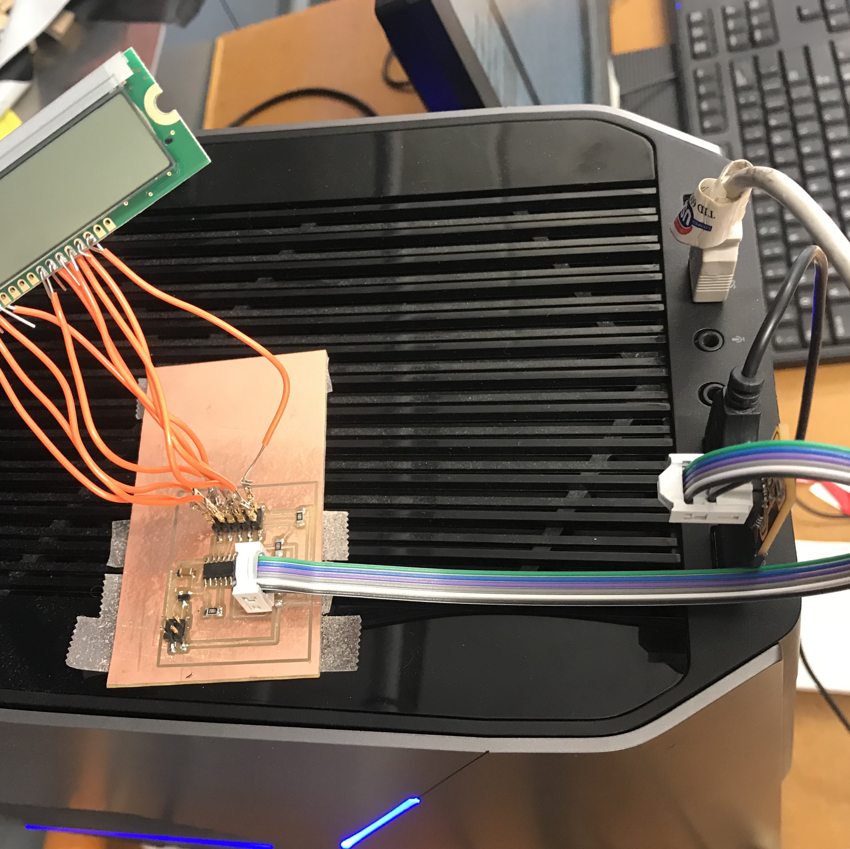
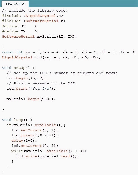
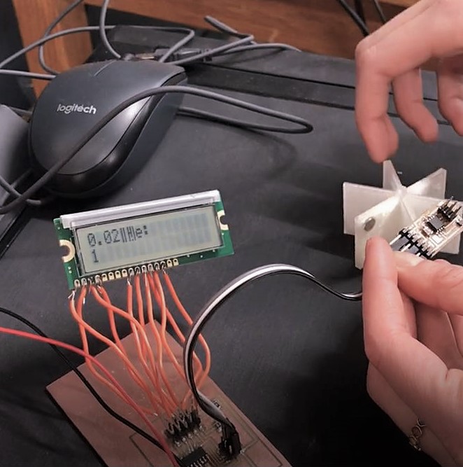
Next up, I had to connect my LCD board that I had designed, to recieve information from Serial so that my input could speak to my output. For this I used a serial bus - connecting
the GND, V, and TX from the input board to GND, V, and an unused MOSI 2x3 pin on my output board. I had to adapt my LCD code so that it could listen and print from Serial.
I found a site with helpful code for reading from Arduino Serial port, and writing to 2x16 LCD.
In the process of loading programs onto both my boards, I accidentally used a 9V battery directly to my input bpard, which doesn't have a regulator, and I blew the ATTiny. After replacing it and
playing around with the code some more, I eventually got the two boards speaking and outputting the right data!

All the steps until now took me multiple days, so I was very relieved to get something working. The next few steps were just the home stretch.
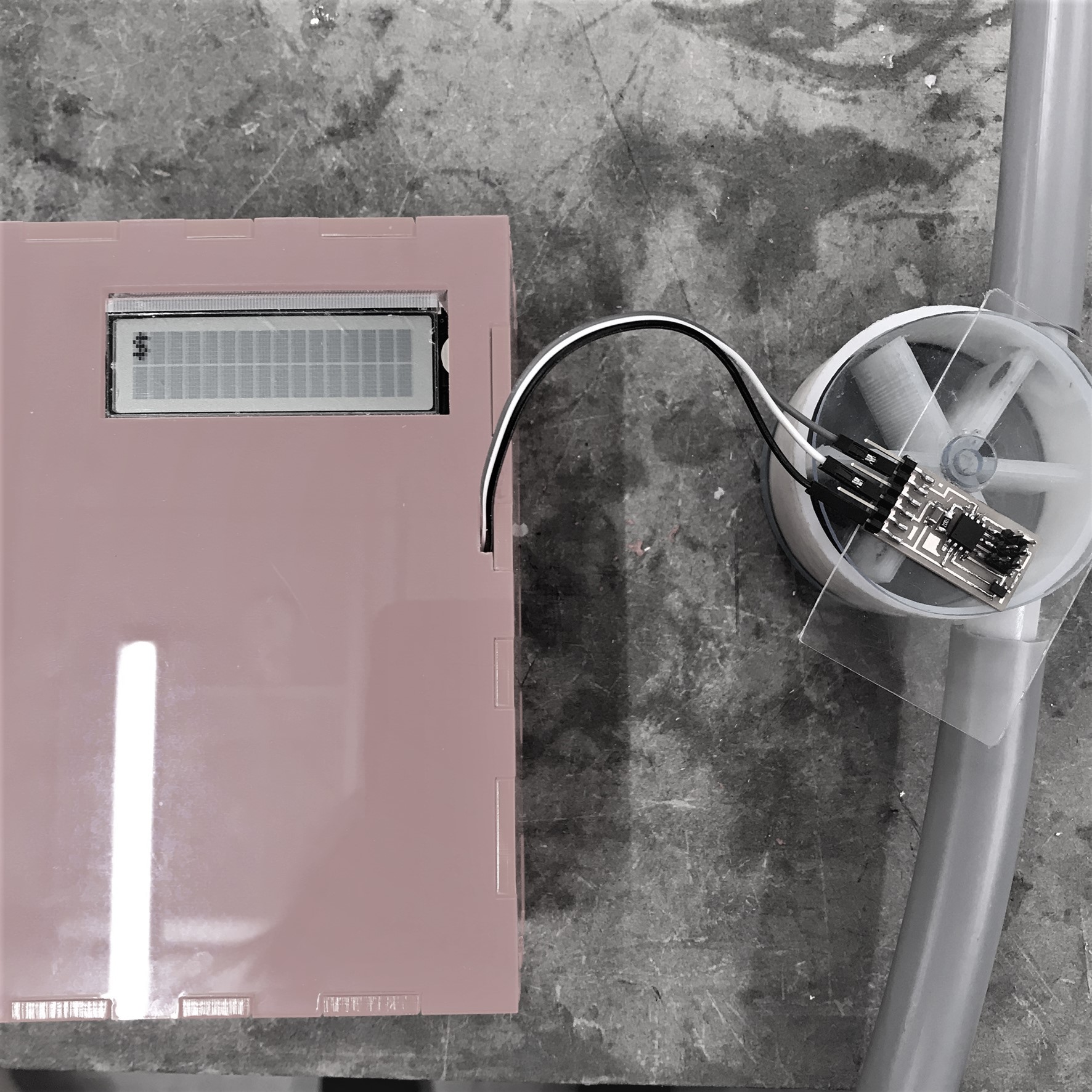
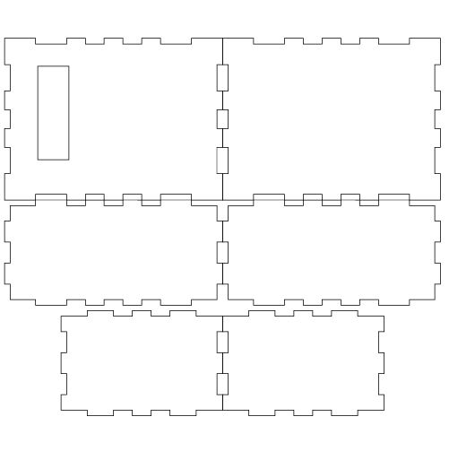
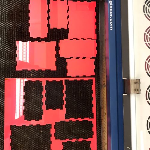
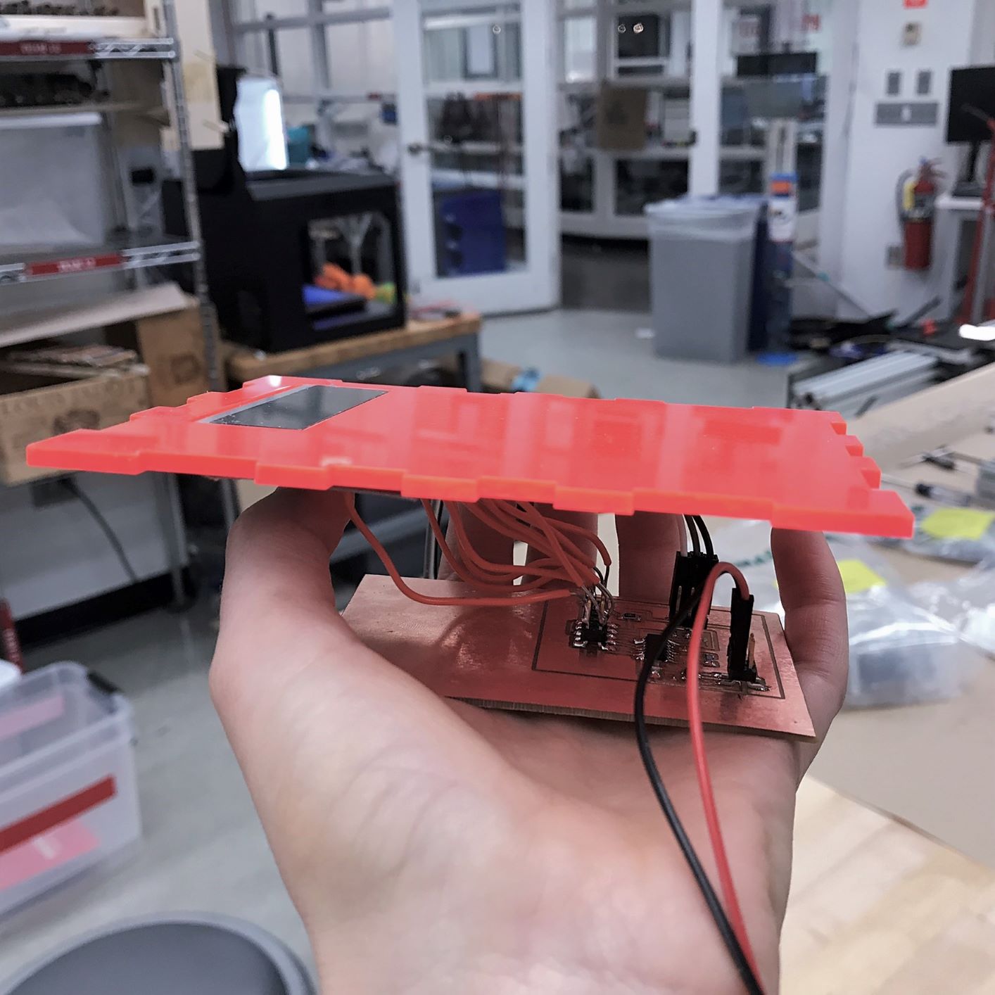
I laser cut a box to house all my electrical components and to fit my LCD nicely. After putting all the components inside I tested everything again and was getting gobbledygook. I didn't understand what was going
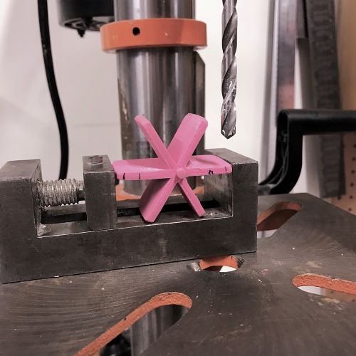
on until I realized one of the LCD wires had come loose. I resoldered. I then used the drill press and a 1/4" bit to create 2 notches on the opposite paddles to inlay/glue
the magnets (2 so that the weight was even). And I vinyl cut a few colorful stickers for the front of my preexisting dilution control machine. I sanded/filed down the paddlewheel so that it
turned smoothly with water or air (there was previously some friction along the edges). Even after sanding/filing, it seemed that the wheel only turned smoothly when water was hitting the paddlewheel
at a certain angle (the paddle had to initially be angled towards the incoming stream.) Because of this, I decided not to glue to top on, and to demonstrate with it open, or holding it closed.
I didn't have enough time left to try another 3D print pass - but in the future, I will design the ppaddlewheel to be smaller and have the water inlet even more off center to ensure good rotary flow.
All in all, I thought this was a successful project. It really helped me understand a lot of the concepts introduced earlier in the class, whih I didn't quite grasp the first time through.
I thought the scope was appropriate for my skill level and it had a bunch of different fabrication elements to it.
I've really enjoyed this semester and look forward to applying the skills I've learned to the dilution control device I'm designing and to other future projects!!
Tools: Ultimaker, Objet, laser cutter, vinyl cutter, drill press, plastic glues, magnets, hall effect sensor, 16X2 LCD