

This week I worked to program my board from Week 5 to have my LED flash once the switch has been flipped. However, my original board from Week 5 could not program. Initially, we couldn't figure out hwy my first board couldn't be programmed as all the connection seemed to be in the correct places. Given that we were unable to find the mistake, I decided to just rebuild my board from the schematic found below. Where the following components correspond to each number.
1) 3 prong switch
2) 500 Ohm Resistor
3) Green LED
4) 2 x 3 ISP Header
5) FTDI
6) 20 Mhz Resonator
7) 10K Resistor
8) 1 micro Capacitor
9) AT Tiny 44 with VCC denoted where the number 9 sits
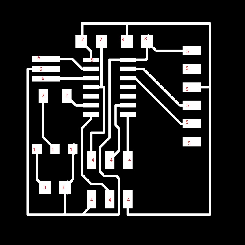
This partcular configuration looks fine. However, the trace running along the inner top half of the left side of the AT Tiny 44 was soo close to where the components of the Tiny 44 itself sat. This means when I actually milled the board, the two parts would fuse into one as seen by the milled board below.
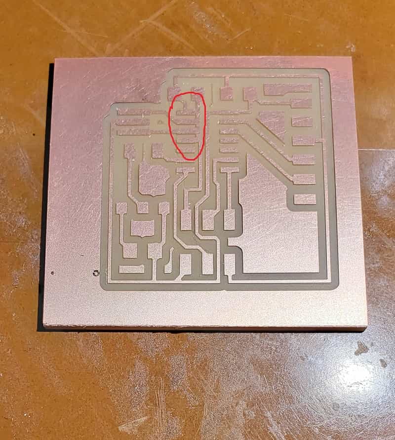
Now that I have found my previous week's mistake, I moved that trace out towards the right, remilled my board and soldered on my components. This time, the board worked and was able to be coded. I used the Arduino IDE and an AT Tiny 44 library to code my board. I created a double trigger switch for my board and decied to keep the work simple so I just coded my board to have a flashing light when the swithc is turned on as seen in the video at the top of this page. The following code was used:
void setup() {
pinMode(7, OUTPUT);
}
void loop() {
digitalWrite(7, HIGH);
delay(100);
digitalWrite(7, LOW);
delay(100);
}
Unfortunately, I wasn't able to create my desired circuit board this week, which was a breakbeam sensor. This would have contributed to my final project as the element that determines when a game finsihes in my pinball machine. This element will be brought back to be produced during the output and input week.