Work Progress
I have been working on input and output devices communication for weeks. For those weeks, I spent so many times on the ESP32 debugging
and got nothing solved, which makes me be so despair about the foreseeable failure of my final project. This wildcard week, however,
saved my final project.
I joined the advanced embedded programming group and was hoping working on microcontrollers with larger storage for my final project and
learning how to burn bootloader and programming different types of microcontrollers in this week.
On 4pm Thursday at CBA offices, we meet with Erik for a brief introduction about SAMD11 and OpenOCD,
a free software on-chip debugging,in-system programming and boundary-scan testing tool for ARM systems. He gives a very solid tutorial
and documentation about setting up OpenOCD in windows system with a downloaded binaries, programming/debugging with OpenOCD, burning an Arduino compatible bootloader
with OpenOCD, and setup and programming with the Arduino IDE in the gitlab page.
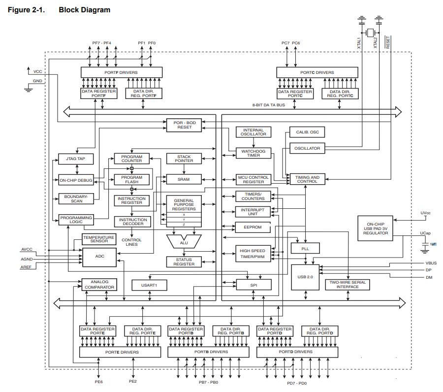
As far as I understand, SAMD11 is an ARM controller. ARM is a family of RISC processor architectures. In particular, we'll be looking at ARM
Cortex-M processors, which are designed for microcontrollers. Unlike the 8 bit ATTINY chips we've been using, ARM microcontrollers are
32 bits. On average they also support faster clock rates and have more advanced peripherals. This means they can handle more demanding
compute tasks, but also that they tend to have steeper learning curves. With the tools linked here you'll be up to speed in no time.
However, although being powerful, this microcontroller is also much harder to control. Because I have already run out of time, I do want
to make sure my final project went smooth. Thus, instead of SAMD11, I found that the previous year is working on the USB Profile(with
Atmega16u4).
There were several ways I can do to communicate my input devices and output devices.
Thus, as suggested by Alex, I started with Atmega16u4. Compared with Atmega16u2, 16u4 has ADC and more pins. I didn’t use Atmega328p at the beginning is because I am a little bit refuse to use this chip that Arduino uses.However, compared with atmega328p. the resources and introduction for designing a board for 16u4 is very few. I only found one or two precedents with useful tutorials in the fab page who worked with this microcontroller.
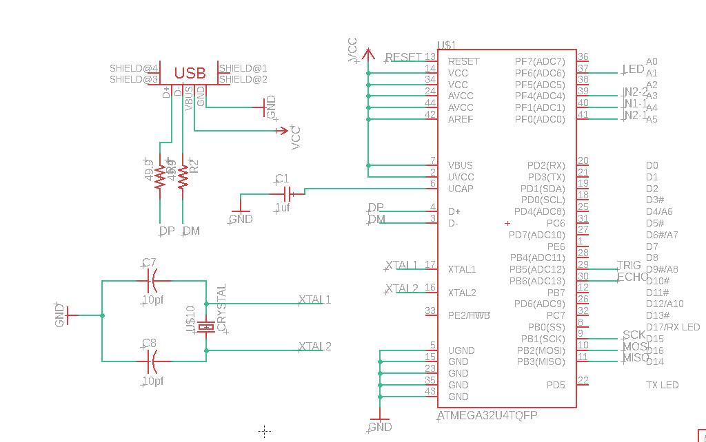
Schematic
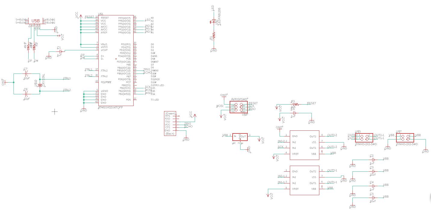
Basics
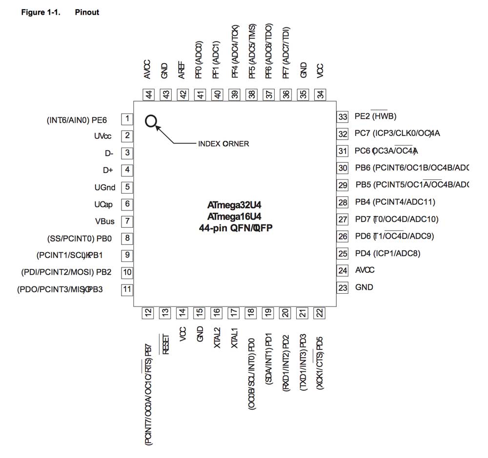
Some Notes to the schematic design for Atmega16u4(check the datasheet here)
A huge mistake I have made for this board is that I didn’t notice in Andre Mao's documemtation, he did point out that the pin for the atmega16u4 is too thin and a 1/64’’ mill cannot go through. To change the pad size, here is a process cited from Shaoxiong Wang’s page.
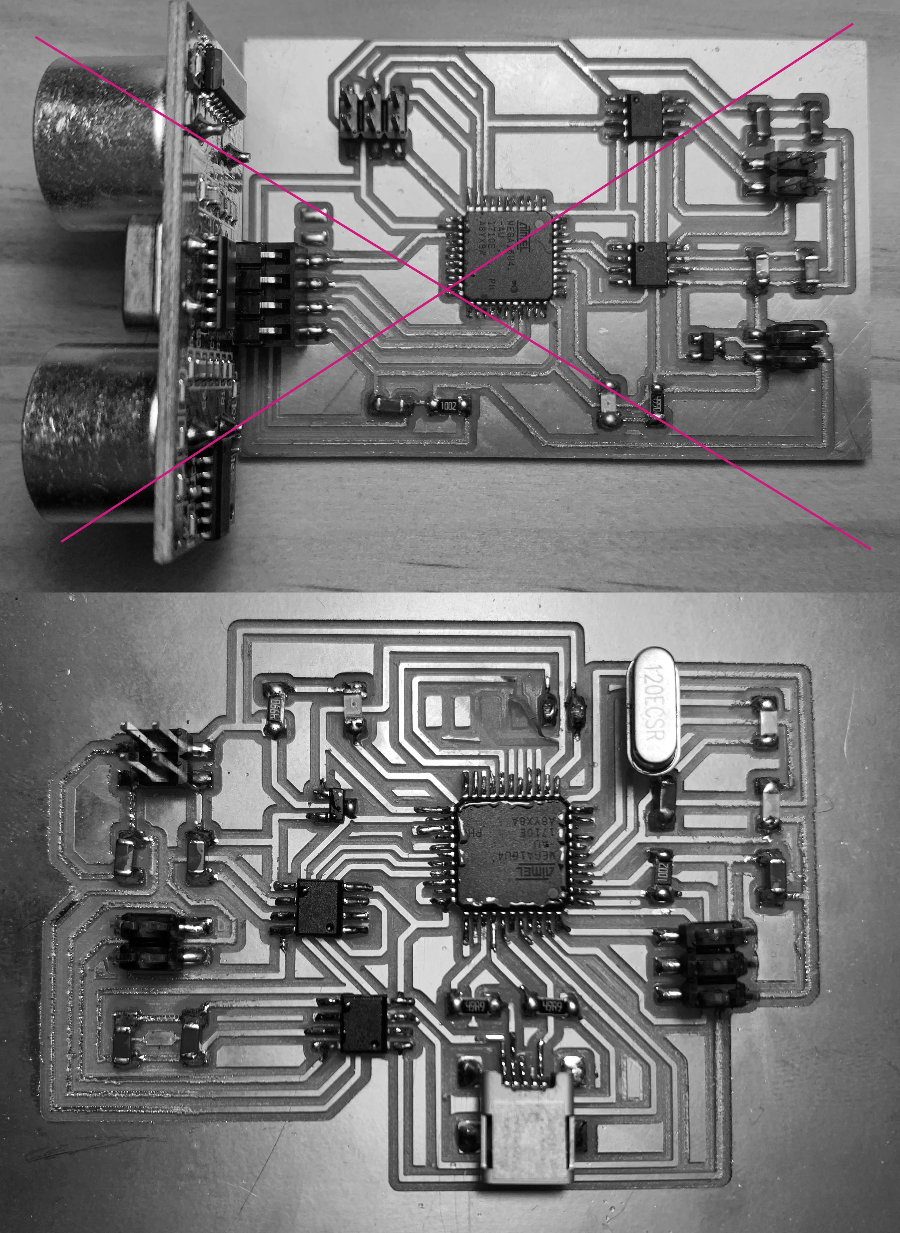
Bad traces
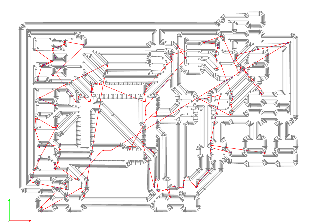
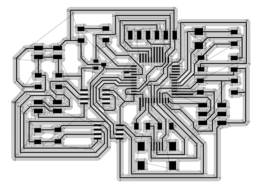
But here comes another unexpected problem, I have done a lot of boards for this semester but I have never imagined I will be stucked at the mill phase.
Because the traces are too thin, a lot of them are easy to be damaged and fly away and make my board become a trash then. The pin traces that haven’t been pulled out are so tiny and were always disappear when it comes out of the machine. After several failure, I went back to my trace and extend those pins to be longer.
My traces struggling.
However, the problem is not solved. The nightmare lasted for 2 days and I spent hours and hours on milling a board and I only got one usable board. It was Anthony pointed to me that I finally realized the problem is partially caused by the thin traces, but most likely because the three mills in our arch lab are bad and should be replaced.
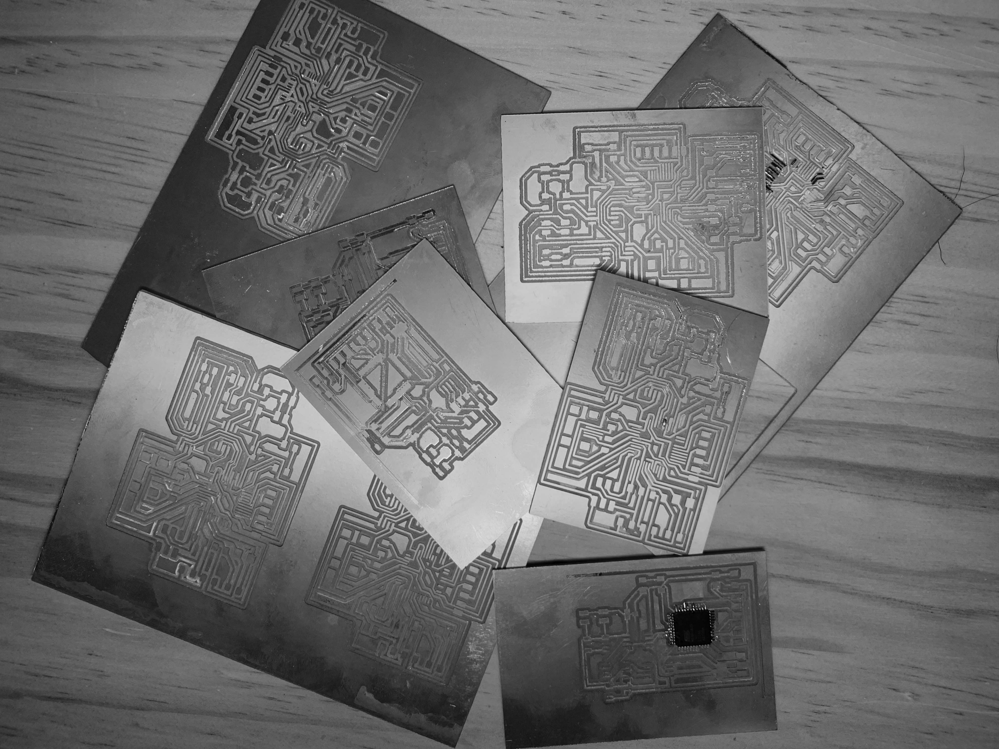
A big lesson: If the board edge is rough, it means the tool should be changed.
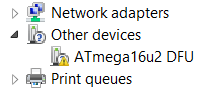
Another lesson comes soon. After I finally completed the board of atmega16u4 and it was detected by the computer with its USB port, but I found that I could not program it in Arduino. Th programming of Atmega16u4 only works with DFU Programmer. I do not have any foundation of C. In the command prompt, the only code I have been uploaded are examples given by Neil.
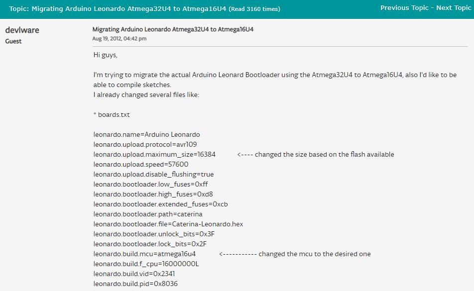
Anthony helped me search for a lot of solutions for programming the 16u4 in arduino. However, there is little resources about this microcontroller.
Although it is possible that you can use Arduino Leonardo, there will be a lot of problems happened because Leonardo is for 32u4, and it is very hard to migrate 16u4.
I programmed my board in the command prompt with the basic hello world script as the ending of using this chip and decided to work with a more promising microcontroller, Atmega328p.
This week is the most frustrating week for the semester, but I had some take-aways from those mistake I had made.
Before choosing a microcontroller, always to make sure it has enough storage, you can program it with your comfortable environment, and you are able to mill it with your tool.
We have a plenty of examples and tutorials about making a fabduino based on Atmega328p. There are also much resources about the microcontroller bugging online, which gave me much more confident.
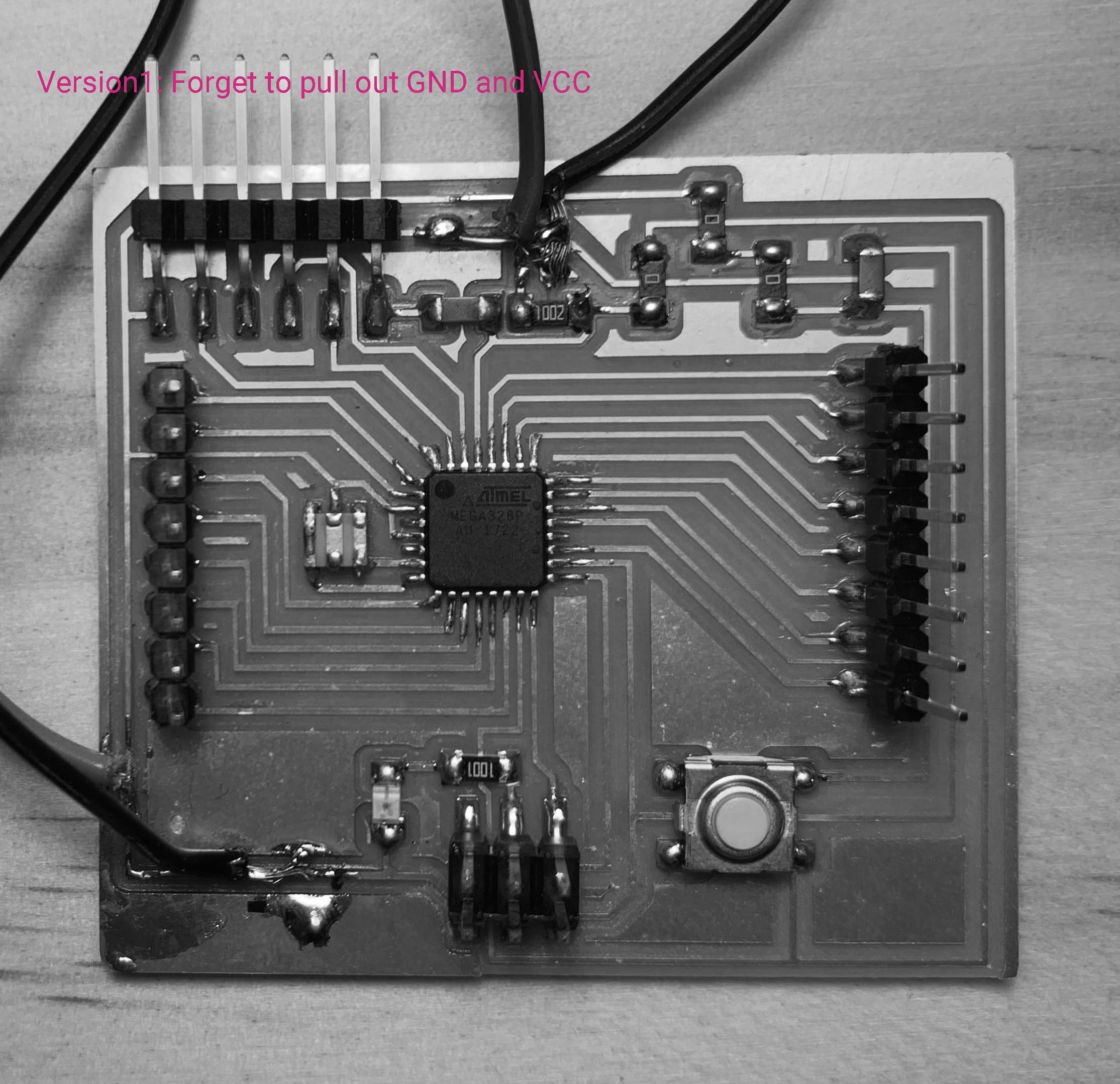
It is better to work with a control board with its pins to be all pulled out and connected with smaller board than a large board that has more possibility of failure.
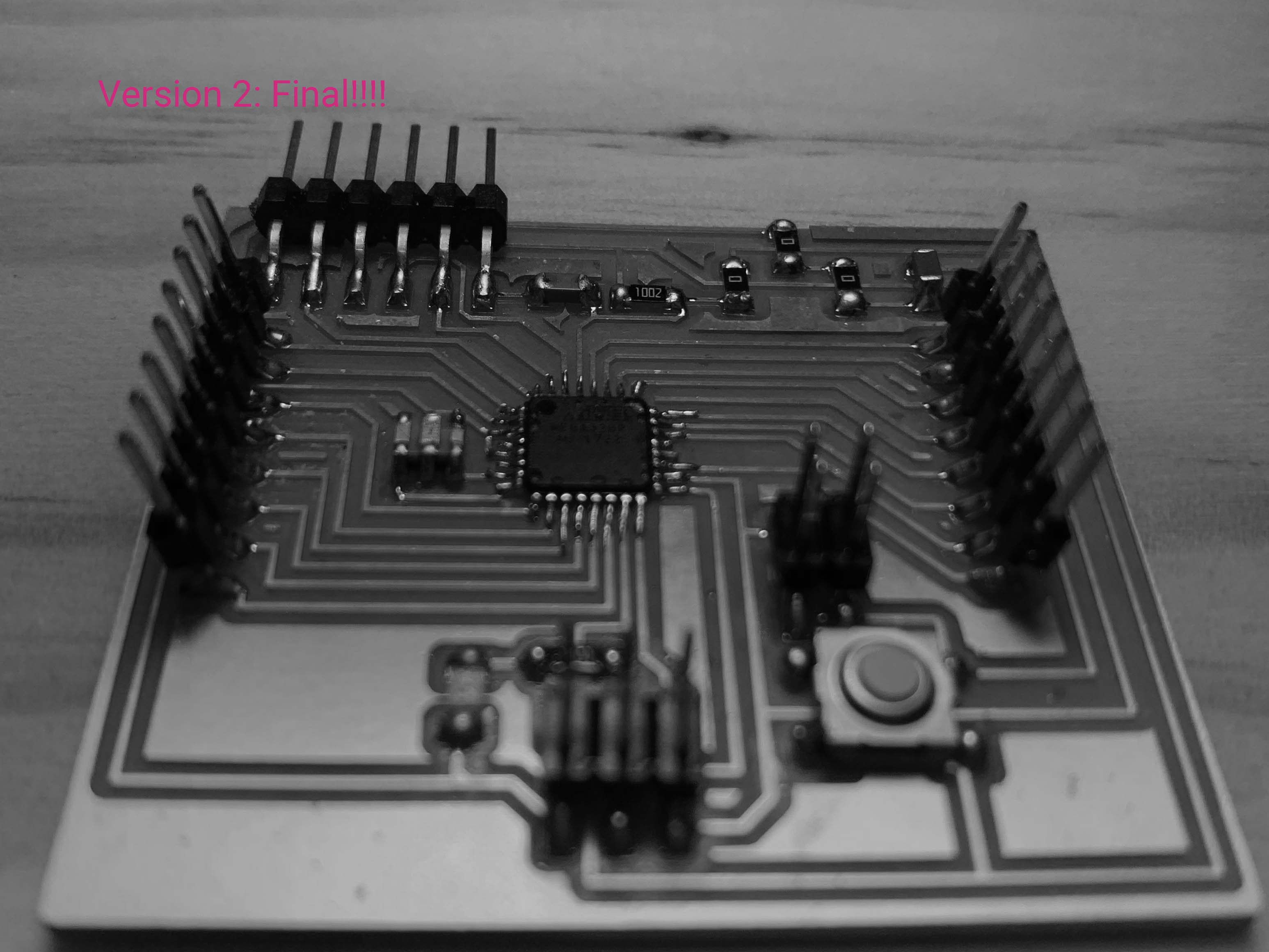
Schematic
Board
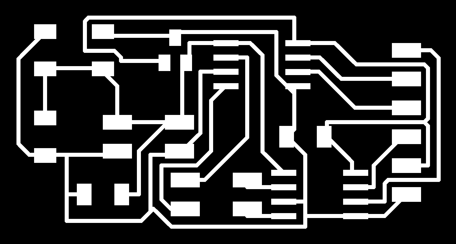
With the previous experience, working with atmega328 is much easier than atmega16u4, I changed the tool and was very cautious about if the tool can cut through my traces. Again, I use photoshop layers to check this.
Finally comes to programming part, this Fabkit tutorial is very intuitive. The most important thing you should know before programming Fabduino in Arduino IDE is to add the following script to board.txt file. The board.txt file is usually located at Arduino’s program file>hardware>avr. However, the board.txt syntax for windows system follows the Linux format and is not compatible to the add-on script.(the backsplash issue)
Erik helped me on this, he changed the syntax(which I have no idea)and also taught me how to burned the bootloader in Atmel studio.
Note: Atmega328p can't be burned by OpenOCD
Steps to Burn the Bootloader in Atmel Studio can be found on this page
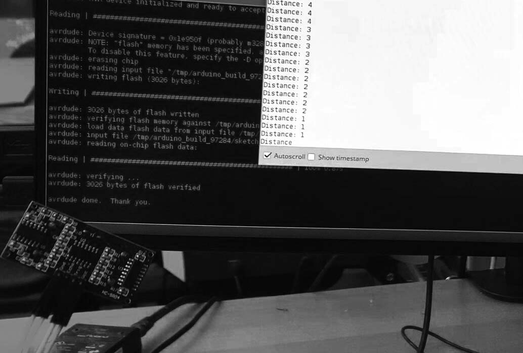
Now I am good to upload my code and connect the Fabduino with my small bipolar motor board.
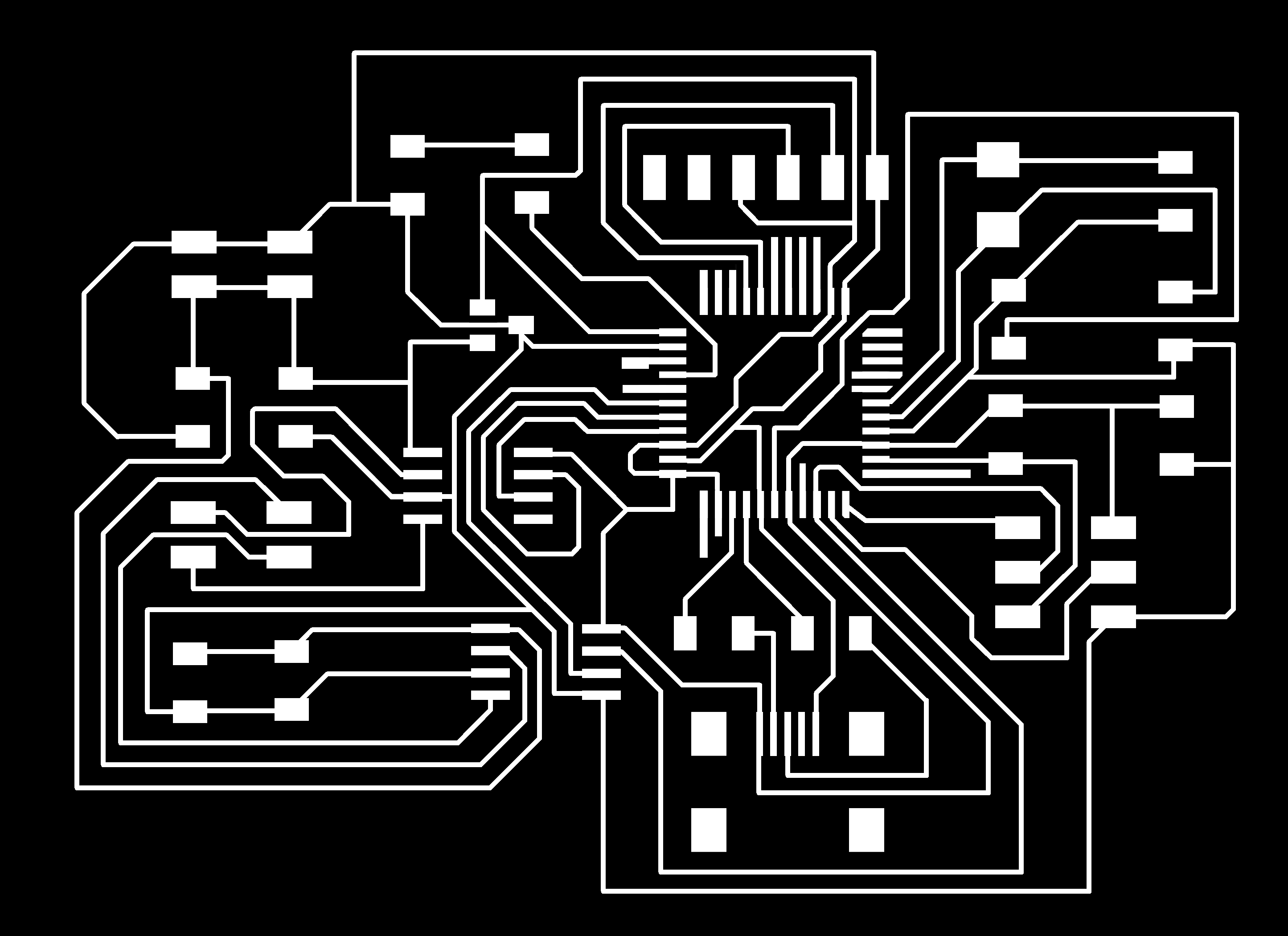
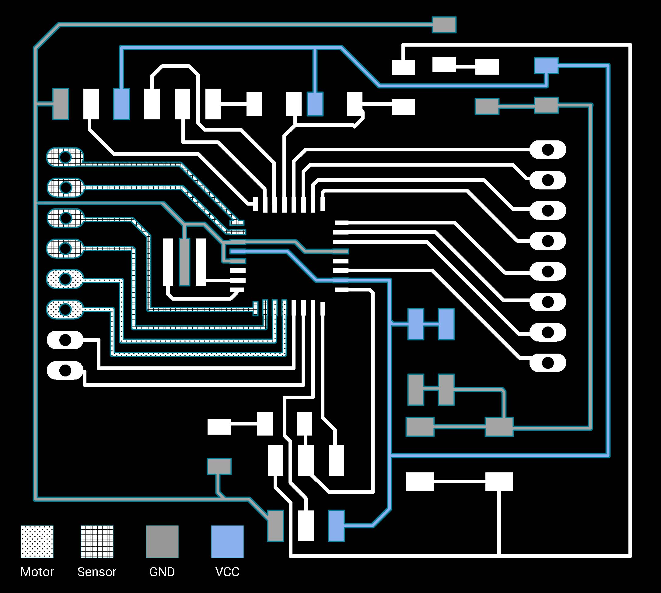
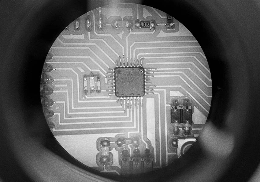
Board traces
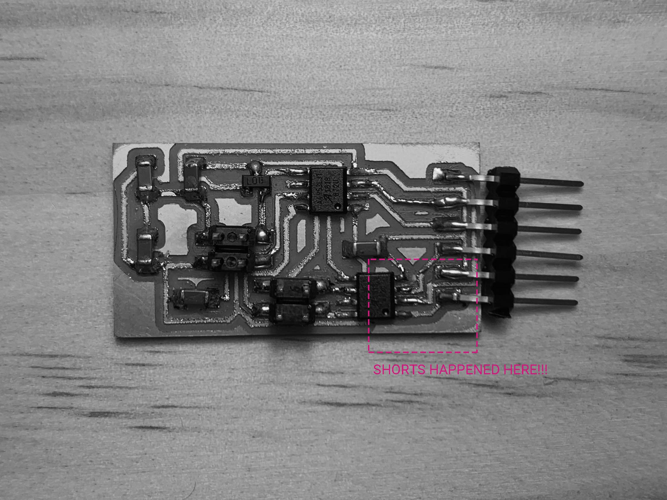
Another nightmare! Although my Fabduino board are able to read sensor data and blink code
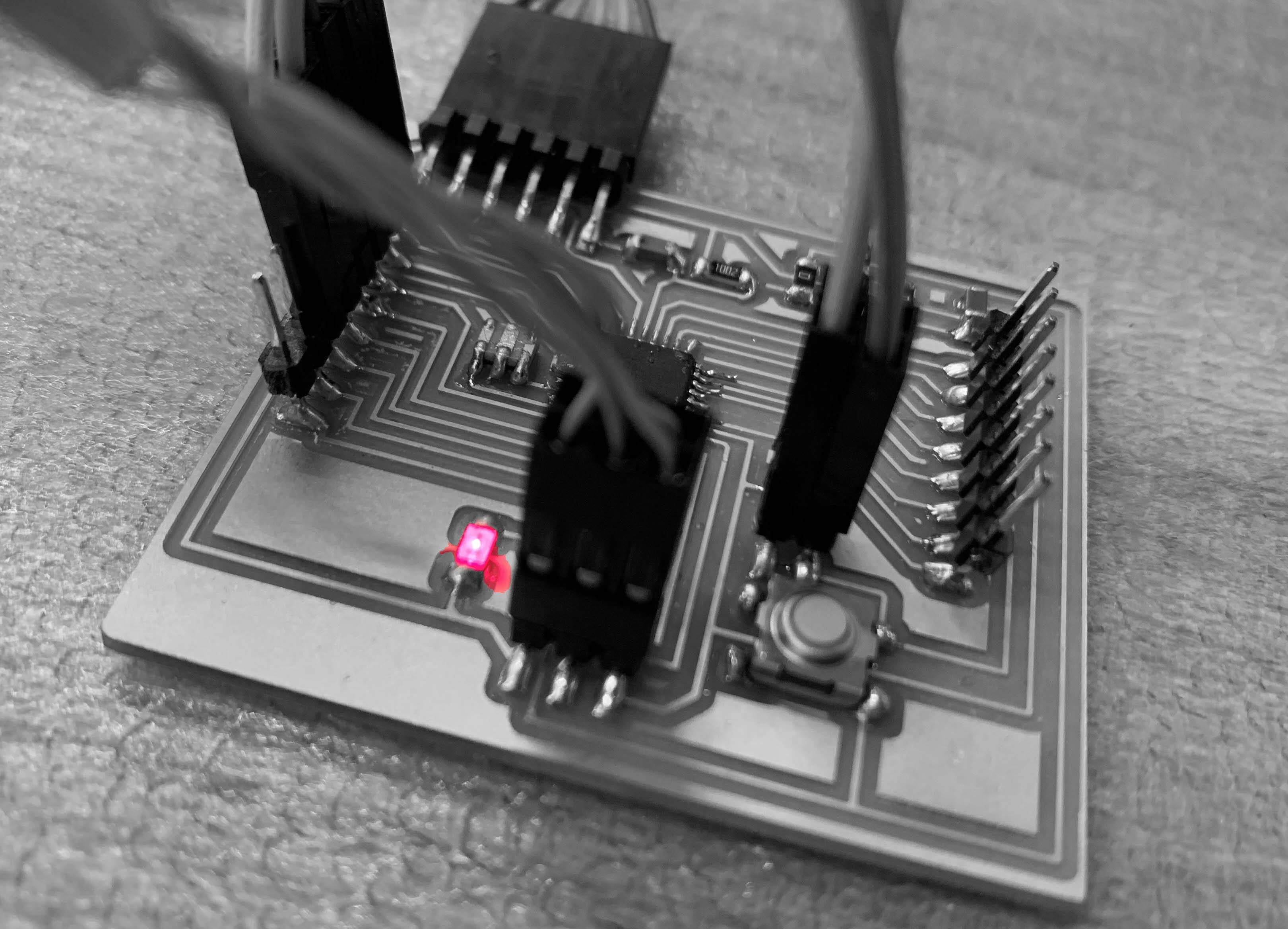
the bipolar motor got really hot and burns once its VCC and GND connected to the Fabduino.(This indicated a shorts) Anthony helped me check my schematic and board and we found that there are shorts happened because there is a spot that the mill didn’t cut through.
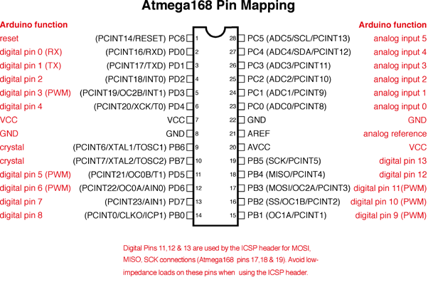
Code
Something about pins:
Finally, I got my input device talk to the output device.