Tracking
Demo and Process
Concept and Precedents
The inspiration of the final project came from the multi-purpose auditorium of GSD. The huge space is separated by a flexible flowing barrier, but the space on both sides can be immediately connected as long as the curtain is pulled back. While I observed how they used the room, I think it is a very interesting architectural concept.
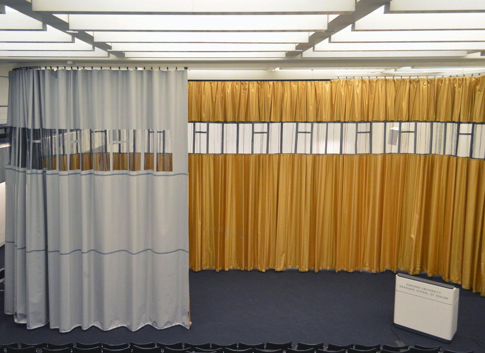
Yellow curtain that divided the space flexibly.
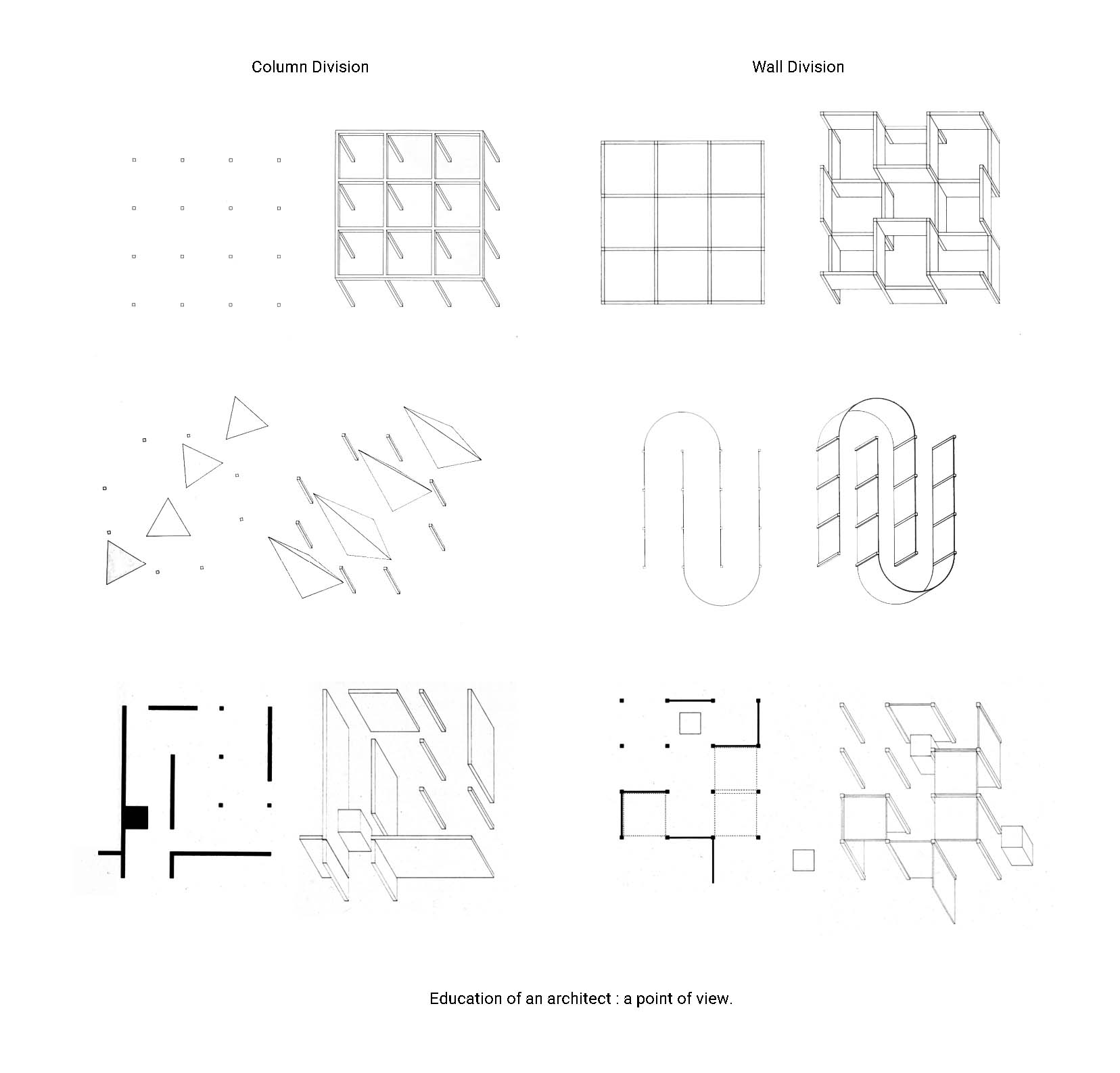
For a long time, architects have been discussing the function and division of architectural space. The space scale, height, size, directivity, light and shadow, and sense of arriving will help render atmosphere and give people different spatial experiences and rhythmic sequences psychologically. The experience of visual space mainly depends on the boundary (including borderless boundary). The traditional way of dividing space includes wall and column net. The former delimits the space into fixed patterns and functional blocks, while the latter opens the space without the sense of rhythm and emphasis in the vision. In my opinion, between these two extreme segmentation methods, the advantage of bringing elements of curtain into the space lies in its flexibility and variability. The Curtain is a neutral medium. Depending on the needs, the curtain slides on a slide track that defines function and user behavior. When space functions need to be completely divided (one side is the lecture hall, the other is the screening hall), the curtain becomes a soft wall for architectural functions, and when people need a wide space, it can also shrink without occupying any sense of existence.
Therefore, in my final project, I hope to study a curtain system that intelligently adjusts the spatial scale. Limited by my limited knowledge of electronics, I have simplified the concept. I tested its performance on a track with a simplest curve outline (with only one curve). The basic mechanism is that if a sensor senses someone approaching the curtain, the curtain will begin to move.
What I have been working on?
I have been working on input and output devices communication for weeks. For those weeks, I spent so many times on the ESP32 debugging and got nothing solved, which makes me be so despair about the foreseeable failure of my final project. This wildcard week, however, saved my final project.
I joined the advanced embedded programming group and was hoping working on microcontrollers with larger storage for my final project and learning how to burn bootloader and programming different types of microcontrollers in this week.
On 4pm Thursday at CBA offices, we meet with Erik for a brief introduction about SAMD11 and OpenOCD, a free software on-chip debugging,in-system programming and boundary-scan testing tool for ARM systems. He gives a very solid tutorial and documentation about setting up OpenOCD in windows system with a downloaded binaries, programming/debugging with OpenOCD, burning an Arduino compatible bootloader with OpenOCD, and setup and programming with the Arduino IDE in the gitlab page.
As far as I understand, SAMD11 is an ARM controller. ARM is a family of RISC processor architectures. In particular, we'll be looking at ARM Cortex-M processors, which are designed for microcontrollers. Unlike the 8 bit ATTINY chips we've been using, ARM microcontrollers are 32 bits. On average they also support faster clock rates and have more advanced peripherals. This means they can handle more demanding compute tasks, but also that they tend to have steeper learning curves. With the tools linked here you'll be up to speed in no time. However, although being powerful, this microcontroller is also much harder to control. Because I have already run out of time, I do want to make sure my final project went smooth. Thus, instead of SAMD11, I found that the previous year is working on the USB Profile(with Atmega16u4).
There were several ways I can do to communicate my input devices and output devices.
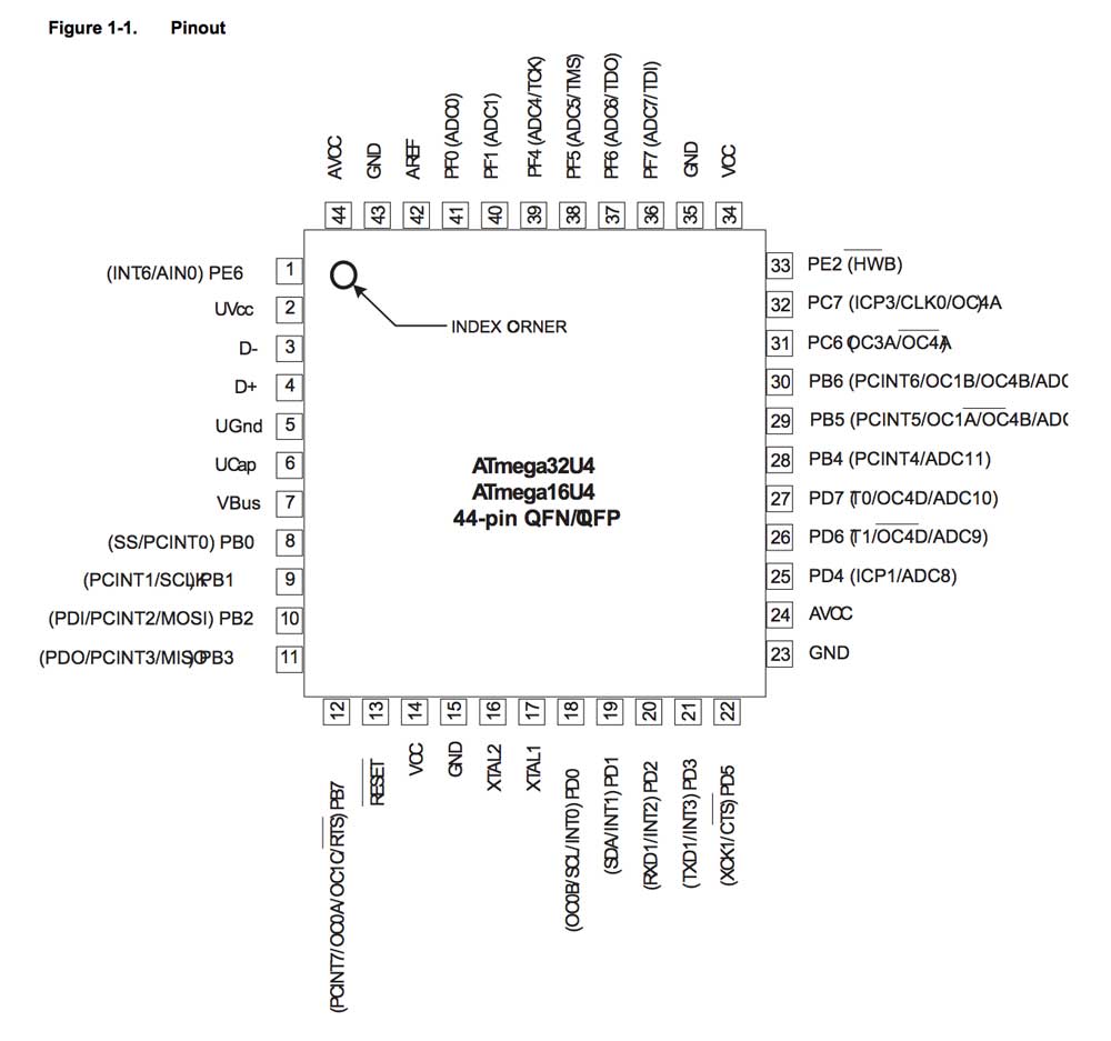
Thus, as suggested by Alex, I started with Atmega16u4. Compared with Atmega16u2, 16u4 has ADC and more pins. I didn’t use Atmega328p at the beginning is because I am a little bit refuse to use this chip that Arduino uses.However, compared with atmega328p. the resources and introduction for designing a board for 16u4 is very few. I only found one or two precedents with useful tutorials in the fab page who worked with this microcontroller.
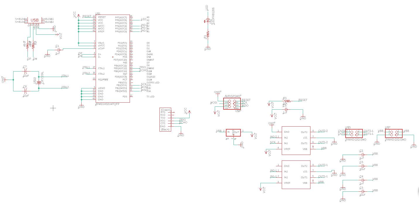
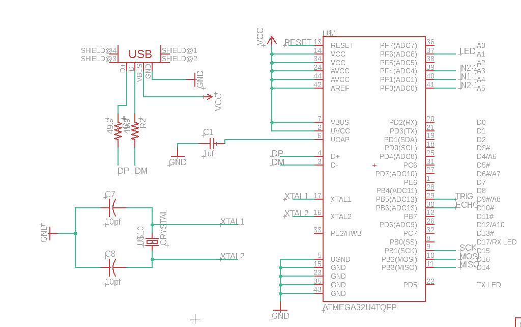
Schematic
Basics
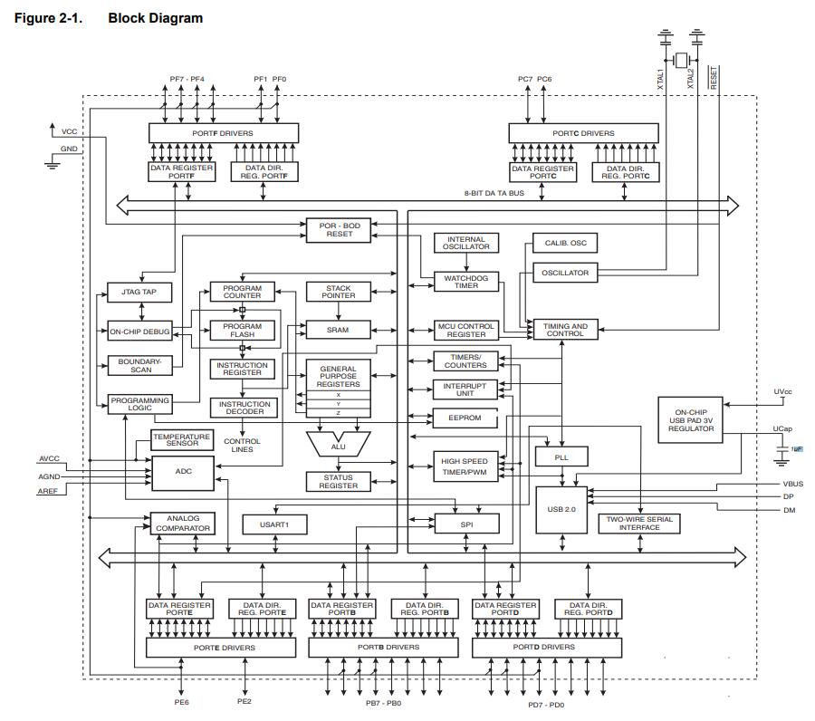
Some Notes to the schematic design for Atmega16u4(check the datasheet here)
A huge mistake I have made for this board is that I didn’t notice in Andre Mao's documemtation, he did point out that the pin for the atmega16u4 is too thin and a 1/64’’ mill cannot go through. To change the pad size, here is a process cited from Shaoxiong Wang’s page.
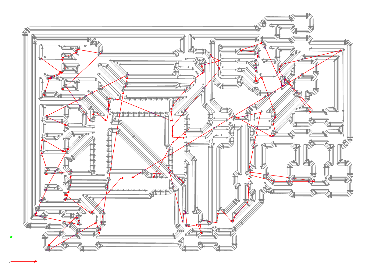
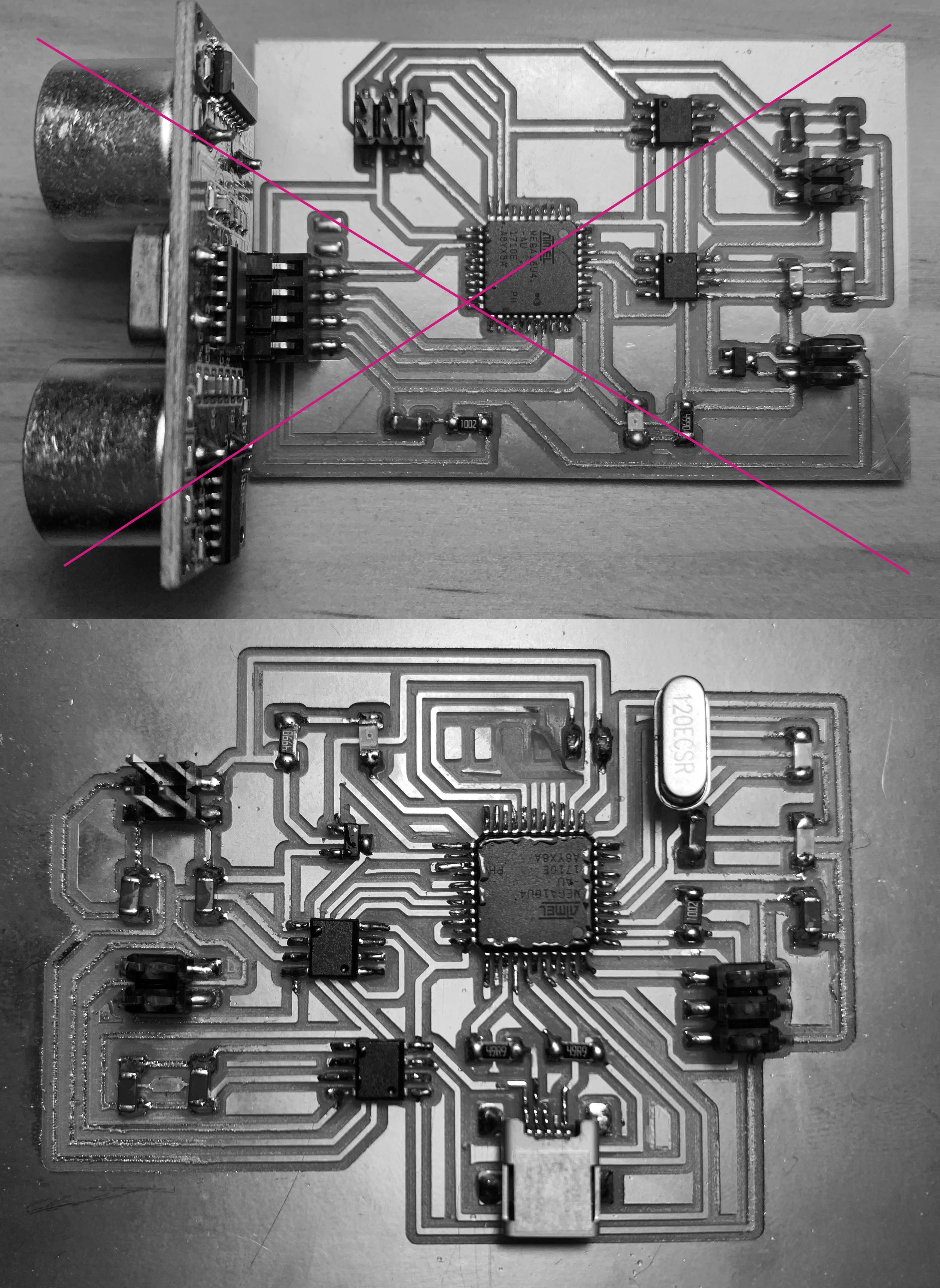
Bad traces
But here comes another unexpected problem, I have done a lot of boards for this semester but I have never imagined I will be stucked at the mill phase.
Because the traces are too thin, a lot of them are easy to be damaged and fly away and make my board become a trash then. The pin traces that haven’t been pulled out are so tiny and were always disappear when it comes out of the machine. After several failure, I went back to my trace and extend those pins to be longer.
My traces struggling.
However, the problem is not solved. The nightmare lasted for 2 days and I spent hours and hours on milling a board and I only got one usable board. It was Anthony pointed to me that I finally realized the problem is partially caused by the thin traces, but most likely because the three mills in our arch lab are bad and should be replaced.
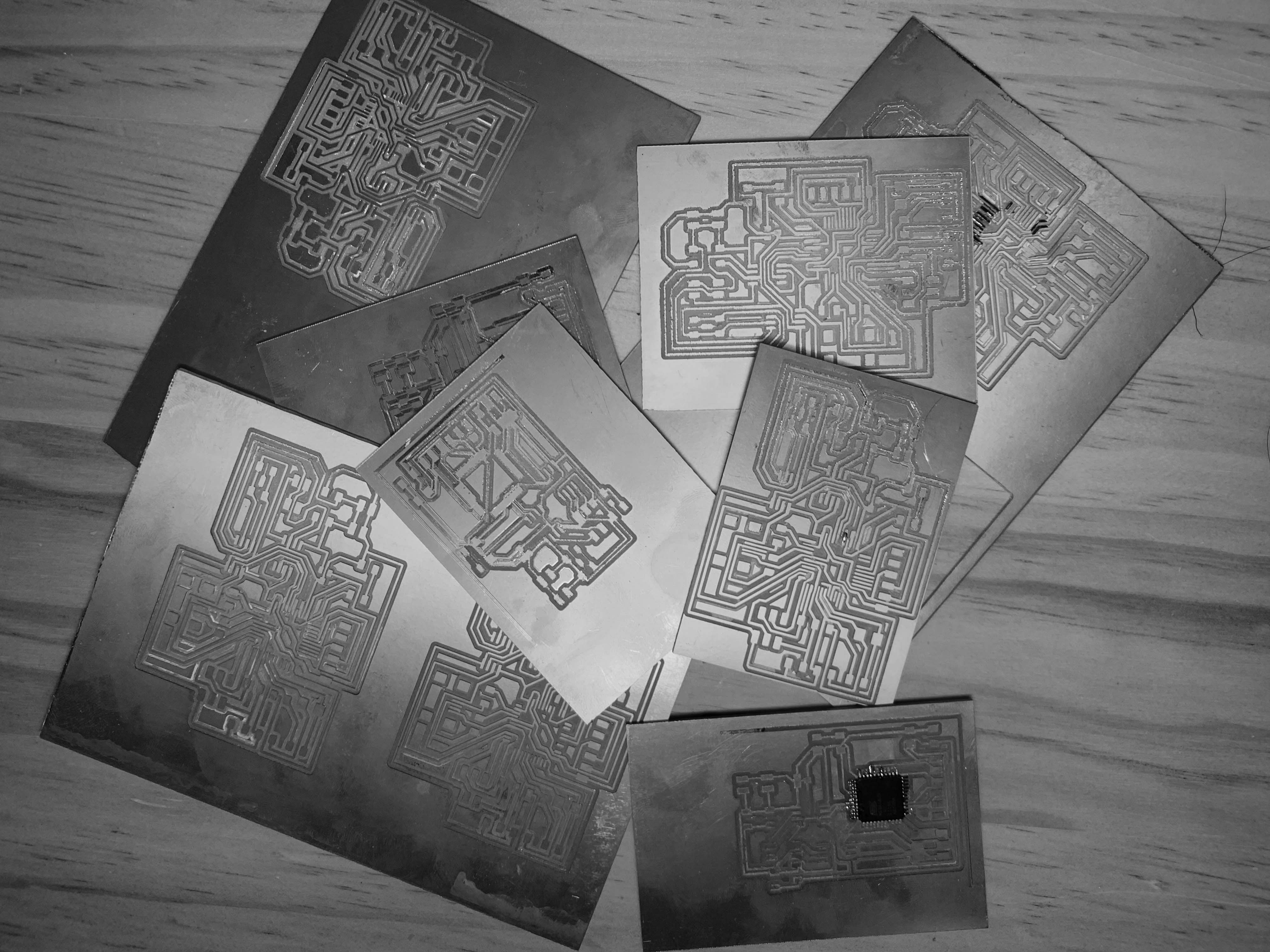
A big lesson: If the board edge is rough, it means the tool should be changed.
Another lesson comes soon. After I finally completed the board of atmega16u4 and it was detected by the computer with its USB port, but I found that I could not program it in Arduino. Th programming of Atmega16u4 only works with DFU Programmer. I do not have any foundation of C. In the command prompt, the only code I have been uploaded are examples given by Neil.
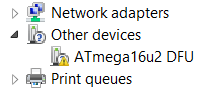
Anthony helped me search for a lot of solutions for programming the 16u4 in arduino. However, there is little resources about this microcontroller.
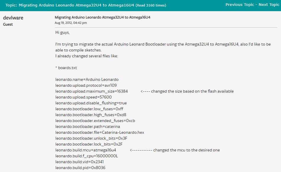
Although it is possible that you can use Arduino Leonardo, there will be a lot of problems happened because Leonardo is for 32u4, and it is very hard to migrate 16u4.
I programmed my board in the command prompt with the basic hello world script as the ending of using this chip and decided to work with a more promising microcontroller, Atmega328p.
This week is the most frustrating week for the semester, but I had some take-aways from those mistake I had made.
Before choosing a microcontroller, always to make sure it has enough storage, you can program it with your comfortable environment, and you are able to mill it with your tool.
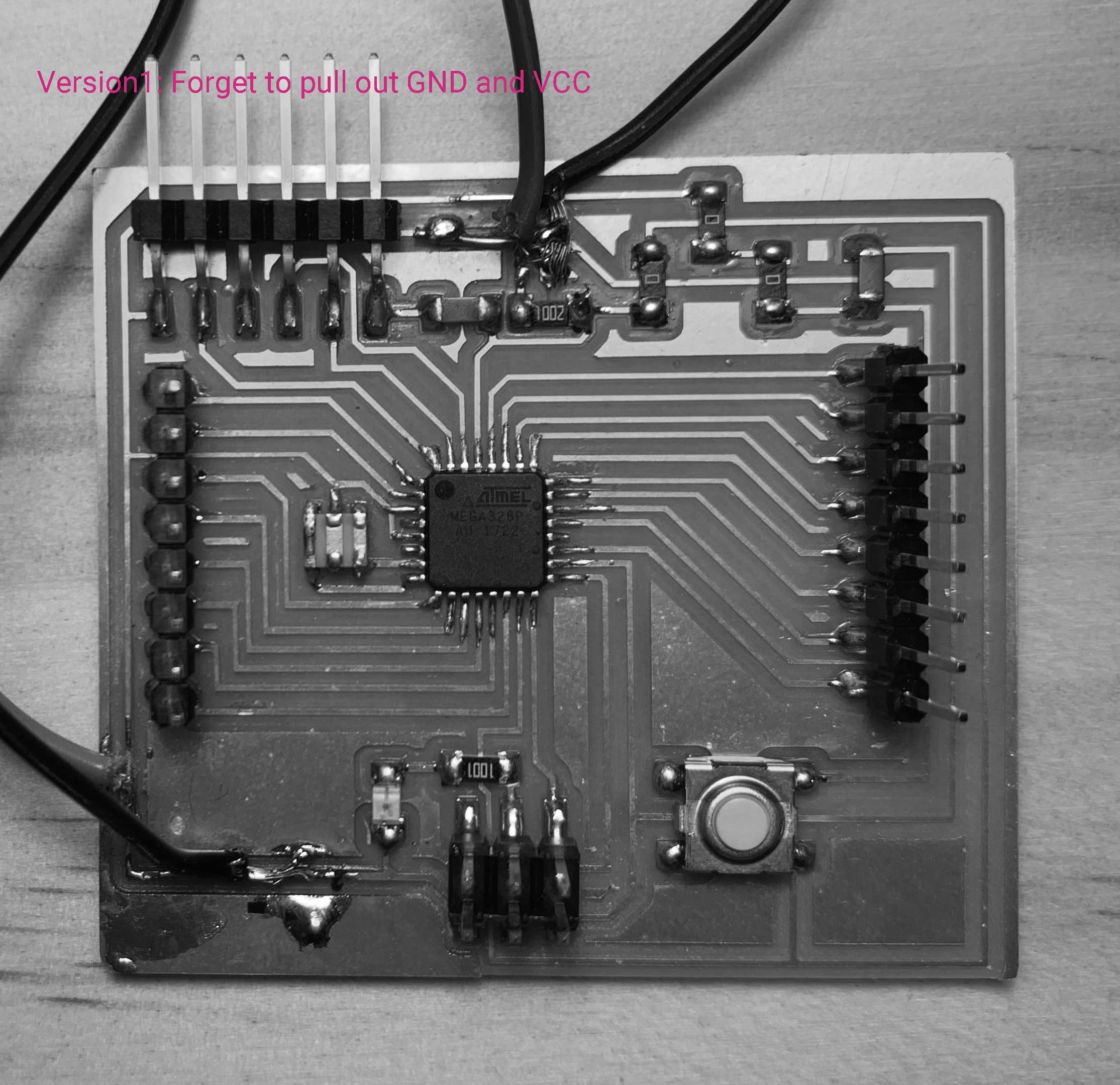
We have a plenty of examples and tutorials about making a fabduino based on Atmega328p. There are also much resources about the microcontroller bugging online, which gave me much more confident.
It is better to work with a control board with its pins to be all pulled out and connected with smaller board than a large board that has more possibility of failure.
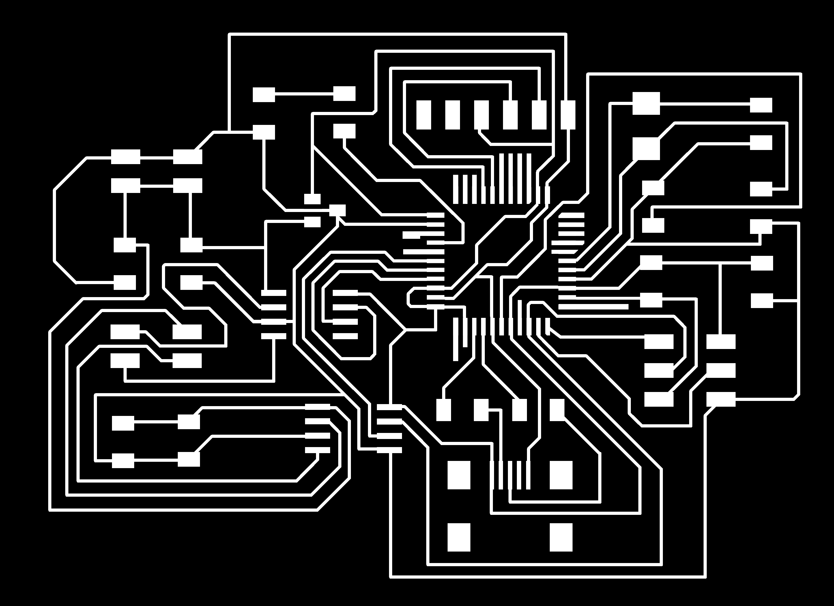
Schematic
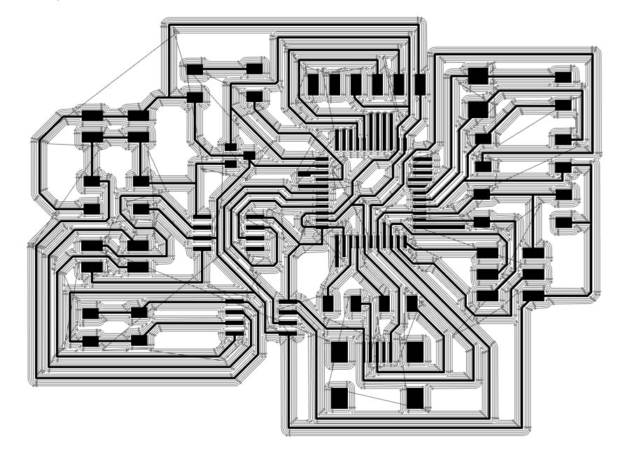
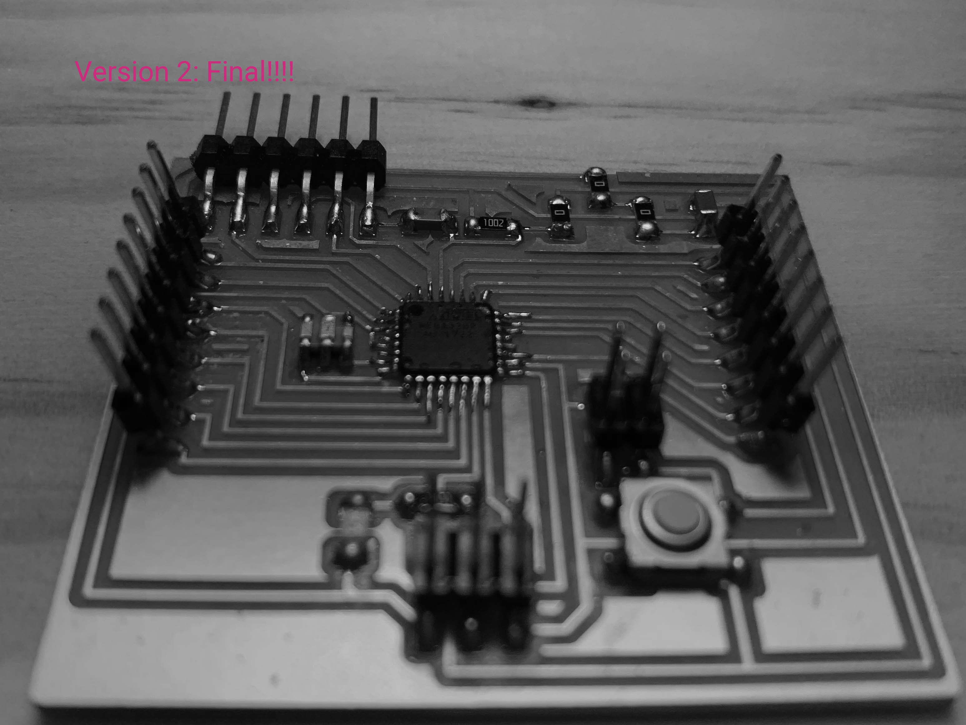
Board
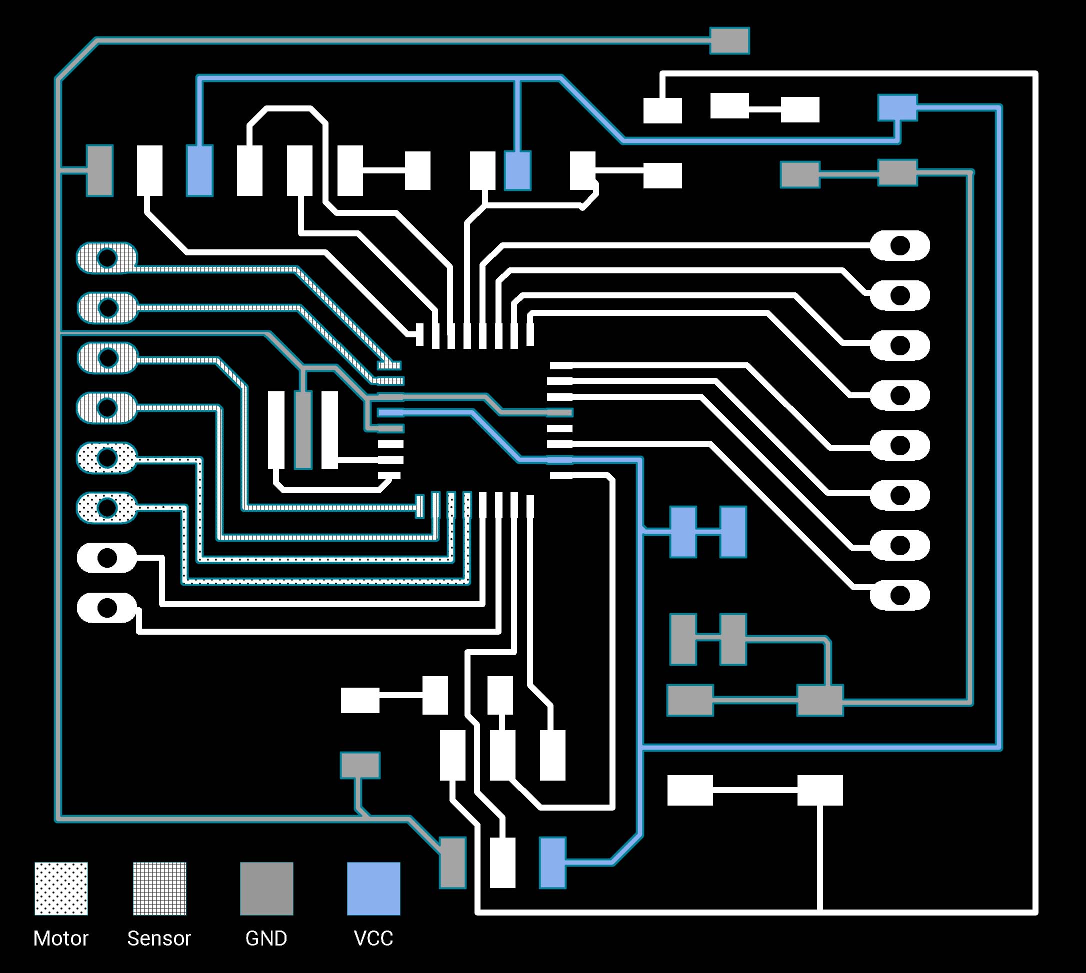
With the previous experience, working with atmega328 is much easier than atmega16u4, I changed the tool and was very cautious about if the tool can cut through my traces. Again, I use photoshop layers to check this.
Finally comes to programming part, this Fabkit tutorial is very intuitive. The most important thing you should know before programming Fabduino in Arduino IDE is to add the following script to board.txt file. The board.txt file is usually located at Arduino’s program file>hardware>avr. However, the board.txt syntax for windows system follows the Linux format and is not compatible to the add-on script.(the backsplash issue)
Erik helped me on this, he changed the syntax(which I have no idea)and also taught me how to burned the bootloader in Atmel studio.
Note: Atmega328p can't be burned by OpenOCD
Steps to Burn the Bootloader in Atmel Studio can be found on this page
Now I am good to upload my code and connect the Fabduino with my small bipolar motor board.
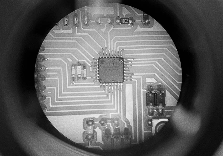
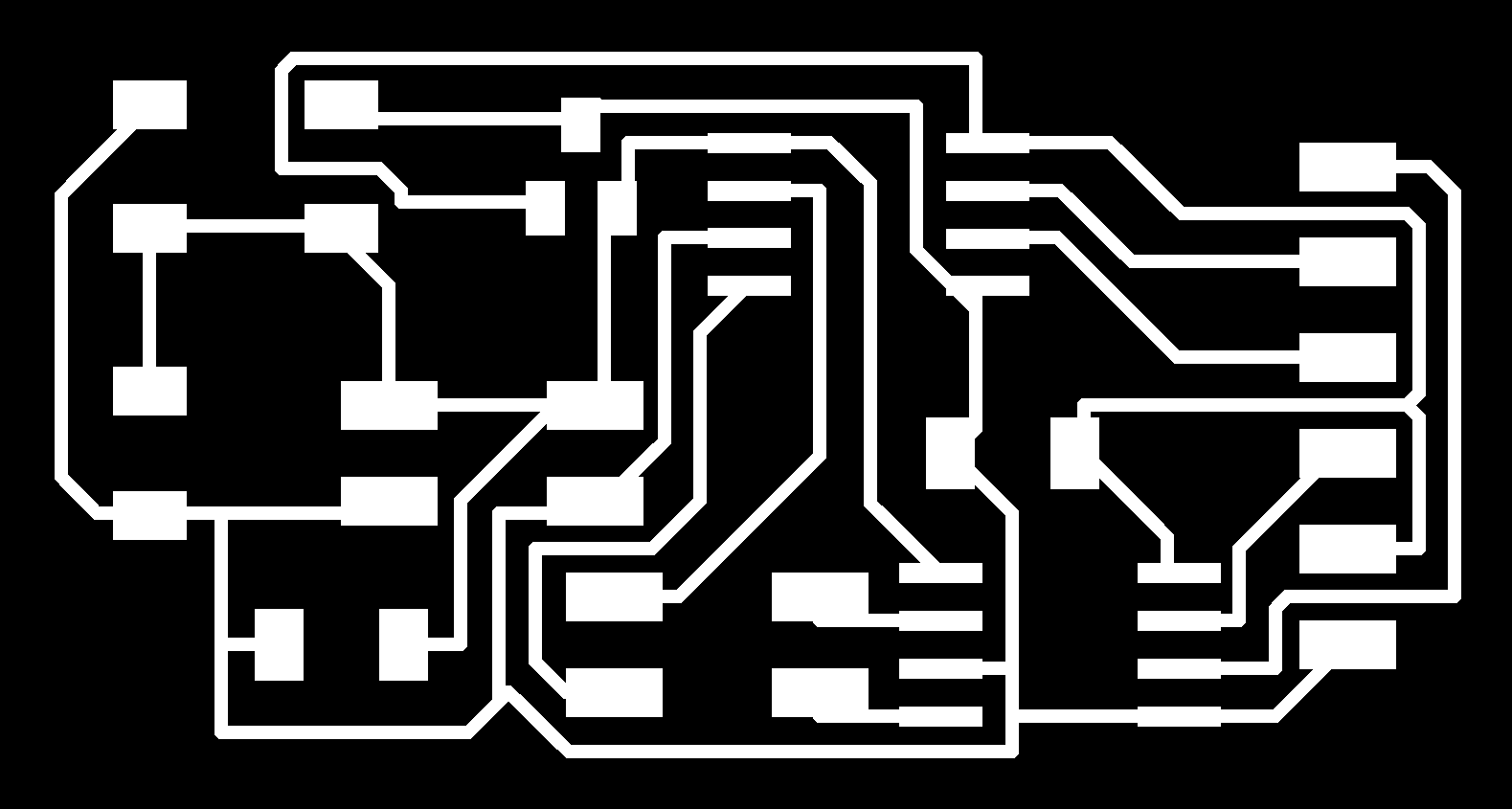
Board traces
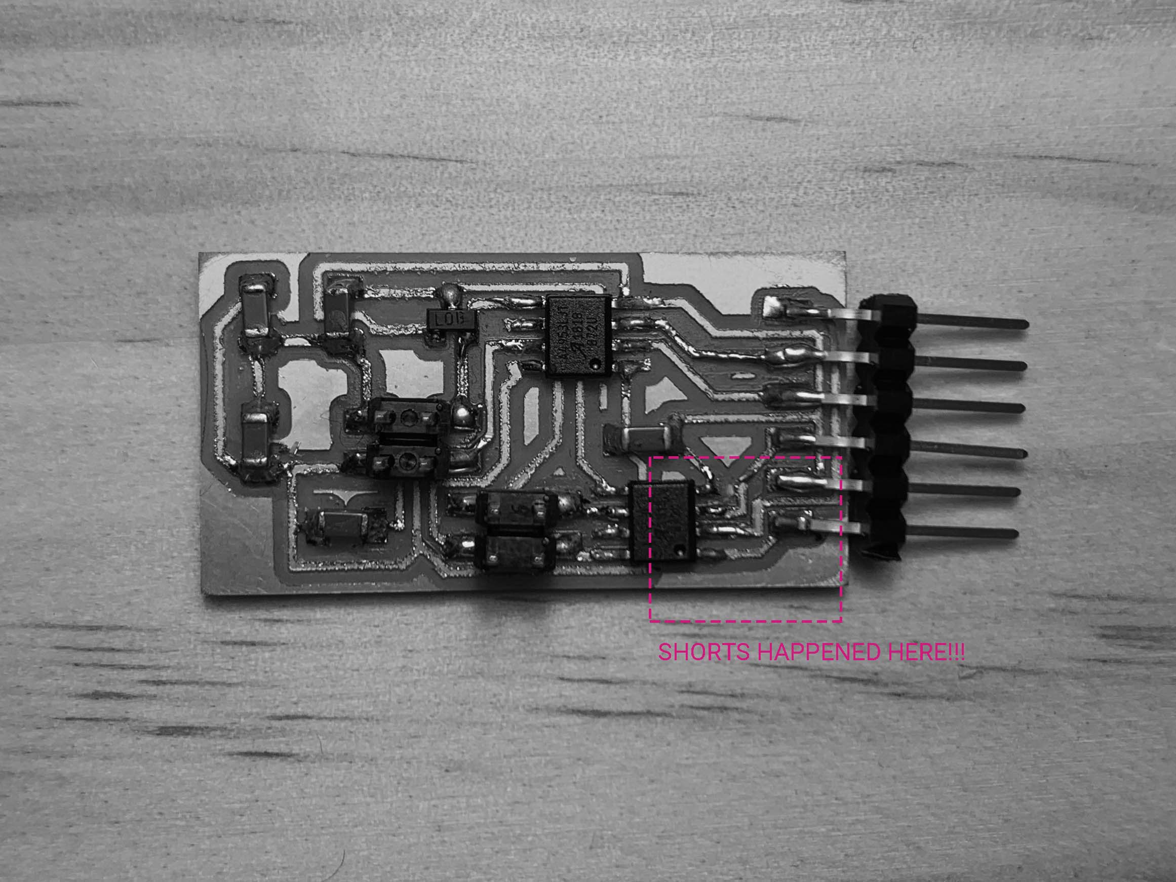
Another nightmare! Although my Fabduino board are able to read sensor data and blink code
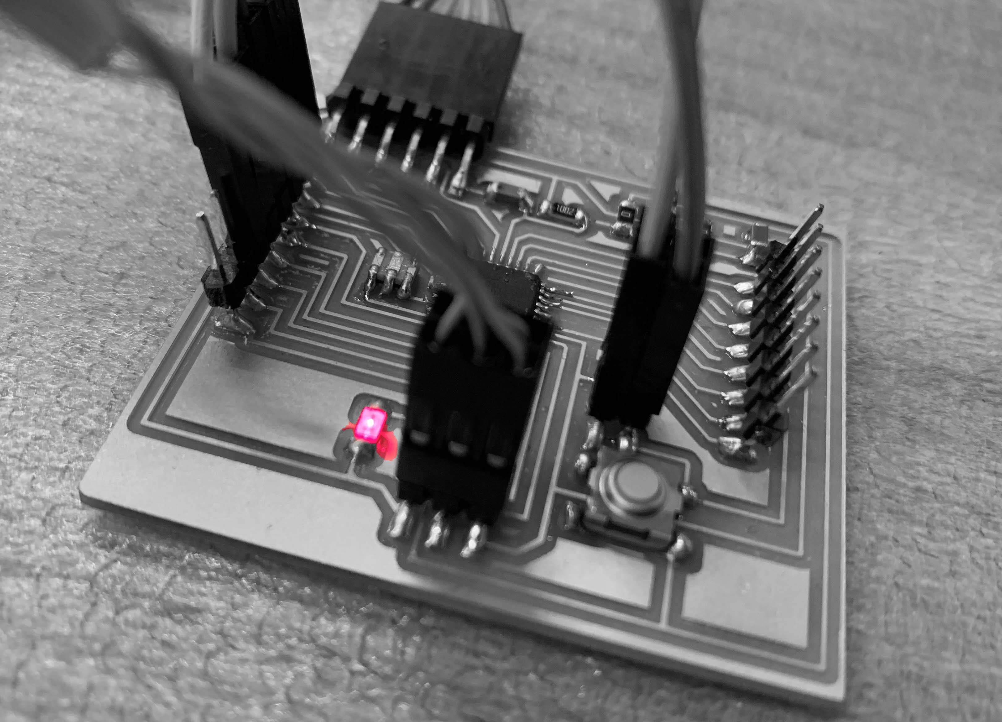
the bipolar motor got really hot and burns once its VCC and GND connected to the Fabduino.(This indicated a shorts) Anthony helped me check my schematic and board and we found that there are shorts happened because there is a spot that the mill didn’t cut through.
Code
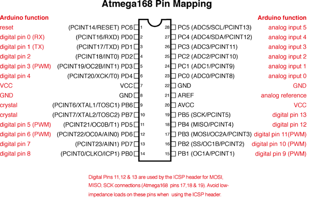
Something about pins:
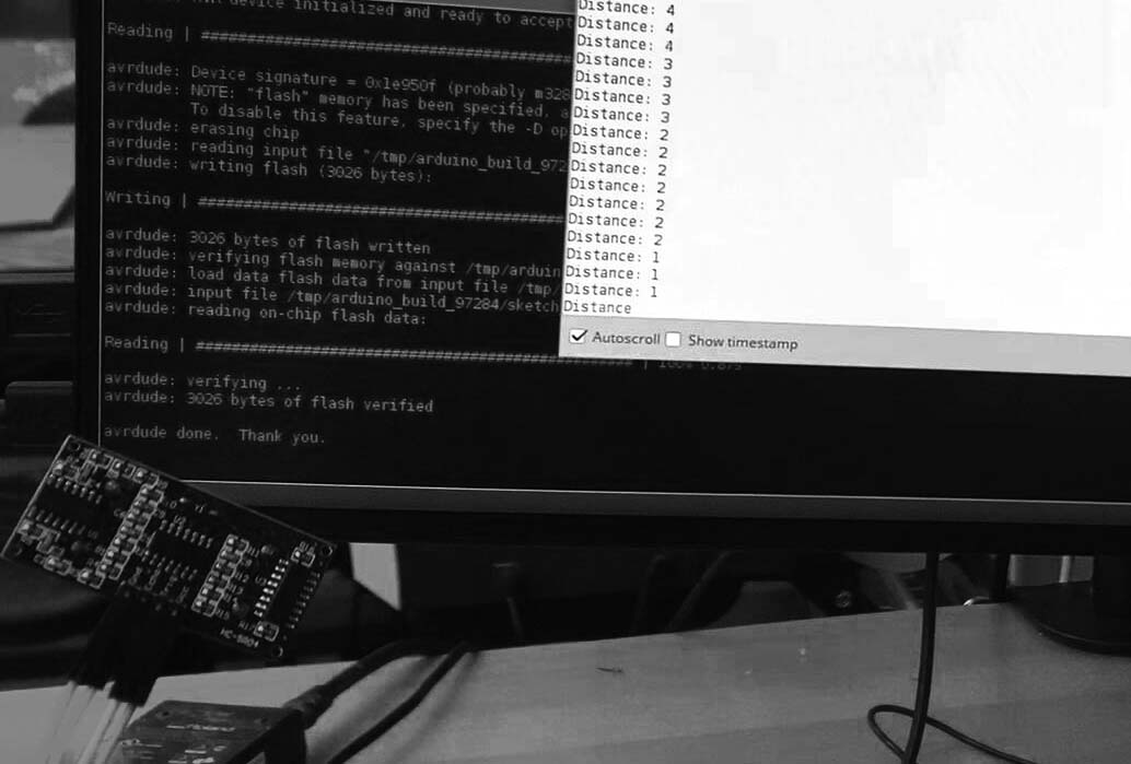
Finally, I got my input device talk to the output device.
Material used in this section
| Item | Supplier Code | Supplier description | Quantity | Price | Total | Vendor |
|---|---|---|---|---|---|---|
| Ceramic capacitor - 0.1 uF | 399-4674-1-ND | CAP CERAMIC .1UF 250V X7R 1206- | 1 | 0.12 | 0.12 | Digi-Key |
| Ceramic capacitor - 1 uF | 399-4674-1-ND | CAP CERAMIC 1UF 250V X7R 1206- | 4 | 0.12 | 0.48 | Digi-Key |
| Ceramic capacitor - 10 uF | 399-4674-1-ND | CAP CERAMIC .1UF 250V X7R 1206- | 3 | 0.12 | 0.12 | Digi-Key |
| Ceramic resonator - 20 Mhz | XC1109CT-ND | CER RESONATOR 20.00MHZ SMD | 1 | 0.43 | 0.43 | Digi-Key |
| Header - 2x2 | 609-5161-1-ND | 6 Positions Header Connector 0.100" (2.54mm) Surface Mount | 1 | 0.60 | 0.60 | Digi-Key |
| Header - 40x1 | S1011EC-40-ND | TH male header 0.1" (40pos) | 1 | 0.65 | 0.65 | Digi-Key |
| LED - red | 160-1167-1-ND | LED RED CLEAR 1206 SMD- | 1 | 0.13 | 0.13 | Digi-Key |
| Microcontroller - ATmega328p | ATMEGA328P-AU-ND | IC MCU 8BIT 32KB FLASH 32TQFP | 1 | 2.87 | 2.87 | Digi-Key |
| Resistor - 0 ohm | 311-0.0ERCT-ND | RES 0.0 OHM 1-4W 5% 1206 SMD- | 3 | 0.00 | 0.00 | Digi-Key |
| Resistor - 10k ohm | 311-10.0KFRCT-ND | RES 10.0K OHM 1-4W 1% 1206 SMD | 1 | 0.01 | 0.01 | Digi-Key |
| Resistor - 1k ohm | 311-1.0KERCT-ND | RES 1.00K OHM 1-4W 1% 1206 SMD- | 1 | 0.01 | 0.01 | Digi-Key |
| Tactile switch | SW262CT-ND | SWITCH TACT SMD W-GND 160GF | 1 | 0.74 | 0.74 | Digi-Key |
| H-Bridge A4953 | MC33039DR2GOSCT-ND | IC MOTOR DRIVER 5.5V-9V 8SOIC | 2 | 1.6 | 3.2 | Digi-Key |
| Regulator - 3.3V | LM3480IM3-3.3/NOPBCT-ND | IC 3.3V100MA LDO VREG SOT23- | 1 | 1.23 | 1.23 | Digi-Key |
At first, I hoped to use the mechanism of drawing machine to slide the curtain, but I soon realized the disadvantages of that design on the curtain system. Obviously, the movement of drawing machine on the plane depends on XY-Axis, so it has a boundary and limitation; that is, if you want to design a curved curtain system, then you must design the whole area of the curve path's bounding box. In the design of the curtain scale, it is very wasteful and inefficient. So I make some revision to the origin plan.
3D-printed carriage in the original design. The movement of the carriage depends on sliding on the rod.
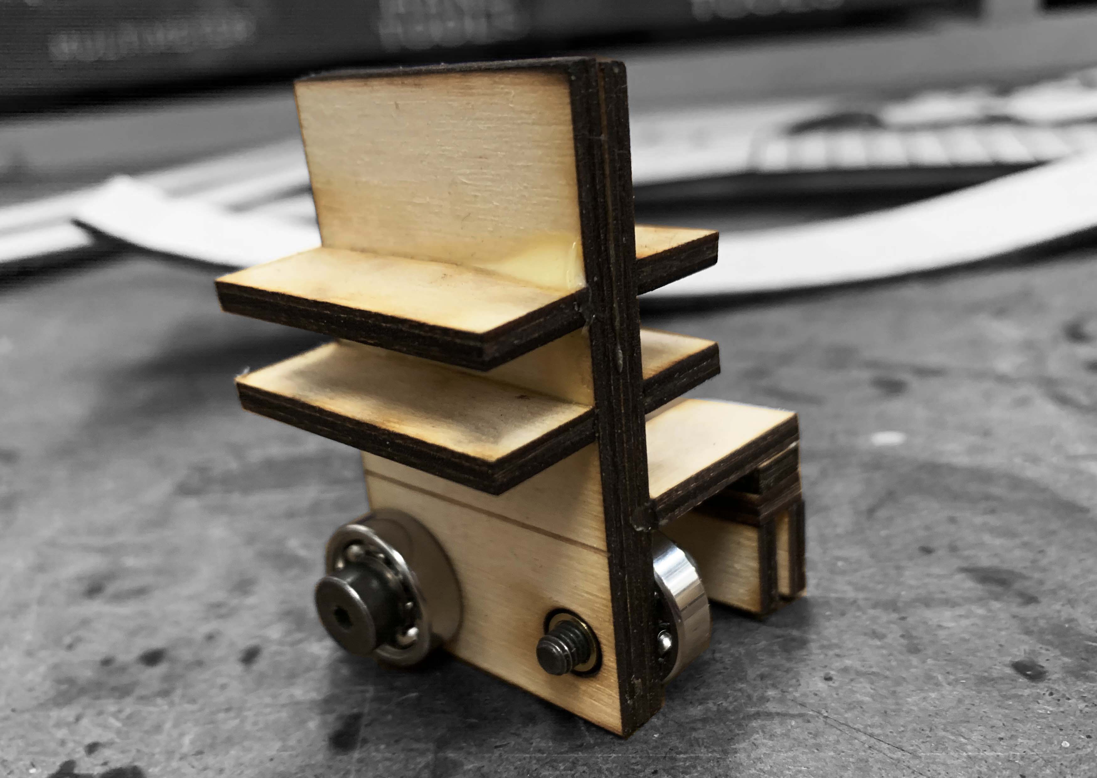
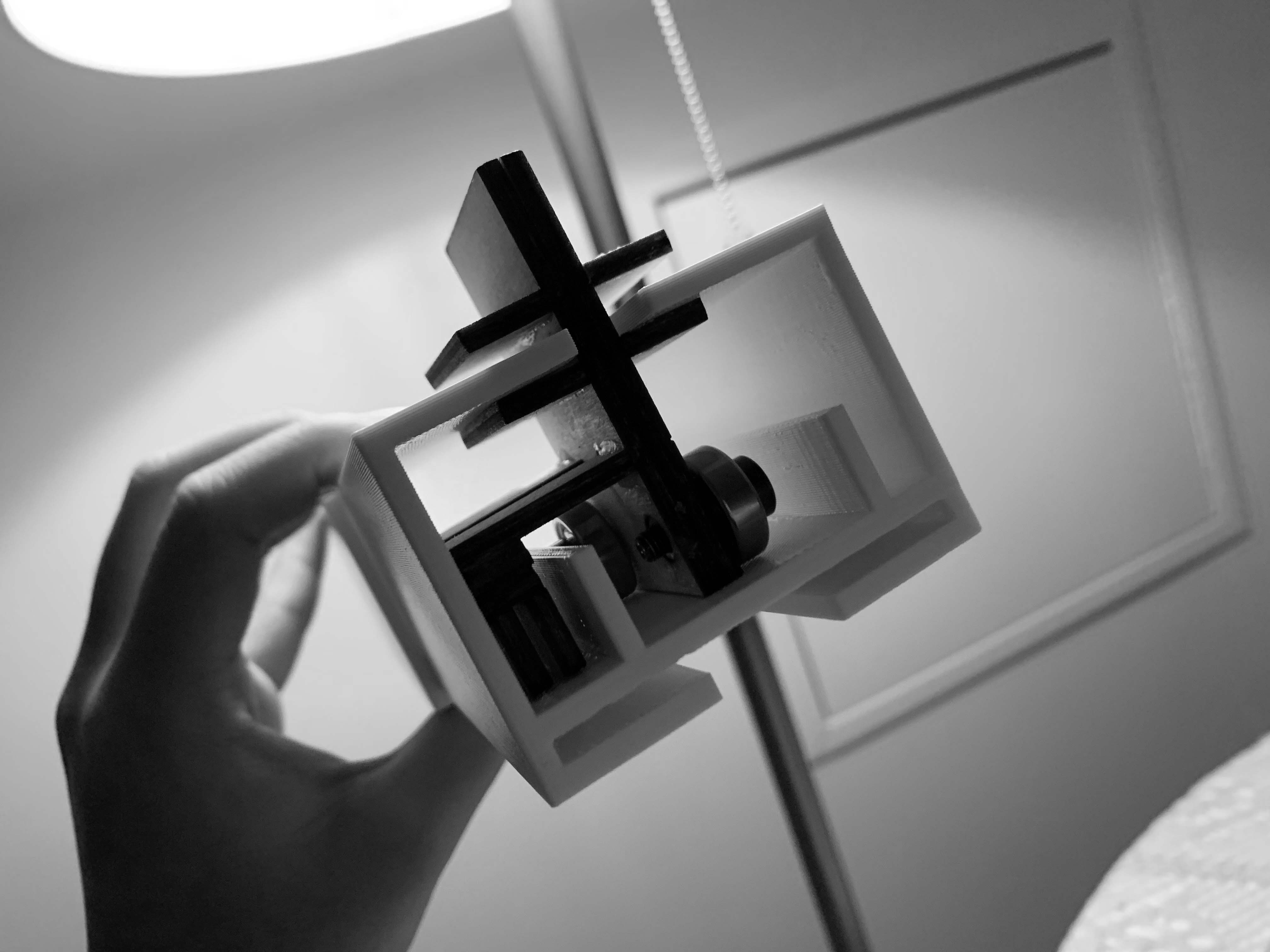
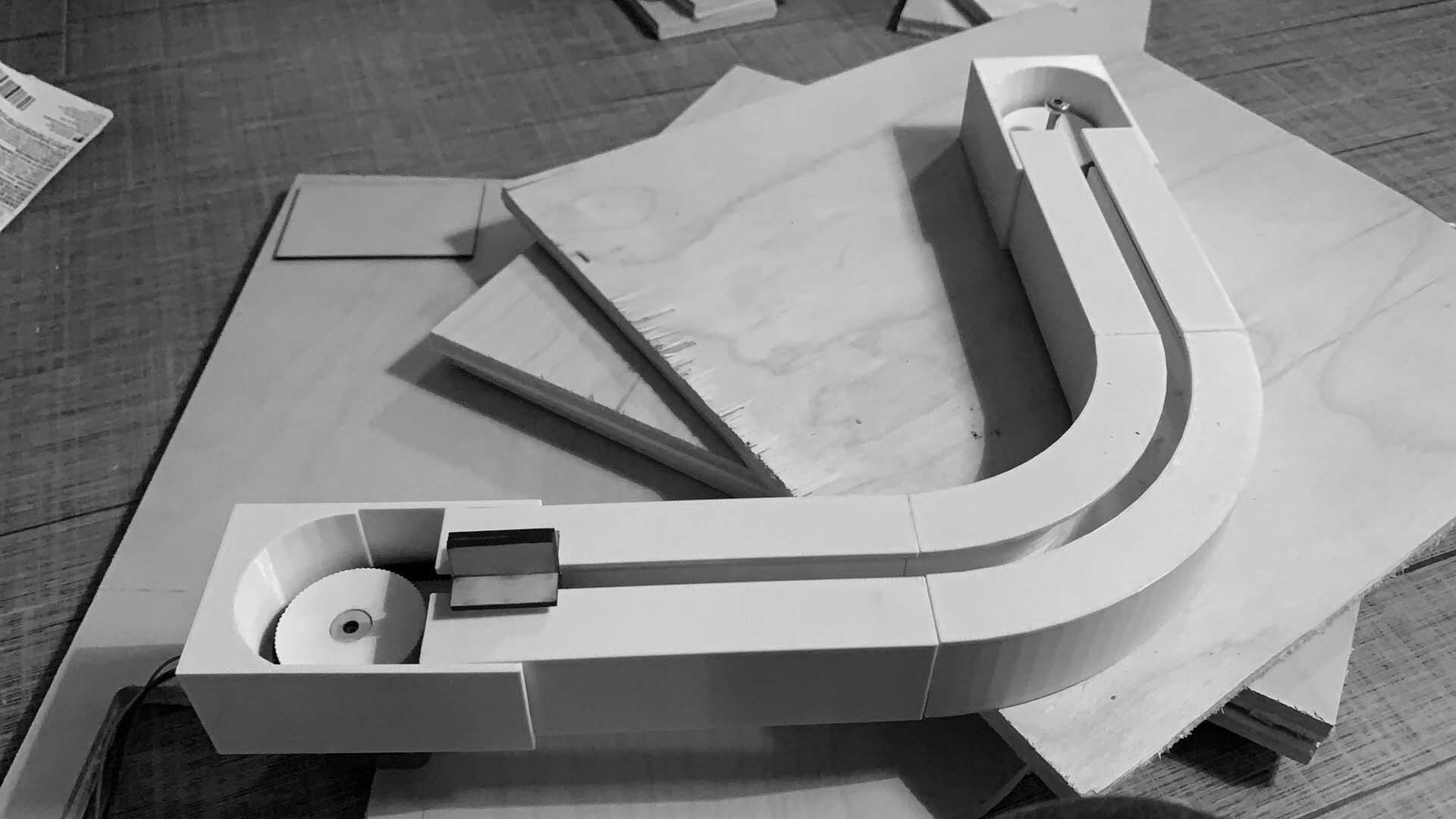
The revision design
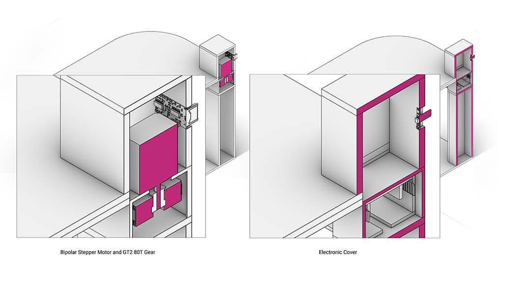
Three main components in this design are
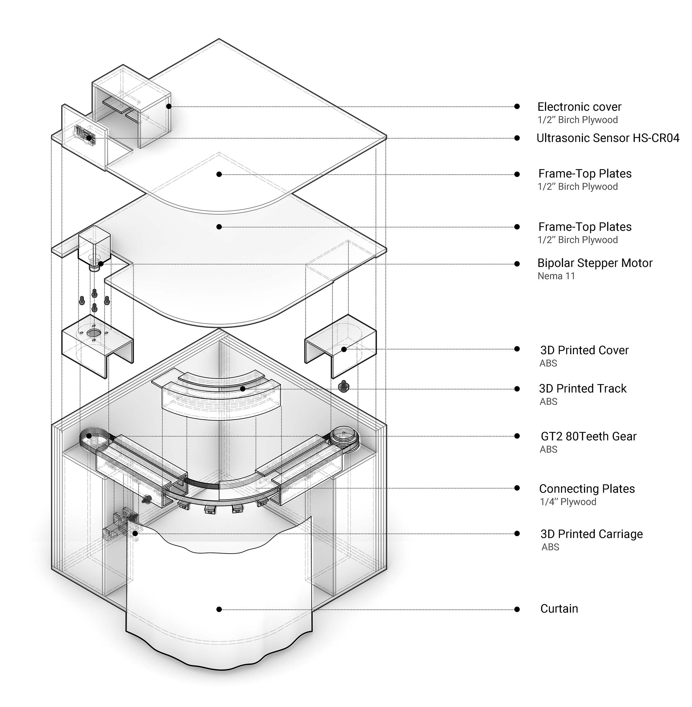
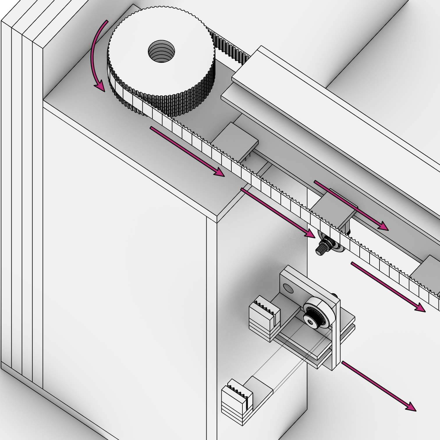
Movement Mechanism
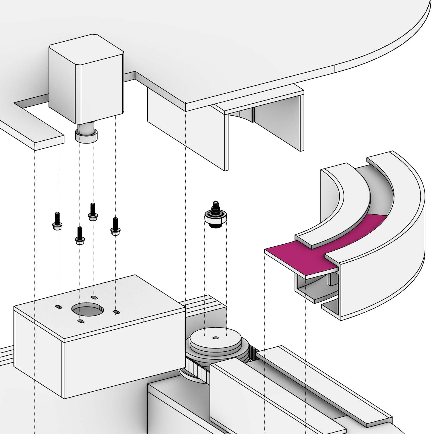
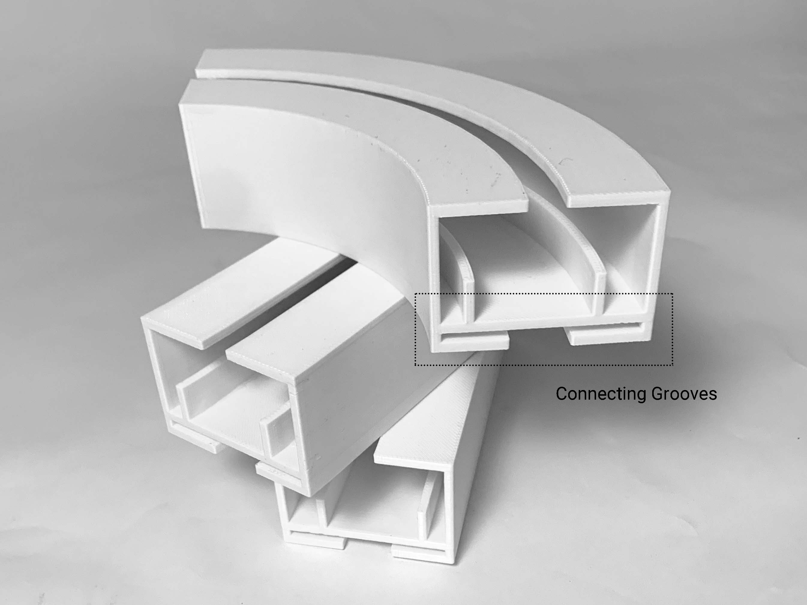
Connection
I think there are some regrets in this project so far. I spent a lot of time working on the communication between input and output devices. Although I learned a lot and understood methods that can communicate input and output, it really delayed my fabrication and design time. But overall, the working electronics and mechanism is a very good signal and gives me the confidence to continue the project.
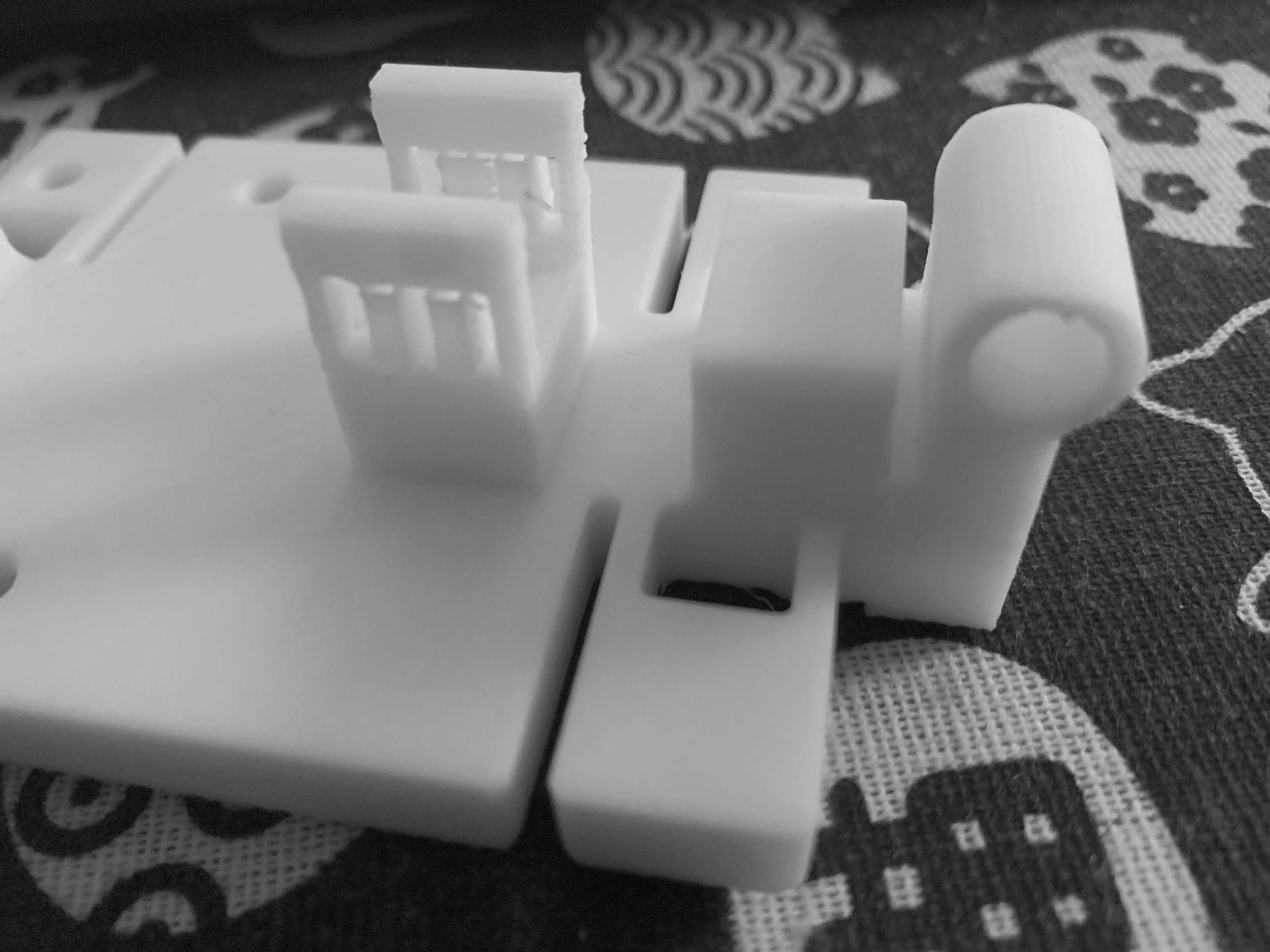
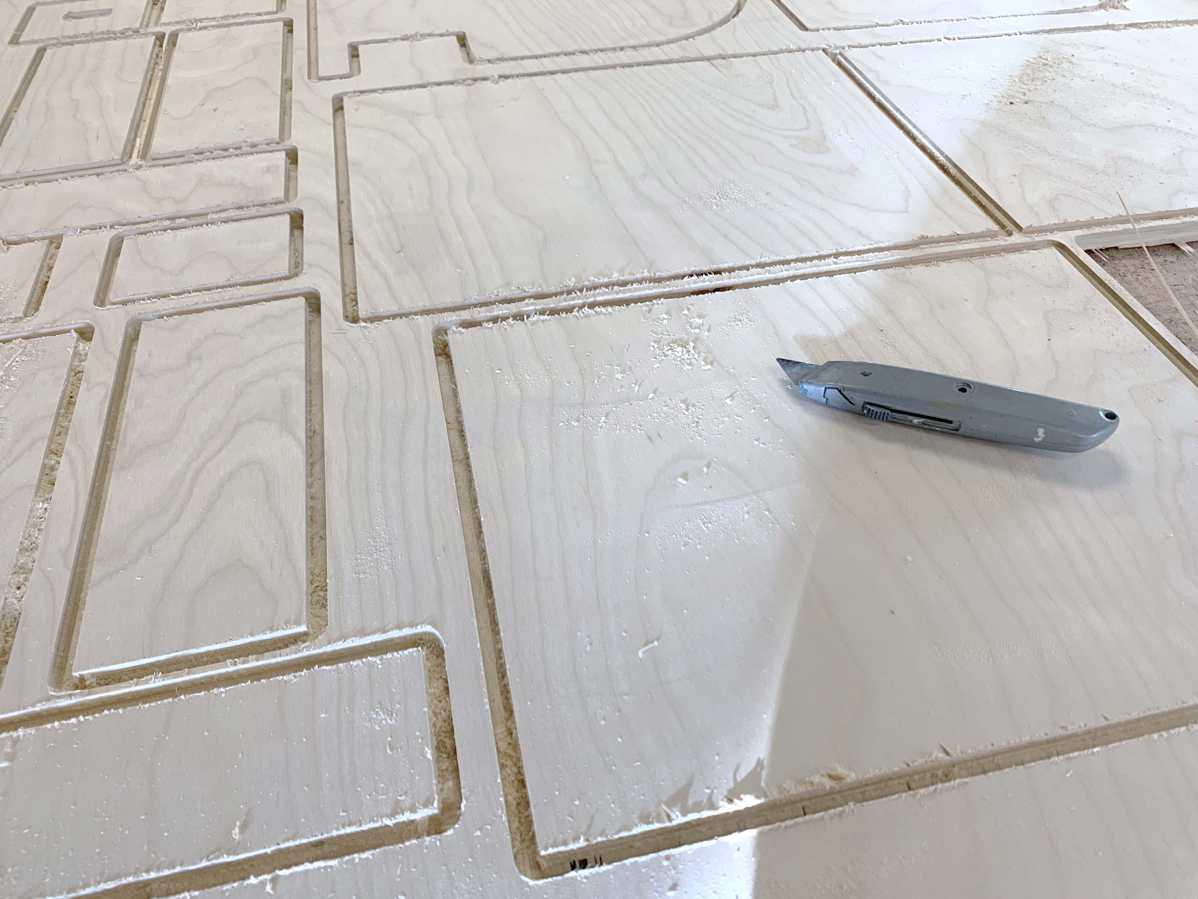
Simulation before fabrication
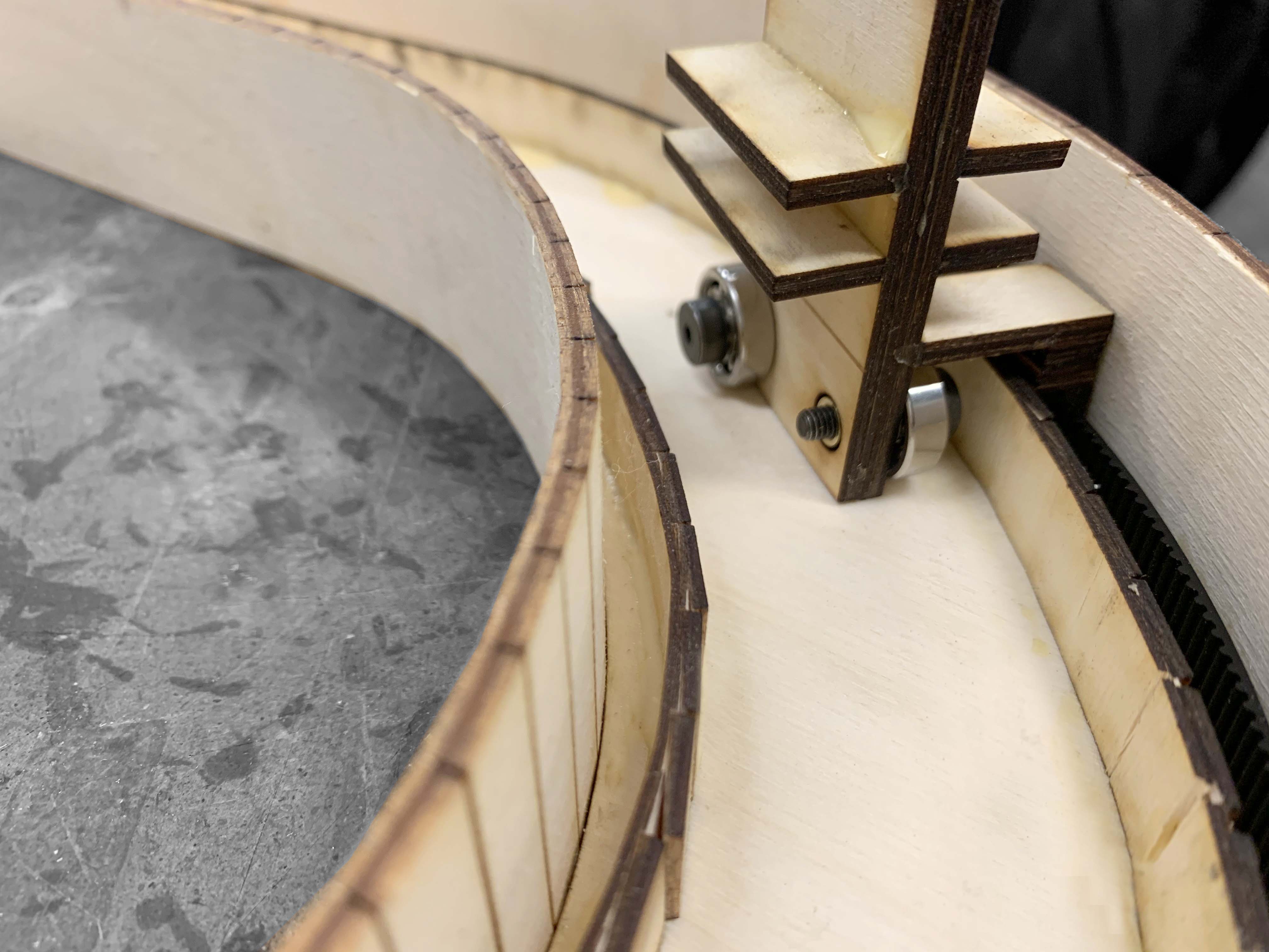
The carriage movement is a little bit glitchy because of the wood glue traces that I didn't clean well. To make sure the smooth movement, I think the best option is to 3D Print this track. However, the dimension of the carriage and curvature of the track work fine with this prototype.
Curtain accessories
Settings
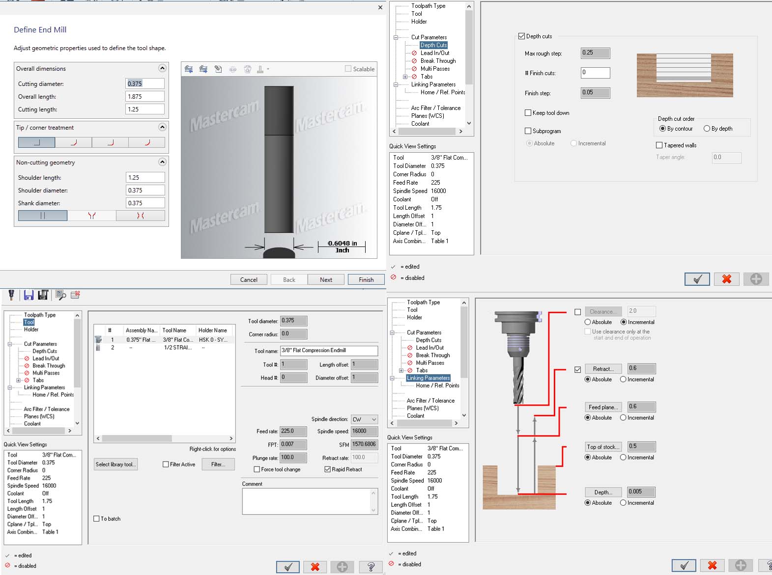
Onion Skin: 0.0050
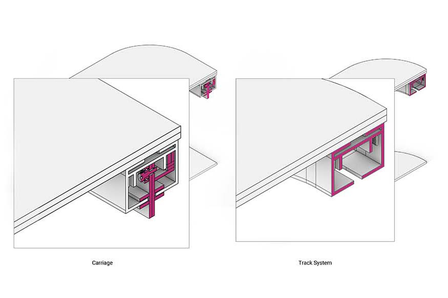
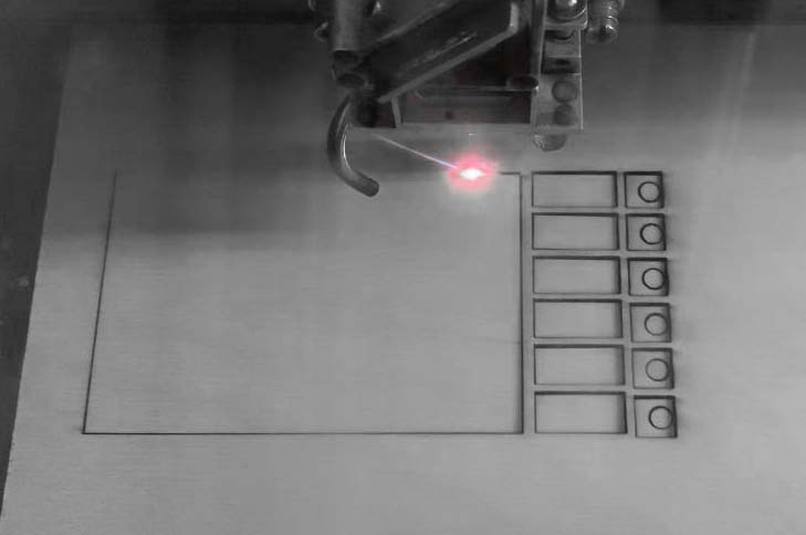
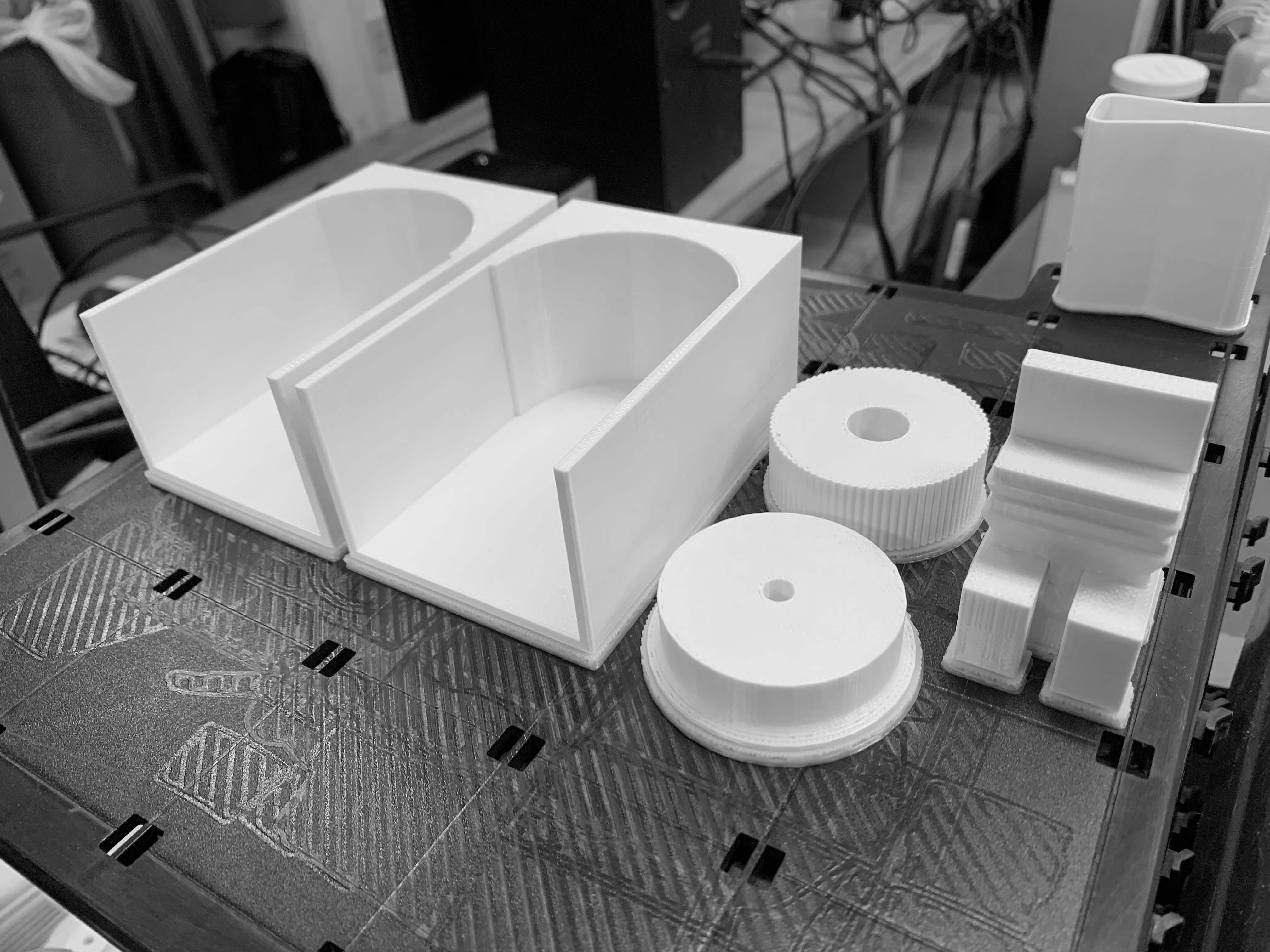
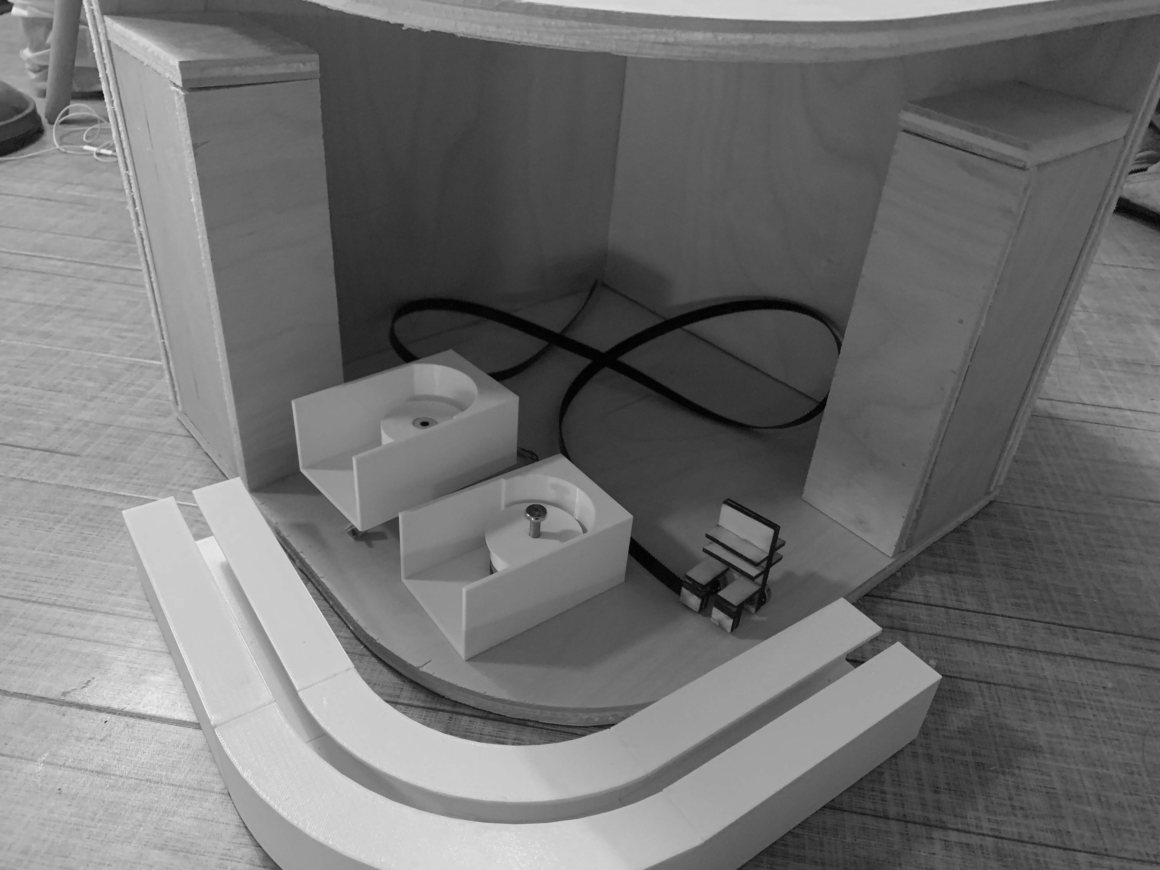
Carriage and Track
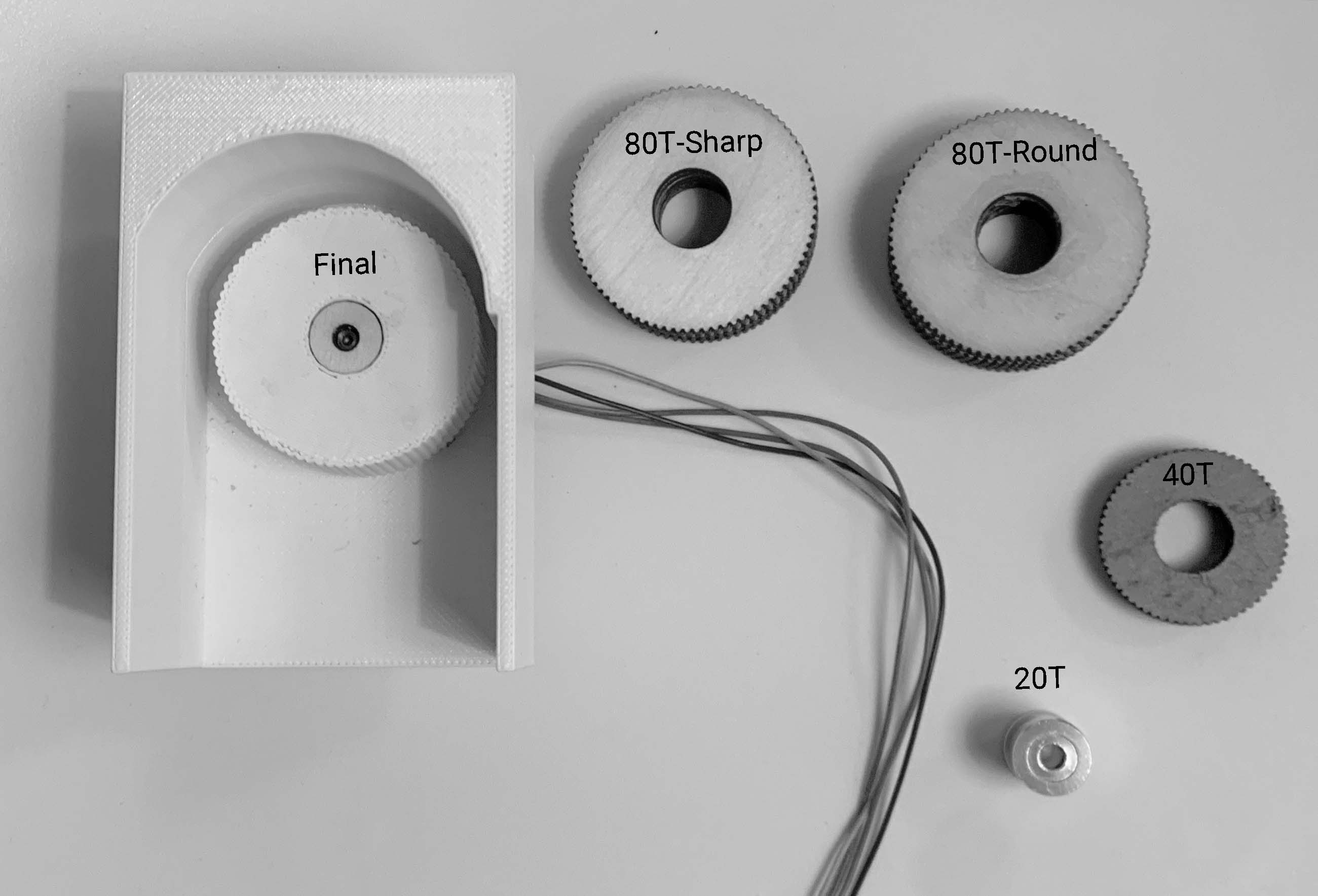
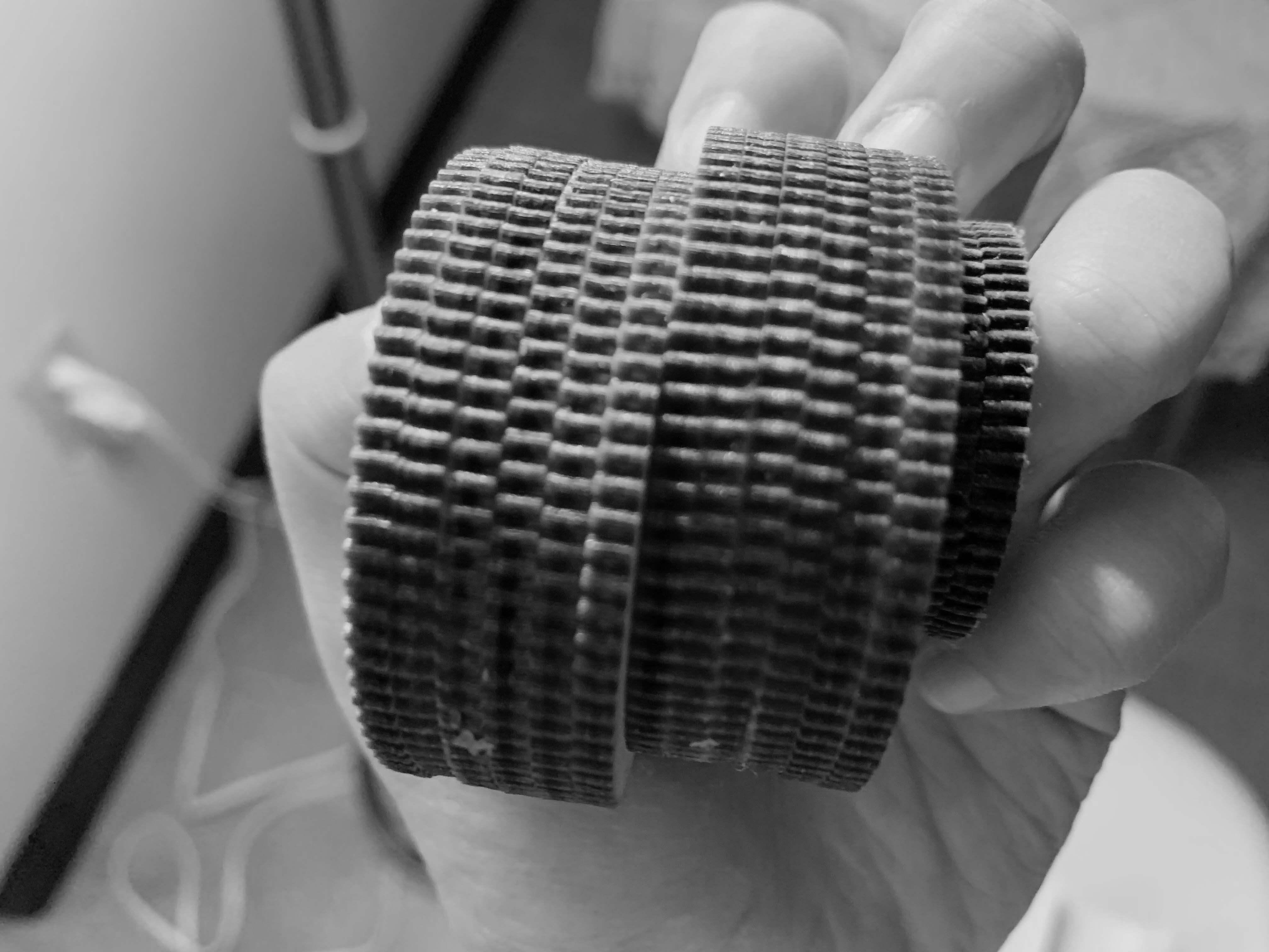
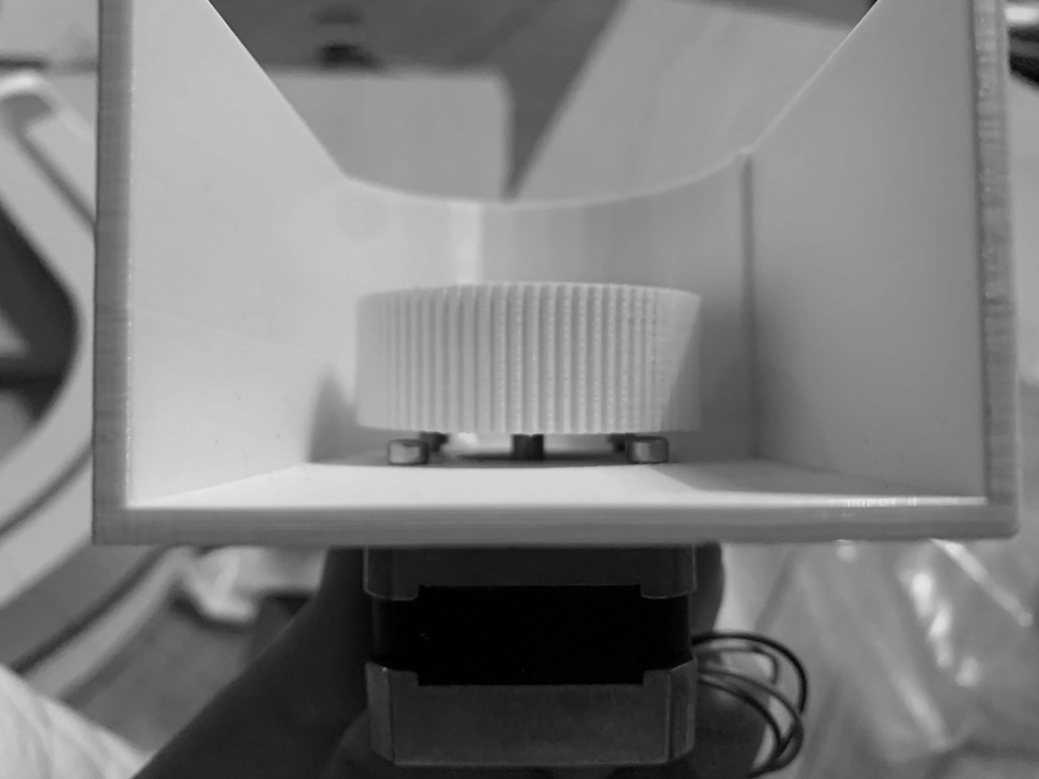
Motor and Gear
Track System
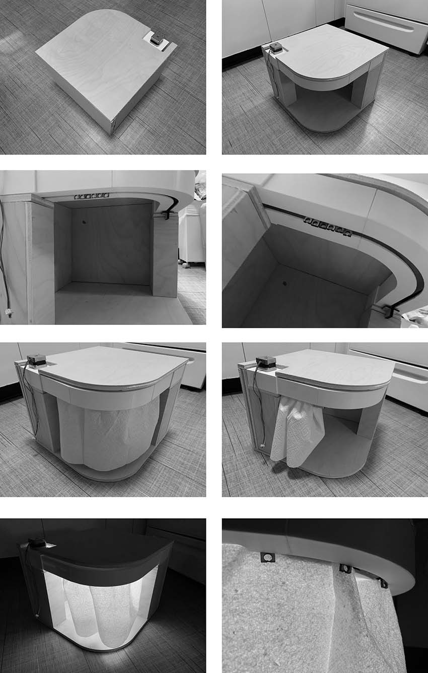
Housing
Final
Materials used in this section
| Item | Supplier Code | Supplier description | Quantity | Price | Total | Vendor |
|---|---|---|---|---|---|---|
| ABS | MWVCRU99 | ABS Filament | ~ | 19.99 | ~ | Fab Inventory |
| M3 SHCS | 91292A113 | Motor Mounting | 4 | 19.99 | ~ | McMaster |
| Heat-Set Tapered Insert | 94180A331 | Mechanical Design w/ Plastic | 2 | 19.99 | ~ | McMaster |
| M3 SHCS | 91292A113 | Motor Mounting | 4 | 19.99 | ~ | McMaster |
| 625ZZ Bearings | 6153K113 | Rollers, Idler | 3 | 19.99 | ~ | McMaster |
| 10mm (or 9mm) Wide GT2 Belt | PU-B10mm-5 | Find Steel-Core for Stiffness | 5m | 14.12 | 14.12 | Amazon or SDP/SI |
| Bearing Shims | 98089A331 | 5x10x0.5mm | 4 | 2.49 | 2.49 | Amazon or SDP/SI |
| 20T or 16T GT2 Pulley | 20TW10 | 10mm or Wider, 5mm Bore | 1 | 2.49 | 2.49 | Amazon or SDP/SI |
| 1/2'' Birch Plywood | ~ | 48''X48'' | 1 | 15 | 15 | MIT N51 |
| 1/4'' Birch Plywood | ~ | 24''X30'' | 1 | 7 | 7 | MIT N51 |
Workflow Conclusion
What parts and systems were made and what processes were used?