Final Project
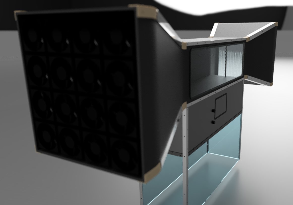
As a final project I want to make my own tiny Smoke Wind Tunnel. I consider it’s a really cool and fun device. It is so complex to have accurate results but it has a huge educational value. To see streamlines with your eyes is something unusual!
/////////////////////////////////////////////////////
The main theoretical estimations are stream flow calculations based on Bernoulli and Continuity equations. A wind tunnel is just a composition of a Diffuser and a Nozzle joined by a fixed diameter pipe.
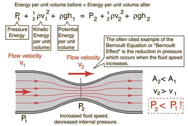
Continuity equation gives us the following equation:
What it is looking for is to have as much velocity as possible inside the duct (v2) but also being realistic. We want to put stuff inside so it has to be not so tiny so we can watch it better and design mockups in a big scale to be as detaillist as possible!
To start to make tangible this idea, let’s start to dimensionalize it with stuff I’ve founded in the lab.
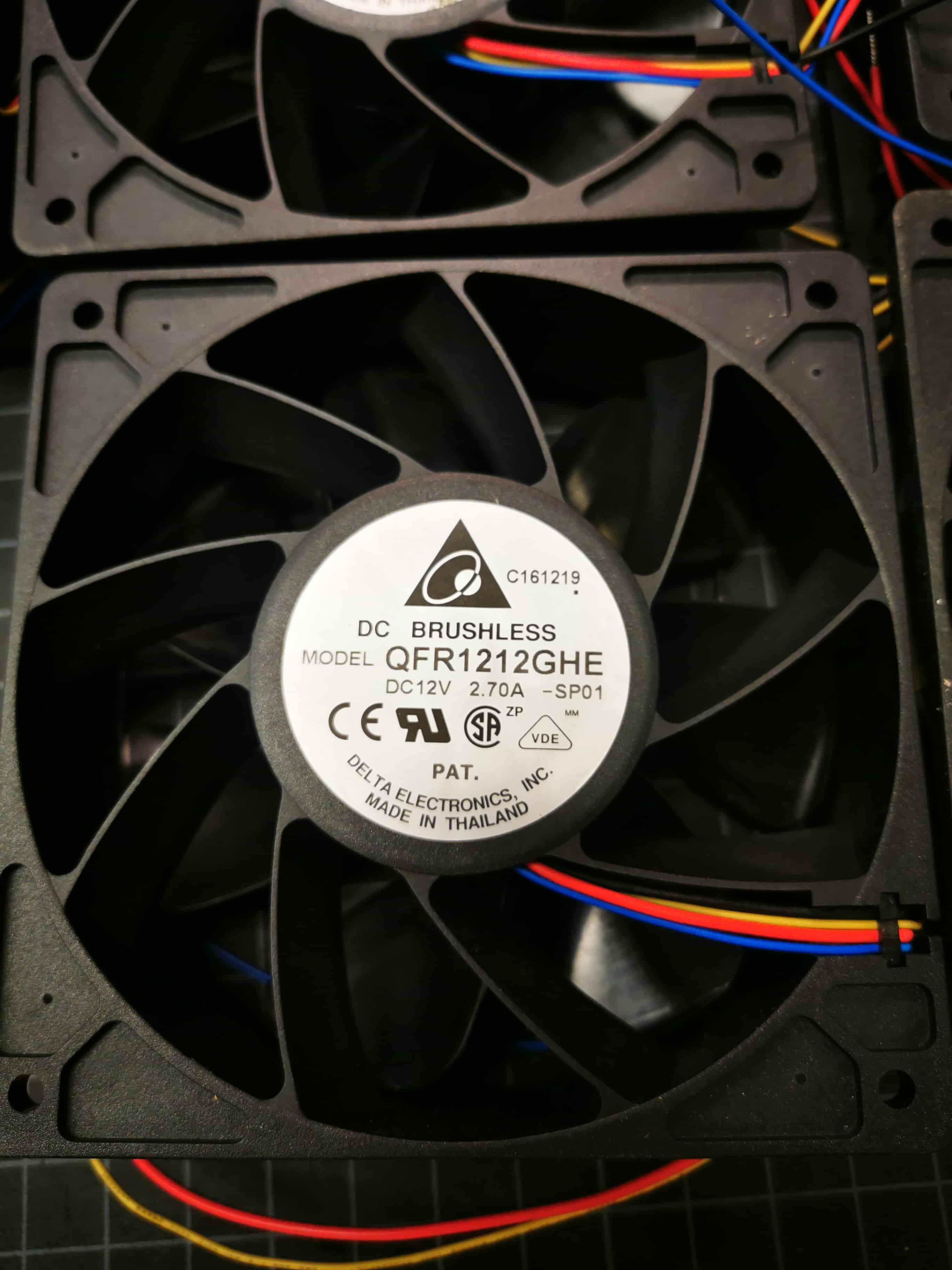
I took a box with 12 of the above dc brushless computer fans model QFR1212GHE SP-01. I decided that the suction plant of the wind tunnel will be composed by a 4x4 array of those guys. Looking the provider specifications, I’ve found that :
As the Air Flow is 2.89 m3/min, doing the following calculations, we can estimate the linear velocity of a square based area of the dimension of the fan (120mm x 120mm). This velocity calculation is extremely important in order to calculate the final velocity of the test area.
Each fan is giving us 2.89 m3/min. To estimate velocity through area we can use the mass flow equations.
Now to estimate linear velocity based in a desired area (due to my final are of suction will be a composition of square units of area, lets assume that the air are which we are expulsing air is the square area of the fan which is 120 mm * 120 mm (0.0144m2).
With this design input, assuming we are going to use an array of 4 x 4, giving some mm as gap, the wider length of the diffuser and nozzle will be 550mm.
Its is gonna be estimated the duct section based on the maximum velocity we can reach in it. Ideally it could be 80km/h (aprox 22m/s) :
In order to make it easier to manufacture, Its been set that each side will be 300mm. The design process, once estimated the distances, has follow those sketches.
Pase 1_ Whiteboard Sketch
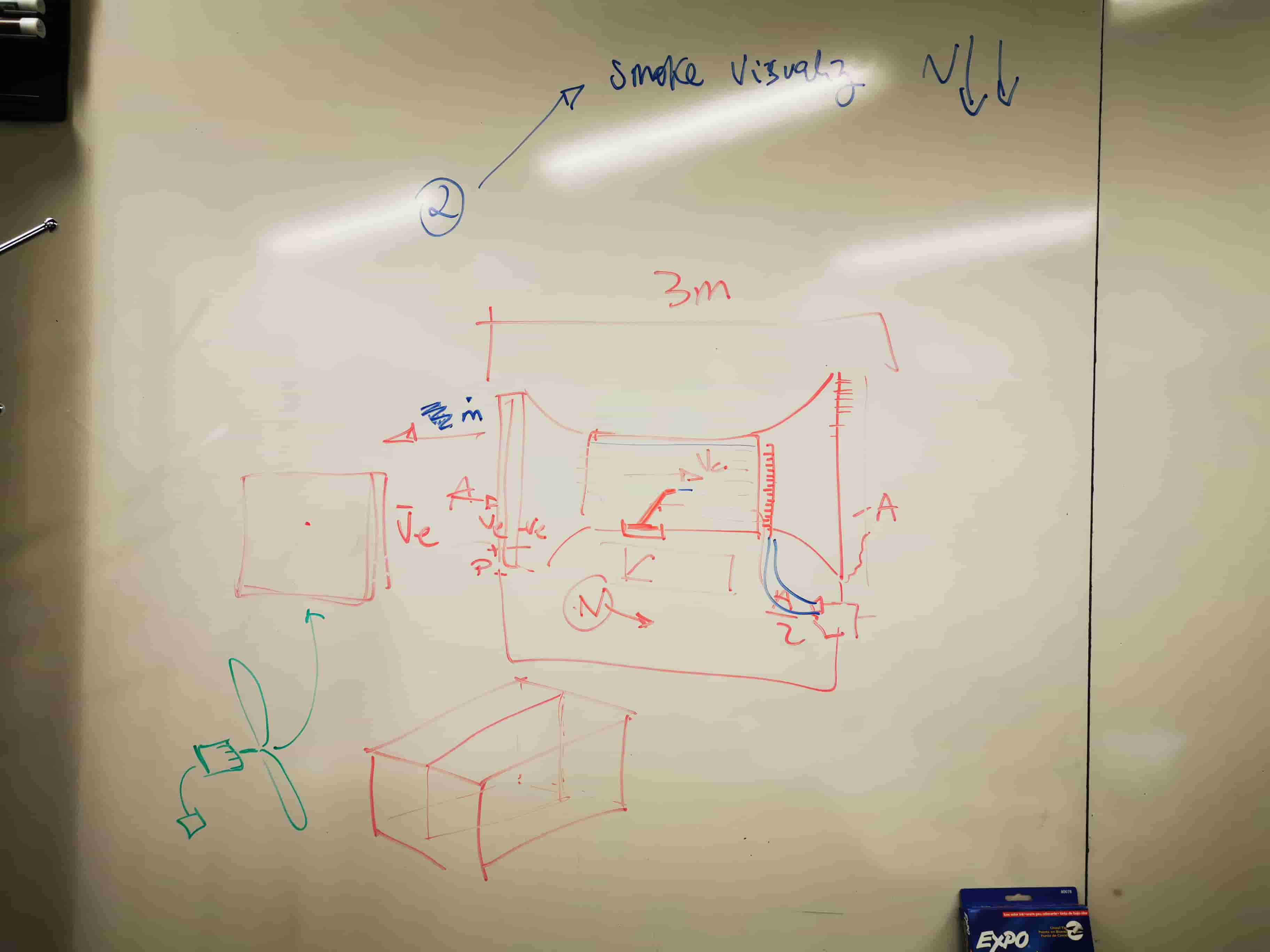
Phase 2_ A little more detailed sketch with some new ideas
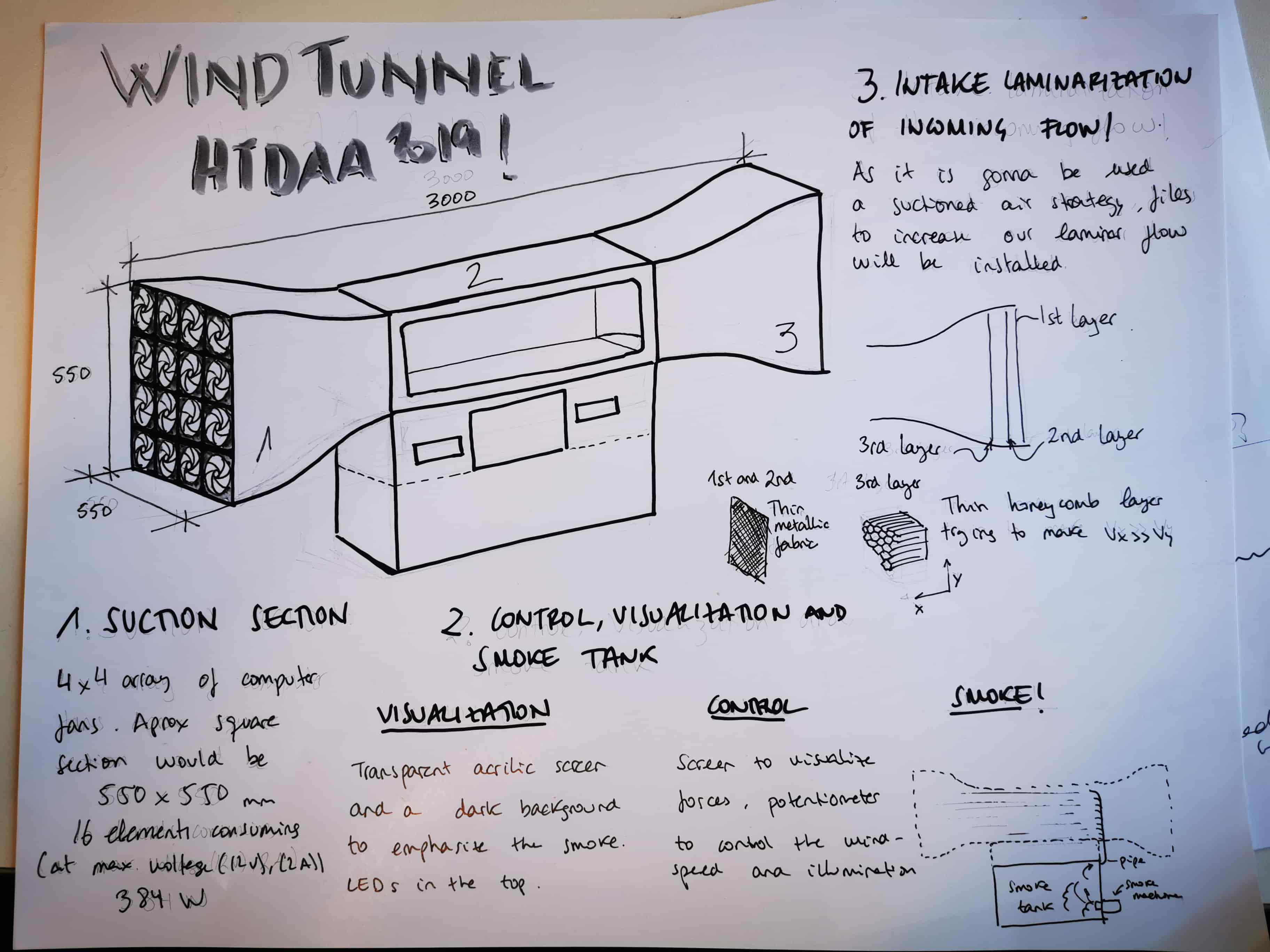
As it can be seen, it is composed by 3 main stages.
1_The Air ducts, composed by a nozzle, a diffuser and a fixed pipe in which experiments will take place.
2_Control. Zone in which we will be able to control the velocity of the air as well as (hopefully) has some control item to measure and display aerodynamic forces of the item to test.
3_Smoke container. Composed by the smoke machine, which will feed this container with smoke and a small pipe with which will displace smoke in a longitudinal array inside the duct.
Phase_3. Time to CAD!
After so so many years using Catia (close to 8 years…..) my actual situation has forced me to change CAD tool! I decided to use Fusion instead FreeCad due to the CAM feature it has. I’ve seen some limitations compared with Catia but it has been fun to change and adapt to a different SW.
As a first attempt, I designed the nozzles and diffuser optimized for a better air behavior.
As bigger radius the better. But this design led us to a problem! It is not trivial to manufacture in a fast way with a 3 axis CNC miller from a flat perform those shapes. And the most critical part is not to generate them (living hinges would work!) Is to find a metallic profile for the edges with this shape.
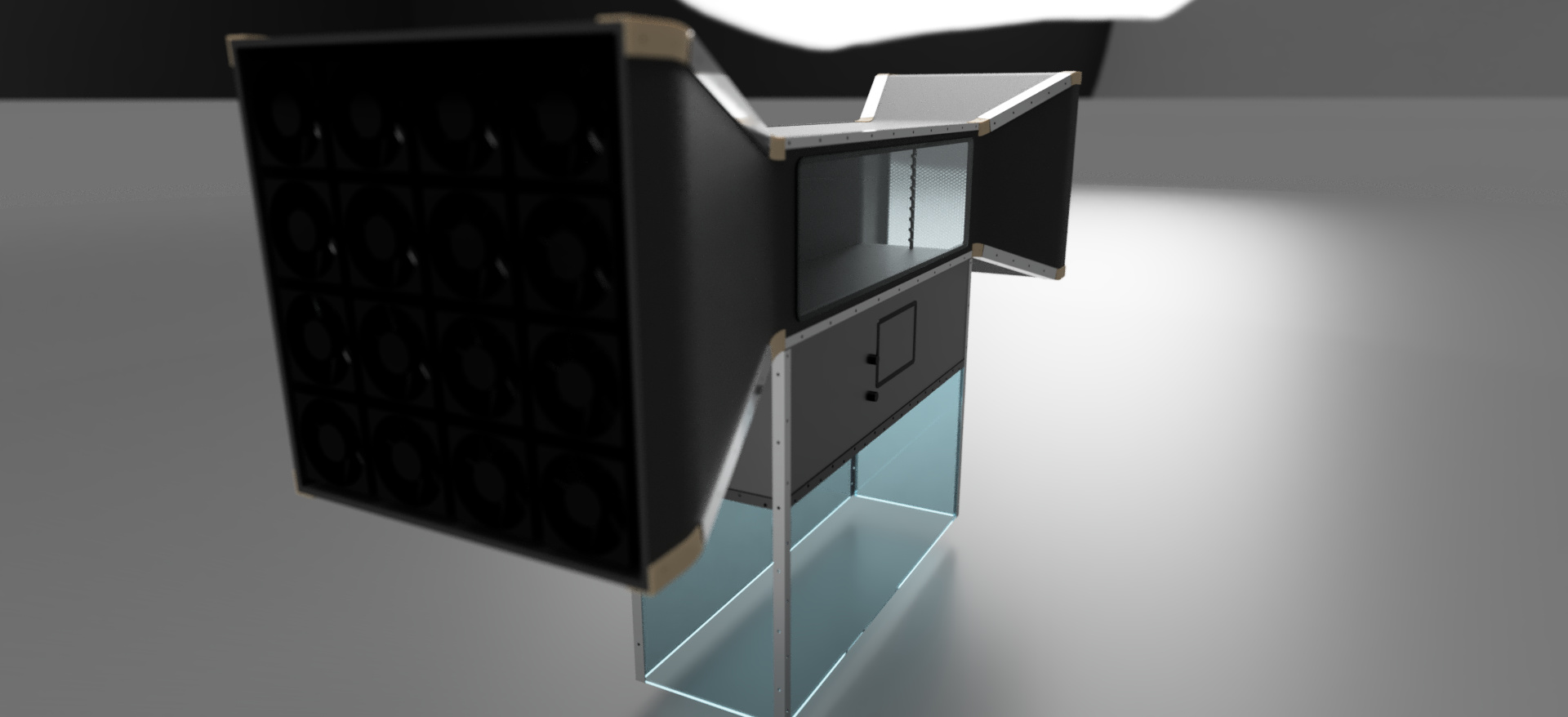
For that reason, it has been redesigned to this geometry. This is the actual version of the wind tunnel! After a session of detail CAD, this is the final model that has been decided to manufacture:
Also, those are the final renders that fusion has done. Hope you like it!

This week we were encouraged to mill and make something significantly big. I want to use this week to advance in my final project. Let start thinking in the windtunnel! Im going to manufacture the Nozzle, the Diffuser and the duct.
When I was designing the windtunnel, the first design I made for the intakes were all curvy, great for the air behavior, horrible for manufacturing (at least with my knowledge in wood)
BUT
Last week I spent some time with Airbus colleagues and after seing my secon version (great for manufacturing, not great for air) they encouraged me on manufacture the first design proposal.
I guess this class (and MIT in general) is the place to go out your conformt and try to do something you dont have the knowledge to. Lets learn doing it!
I ordered some 6mm thickness plywood. I didnt want to go to halph of an inch. It could be so difficult to bend and the structure wont hold that much load.
Manufacturing and assembly of the duct seems pretty straight forward. Lets start with the design and manufacturing of the intakes. Im gonna take this 1 curvature shape, unfold it in Rhinoceros, take the plant 2d shape, mill it in a 6mm
My challenge no is: How can I bend plywood and how can I join them externally in a smart/clean way?
As a first step rastering for information, I posted a detailled issue in the class site Gitlab. All the people who responded me were so so so helpfull. What a long messages full of information
MIT Hobby Shop offers a huge variety of wood tools. One response of my git issue told me that for steam bending wood, that was the right place to do. And I did. The moulds I designed for this first strategy were the following
The problem of this first strategy is that the Hobby Shop asked me for a fee and It was going to be impossible to do it before wednesday.
Changing the strategy
At this point, I was forced to change strategy. I decided to bend the plywood with living hinges and shape it makking a wood framework, using OSB as a mould frame able to deform the 4 sheets to take them to their position.
I started after design them, to mill them. When finishing the first job, because a non precise allignment in the XY axis and also because don't giving the propper atention to the screws I used to fix the wood in the table, I broke an endmill..
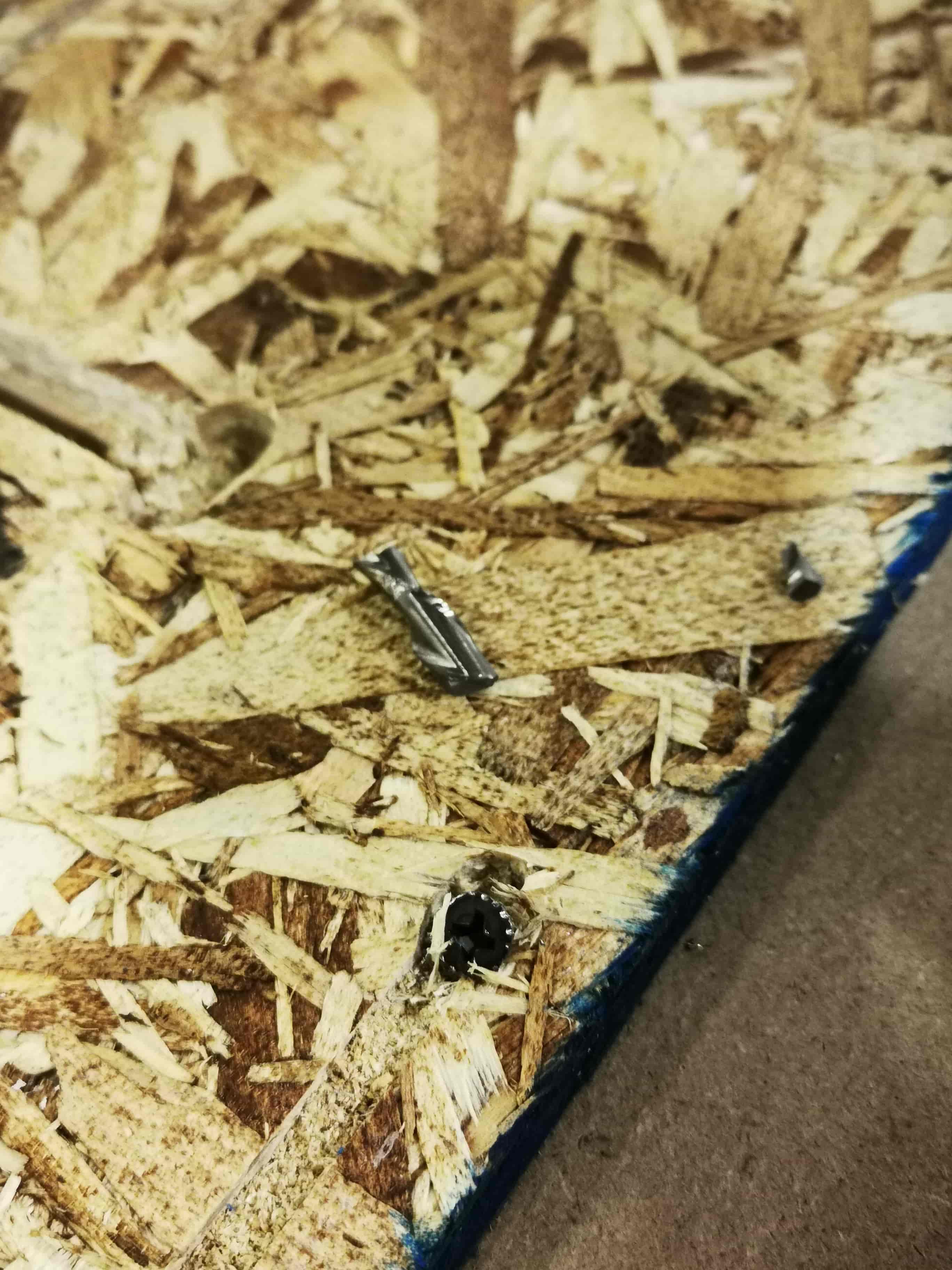
Despite this incident, all the milling process went perfect and all the pieces were done without any problem.
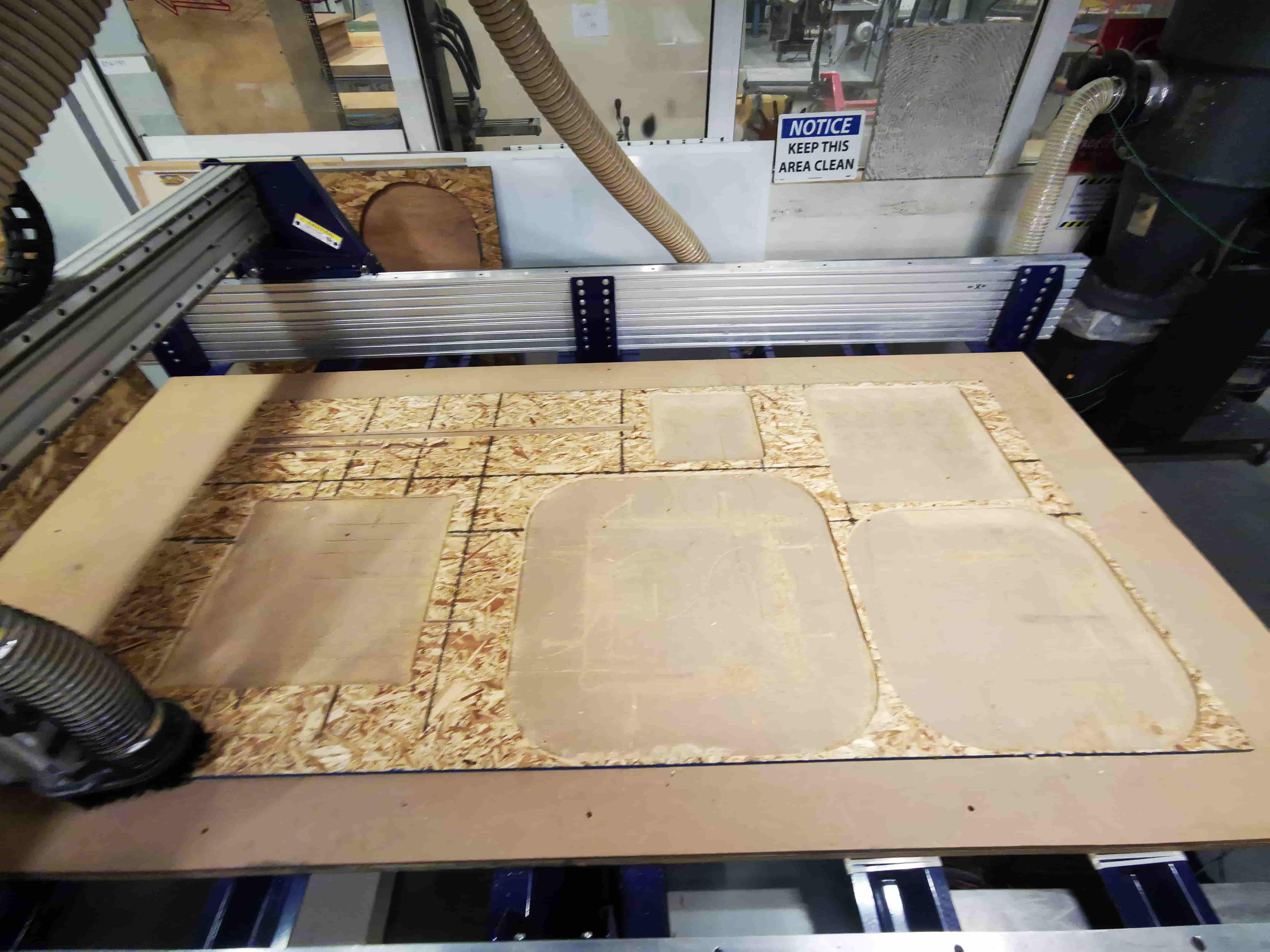
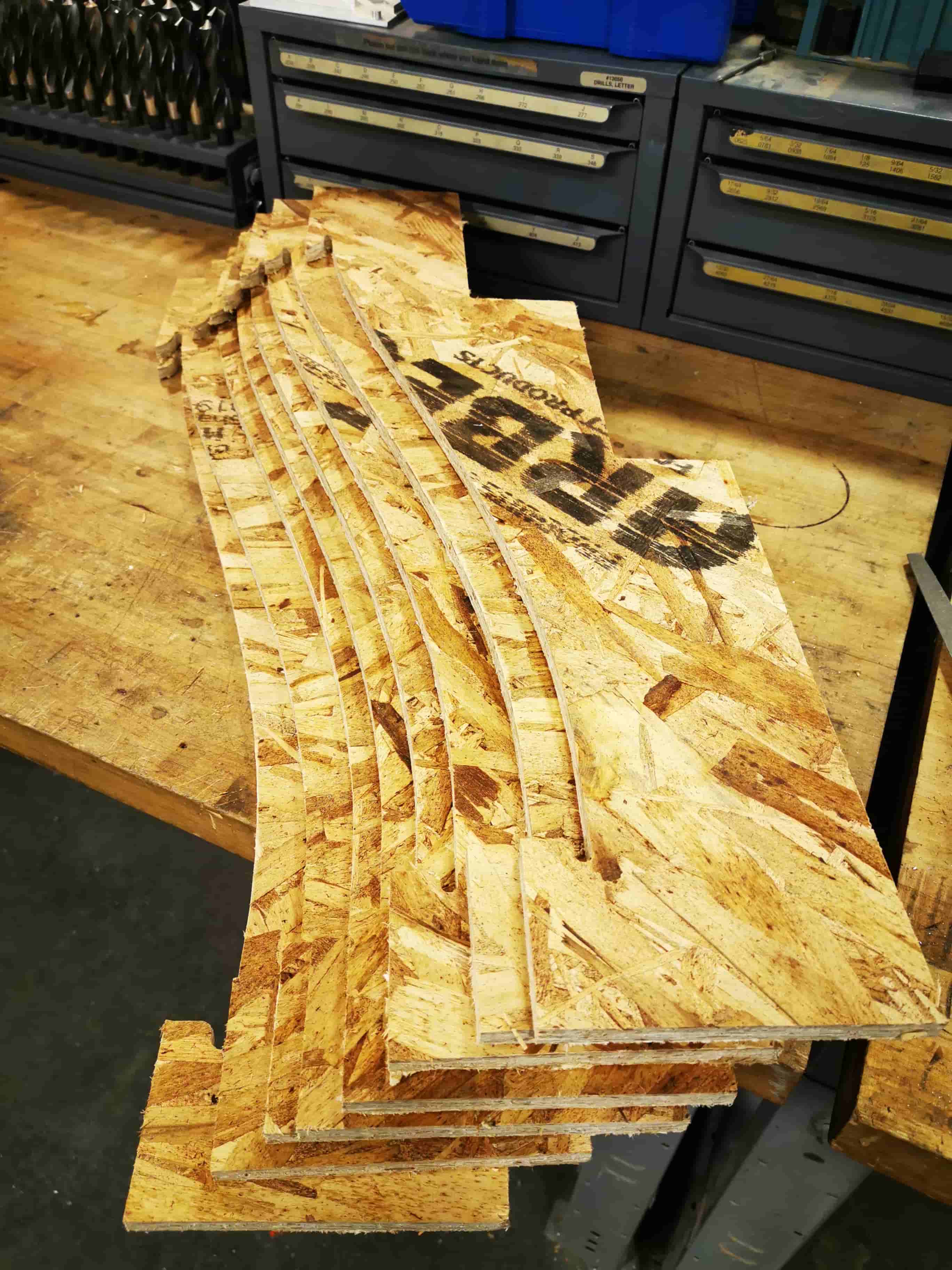
Once finished the OSB milling, I started with the playwood. It was needed to design living hinges and decide the separation of the horizontal lines and teh depth of the milling line

Milling the playwood was pretty good and so time consuming

Once milled the plywood with the desired geometry, I assembled the geometry to get ready to be glued.
After waiting for two days each one, the piece were unmolded and placed
The molded wood was glooed and atached all together in the lamination room
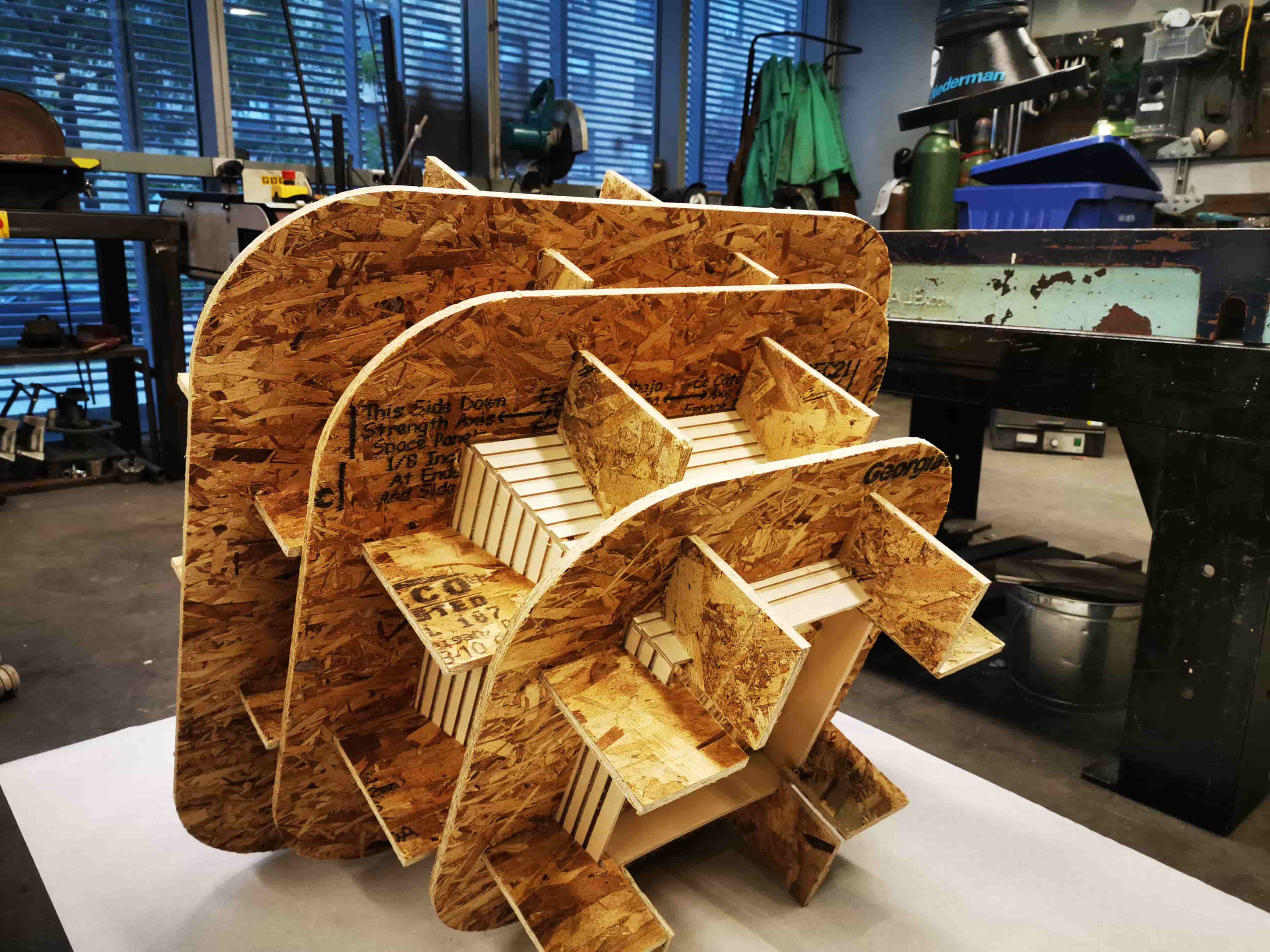
As soon as the wood glue was dry, I started with the other duct
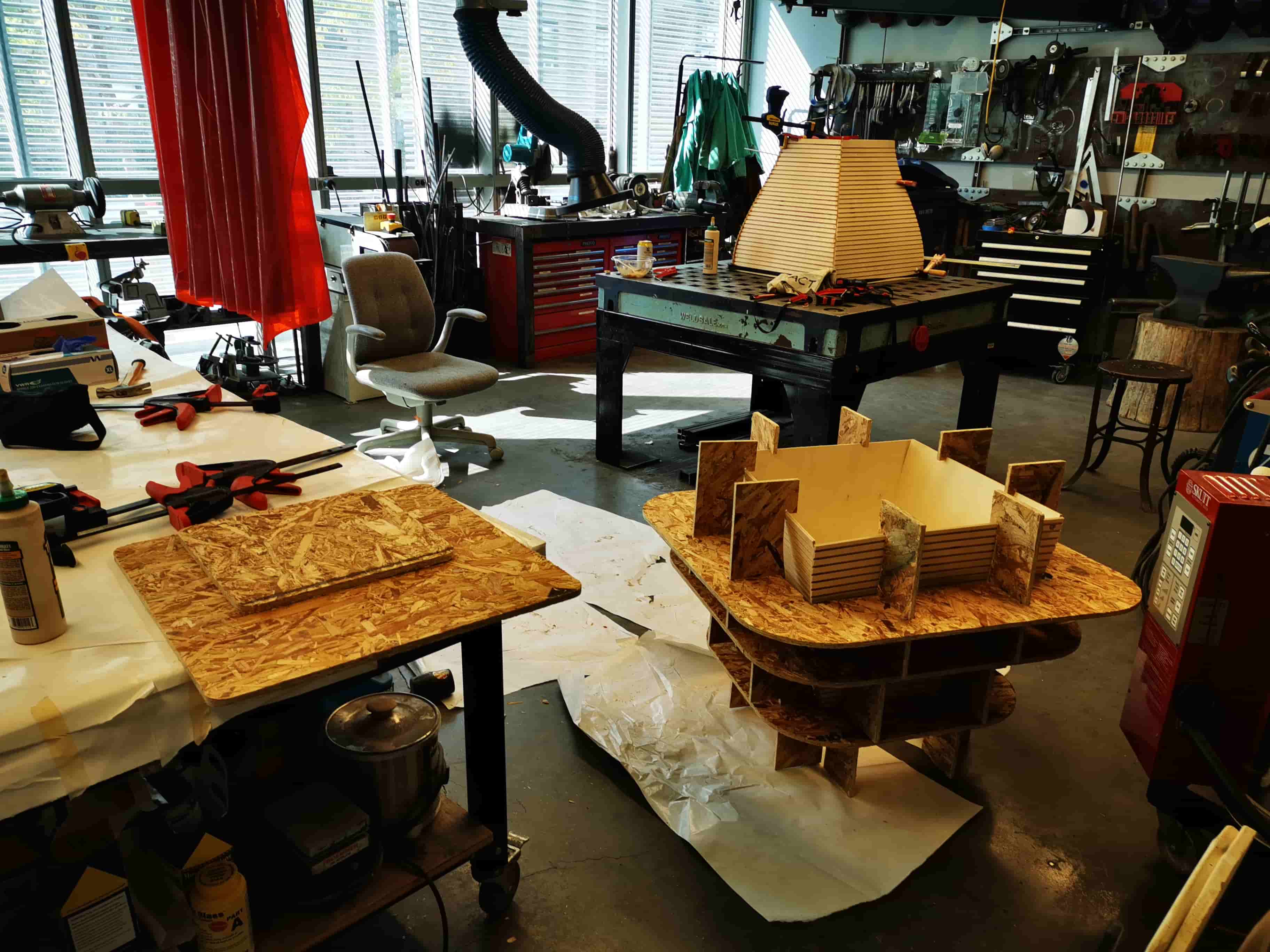
Finished and unmoulded both of the ducts, I applied a decent amount of time sanding all edges and making the piece look good. Right now, the piece is only holded by the glue. I need to fix externally this guy with Aluminum Vshape profiles I ordered last week.
To make them be able to adapt to the shape, Im going to cut both sides to make a living hinge style alu profile!
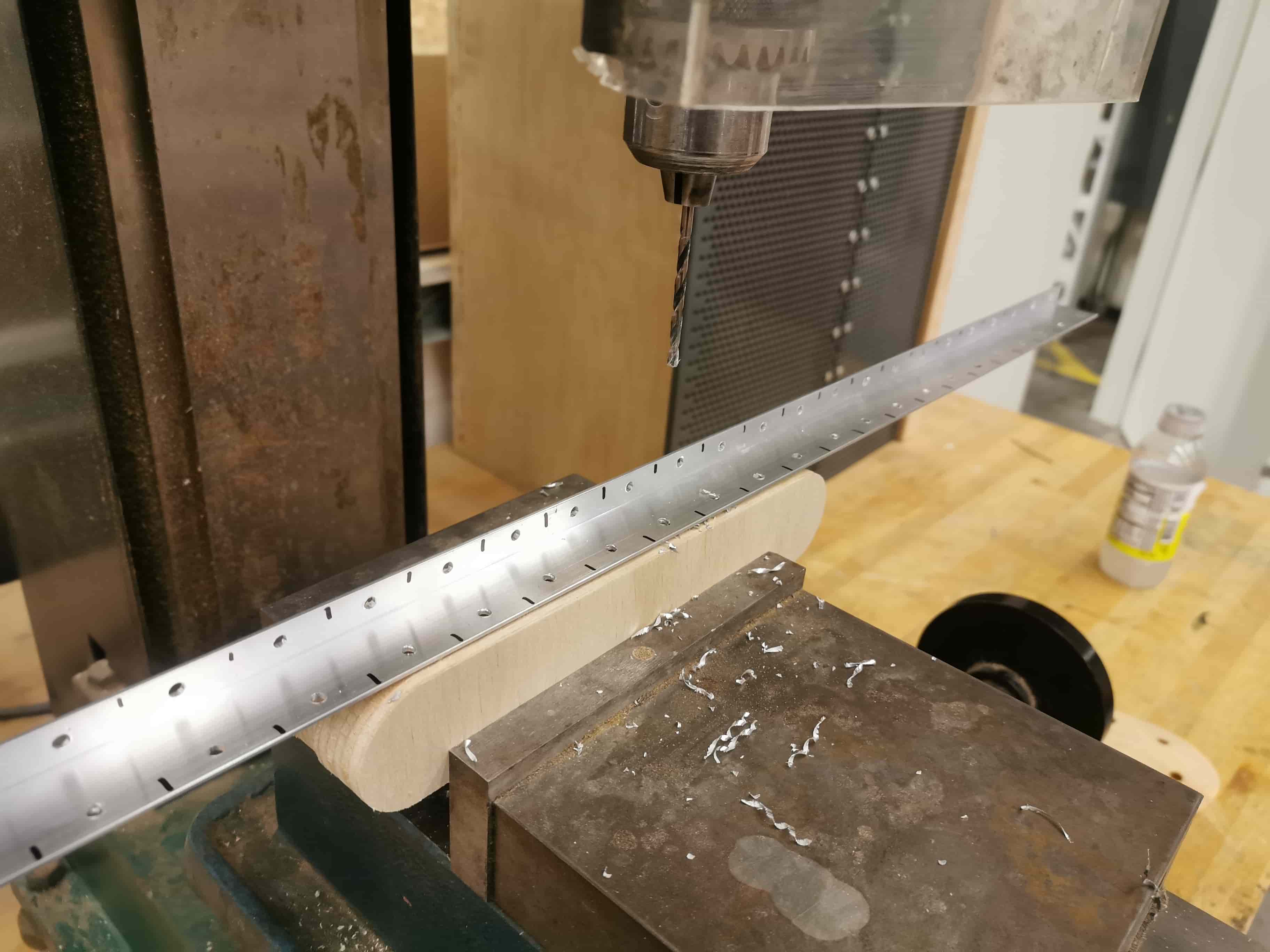
I used the vertical yaw and the vertical drill to shape my aluminum profile.
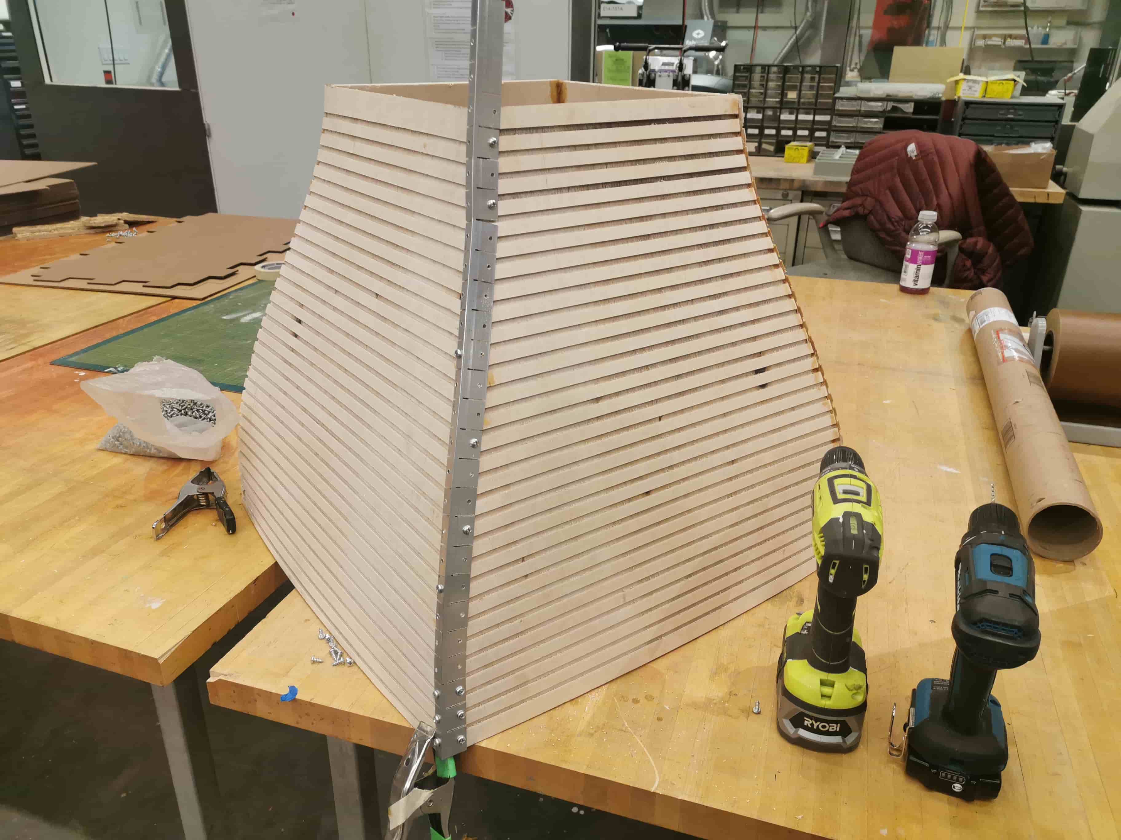
Once I did this for the 8 edges of my curvy shapes, I started working in the main duct. The assembly of the box was so sweet, zero problemo
I used the vertical yaw and the vertical drill to shape my aluminum profile.
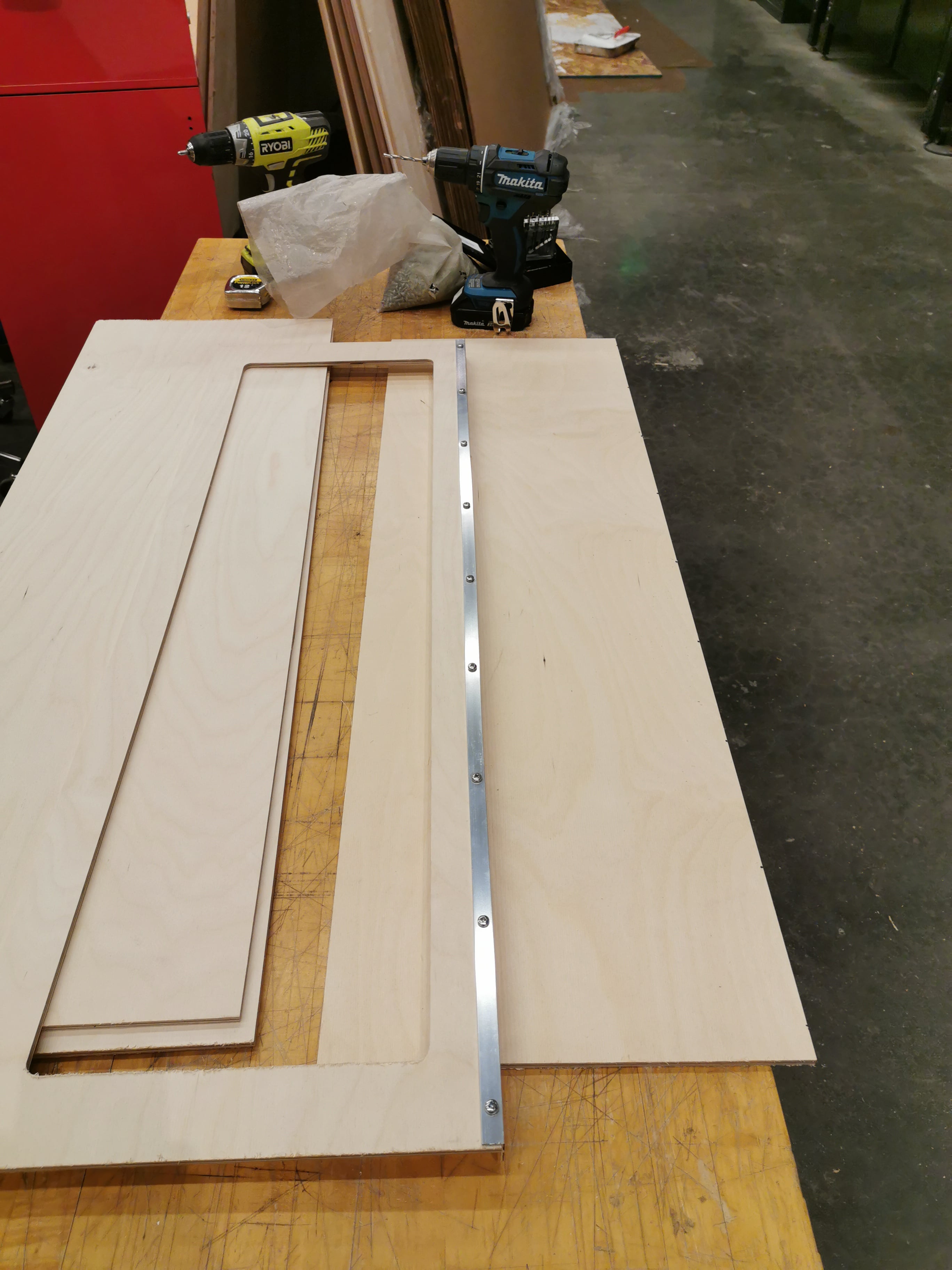
Start taking shape!
I used the vertical yaw and the vertical drill to shape my aluminum profile.
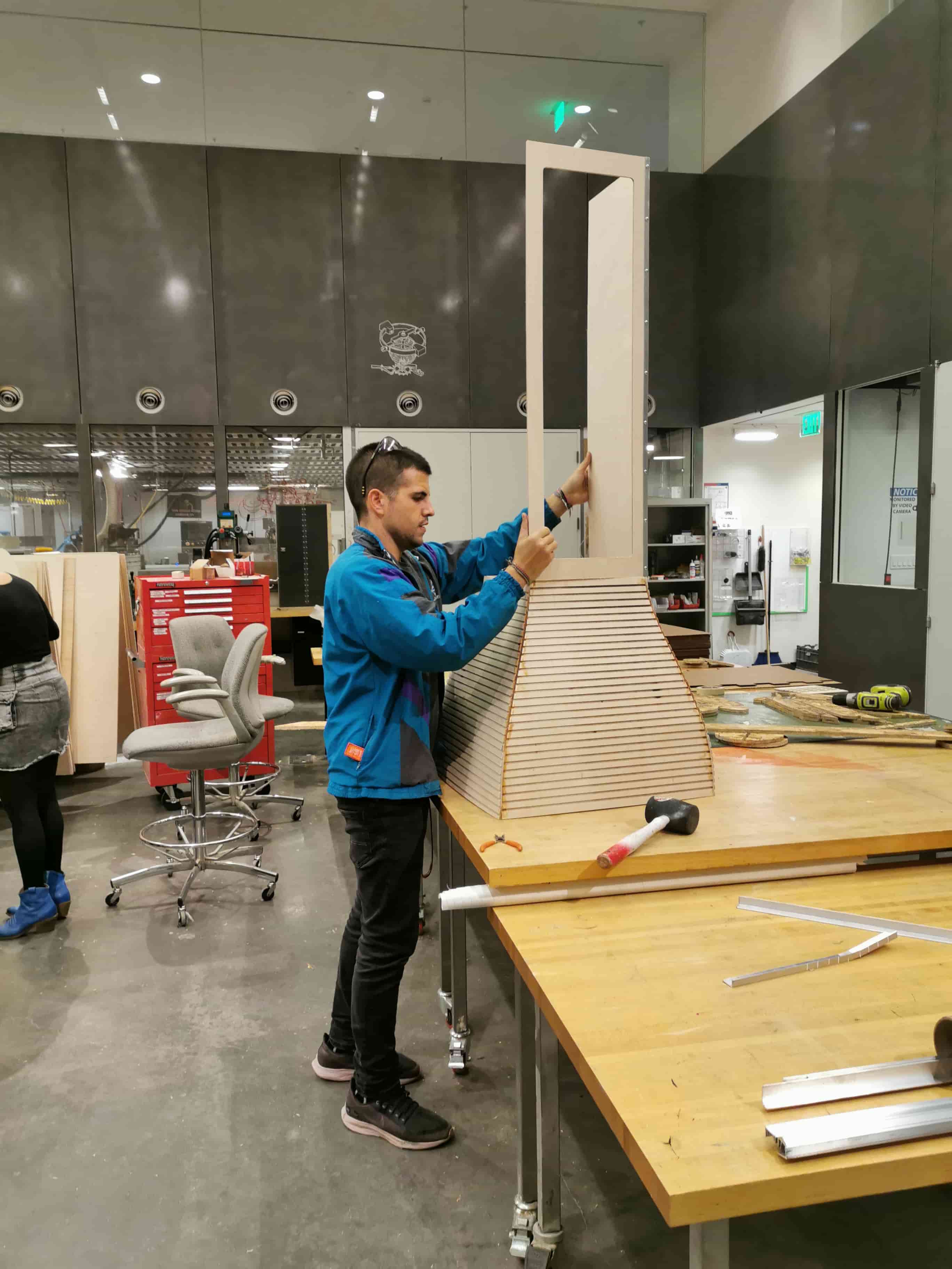
I used the vertical yaw and the vertical drill to shape my aluminum profile.
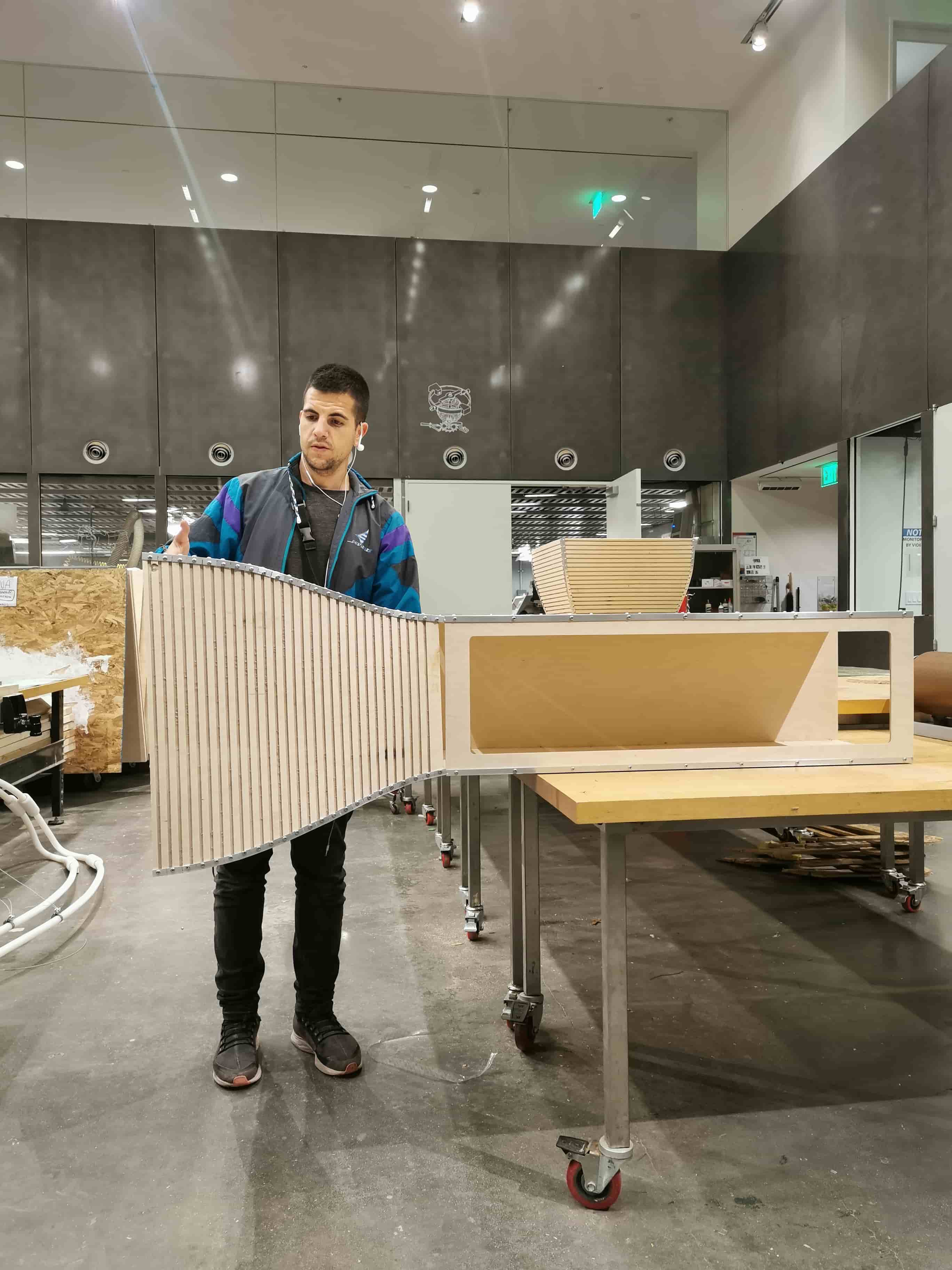
Once each separated element was assembled, I was ready to mount all with the rest of the pieces I ordered in McMaster
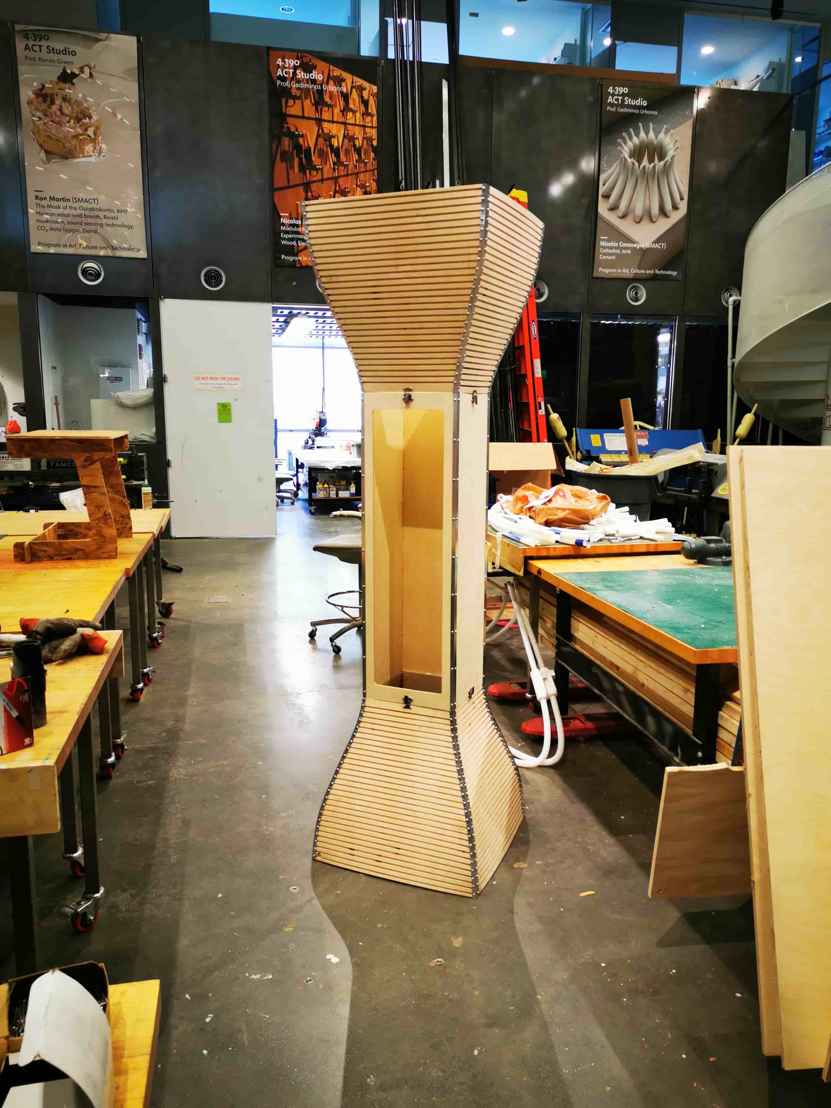
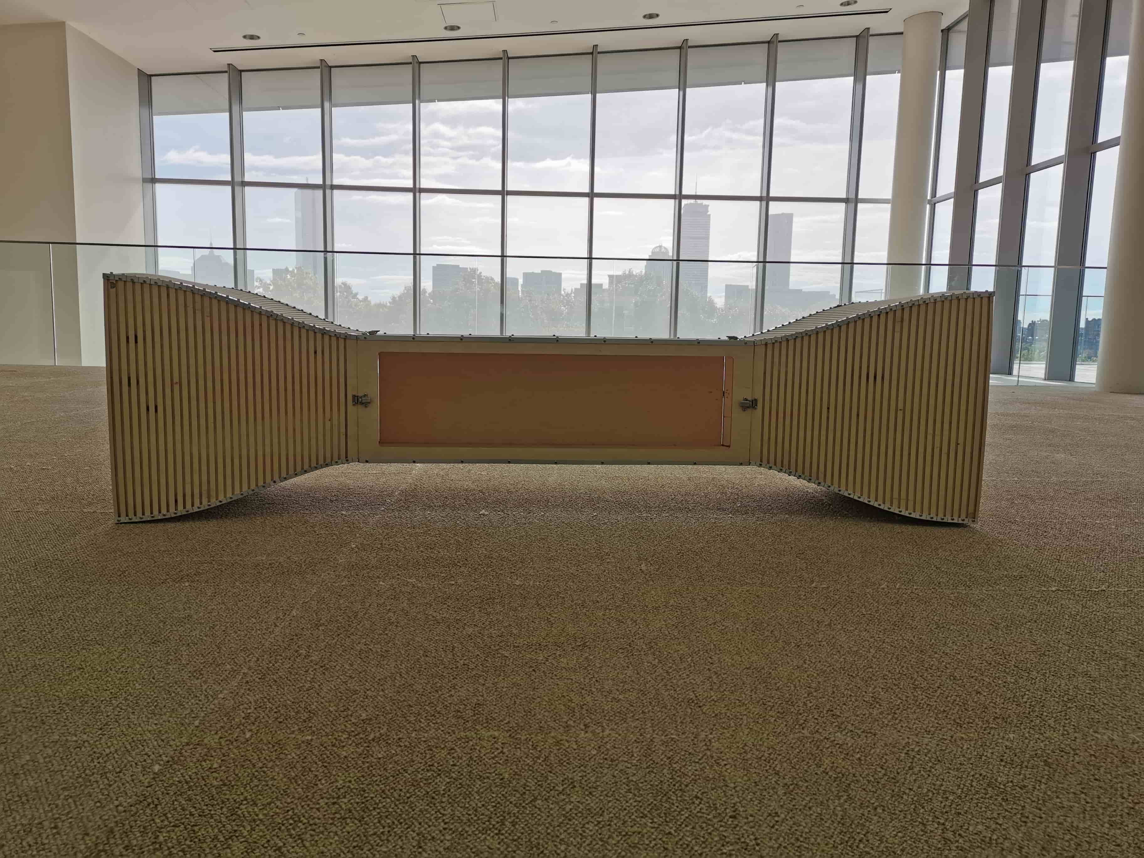
Assembled! The main structure of the wind tunnel is ready to start playing with it!
I want to advance things I have to do for my wind tunnel, and most of them will be cutting metal in different techniques. The things I am going to manufacture for myself this week are:
Using the Waterjet OMAX 55100
When forming the curved shapes in wood of the intake and outlet in the Make Something Big week, the tension of the wood due to it was formed in dry, made the big area of the intakes be slightly curved. This forced me to manufacture some interior beams to be as square as possible. Potentially, I will use those beams to supports bases to assemble over them the duct nozzle and also the laminarizing honeycomb
To make that, I designed in Fusion those beams with a japanese style joints in the corners that could be able to maintain allways an orthonormal position between them
Waterjet is a process in with the shape that the water with the abrasive agent takes is kind of a cone. This factor can be neglectible for thin plates but, for pieces that thickness is not neglectible (mine was 20mm aluminum) this effect can have a notory taper angle. This can be solved directly from SW without any problem. There is no calculation that estimate the angle correction for an specific thickness, so that is why I made some test in the Omax before cutting the whole 4 pieces.
After testing, the assemblyl was pretty straight forward. The tolerances of the water jet parts are awesome, lettin this part to have a really nice joints. To secure rhe beas that will support the fans, I drilled and screwed the joints to provide stability.
After assembel the square frame, I assembled it into the entrance of the duct and the result were so satisfying


Another element I waterjet was the flat plate thata will holds the computer fans. I followed the same process. Design in Fusion, extract a dxf and waterjet it.
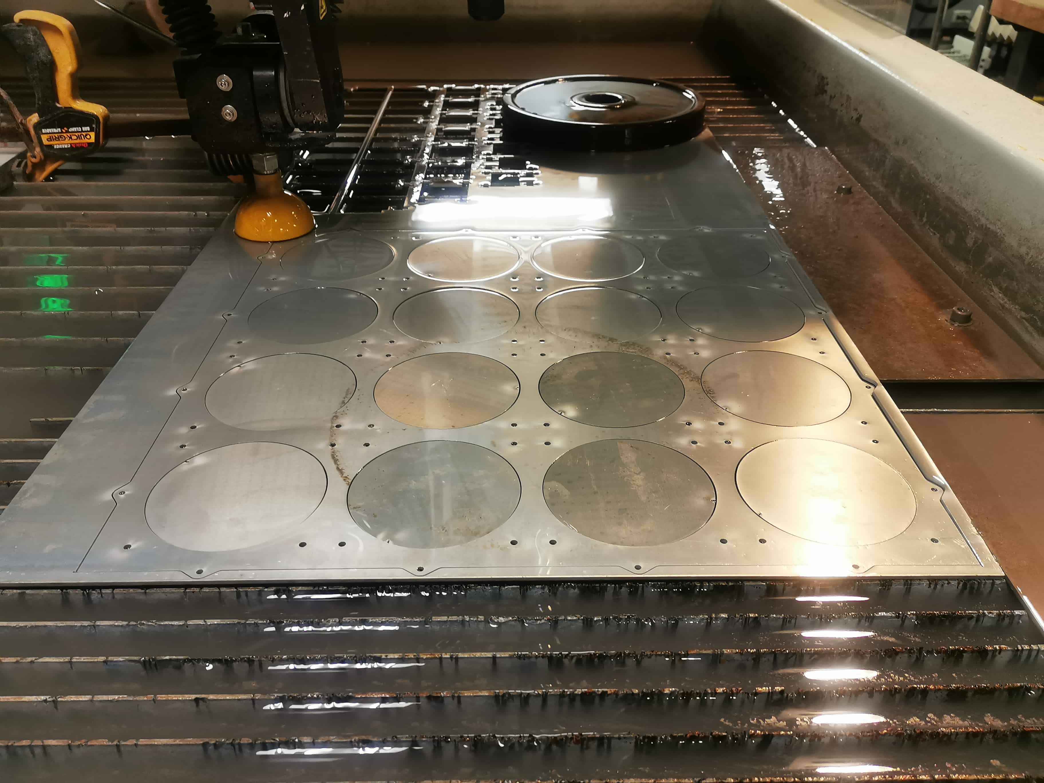
This element was manufactured in an aluminum sheet of 3mm thickness.
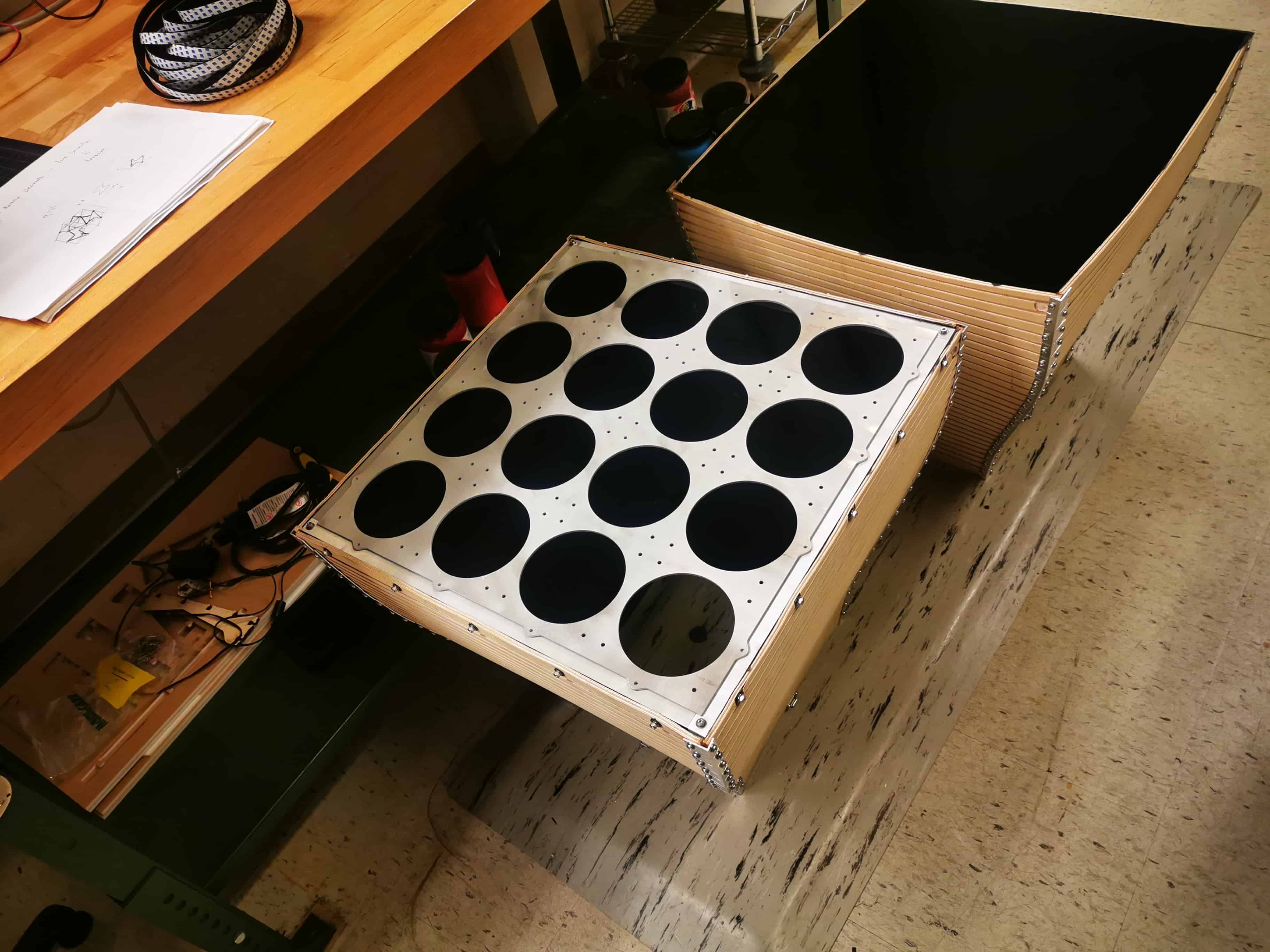
Using the Zund! < 3
The Zund is a machine that since the first day I meet her, I fall in love with. Ive never experienced a faster gantry machine with that precision, repetibility and modularity.
As the zund is a 2.5 axis machine, all you have to import is a DXF file splitting by layers the herarchy of the orders you want to make.
When you have a machine and tools able to go up to 50k, routing is kind of scary even though you have deep previously experience with CNC machines. 50k allows the machine to mill so so so fast. But the worst part is once you get use to it and go back to the Shop Bot, you want to die because it goes way more slower than the Zund
Acrilic and HDPE milling were done without any problem and the window and the HDPE supports were assembled beautifully


Never forget countersinking

The stability of the wind tunnel in a table was critical. My first thought was to hang it from the wall but there was so many possible movements it could have.. So I decided to make some conventional supports. I designed them in Fusion and used the Zund to mill them.
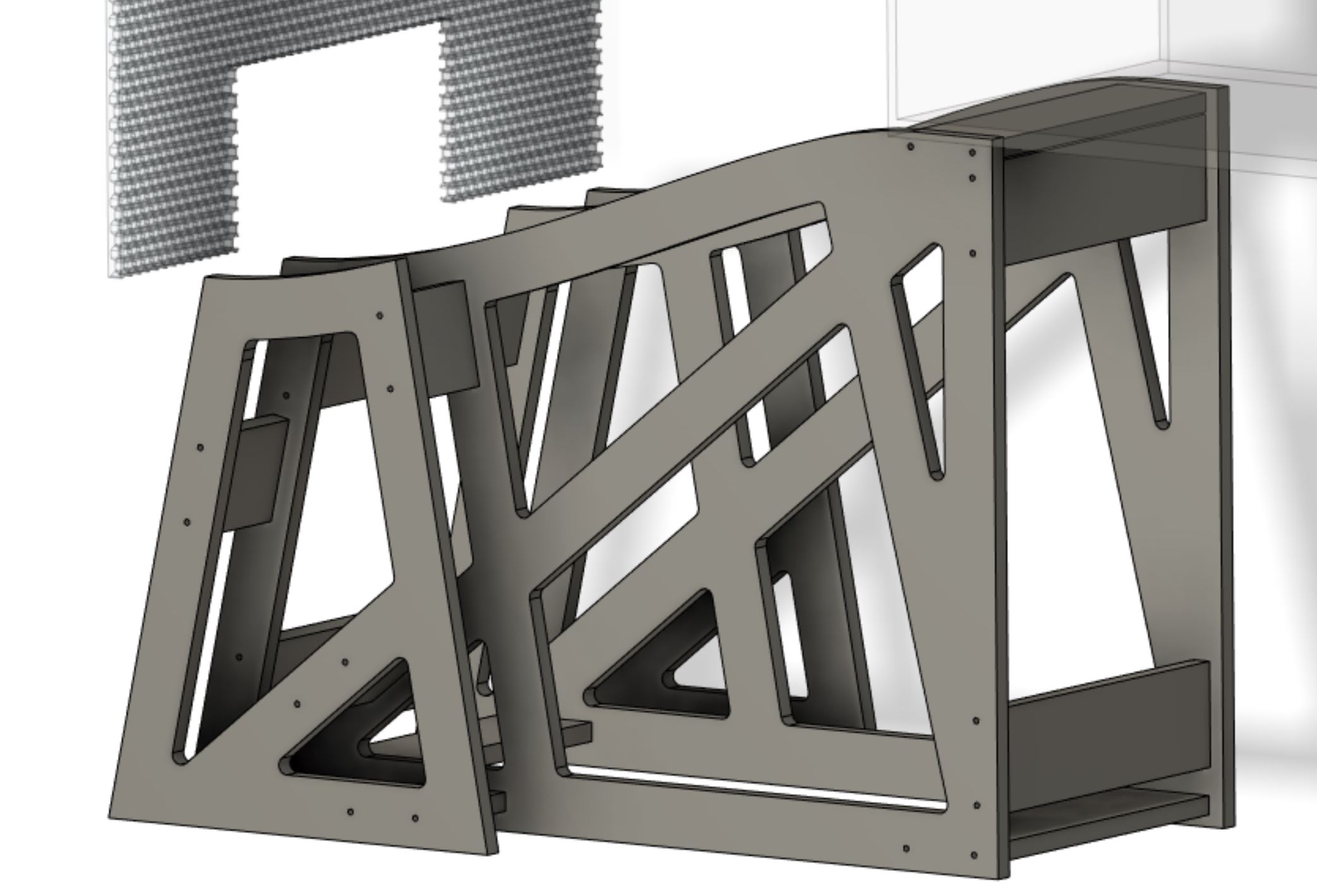
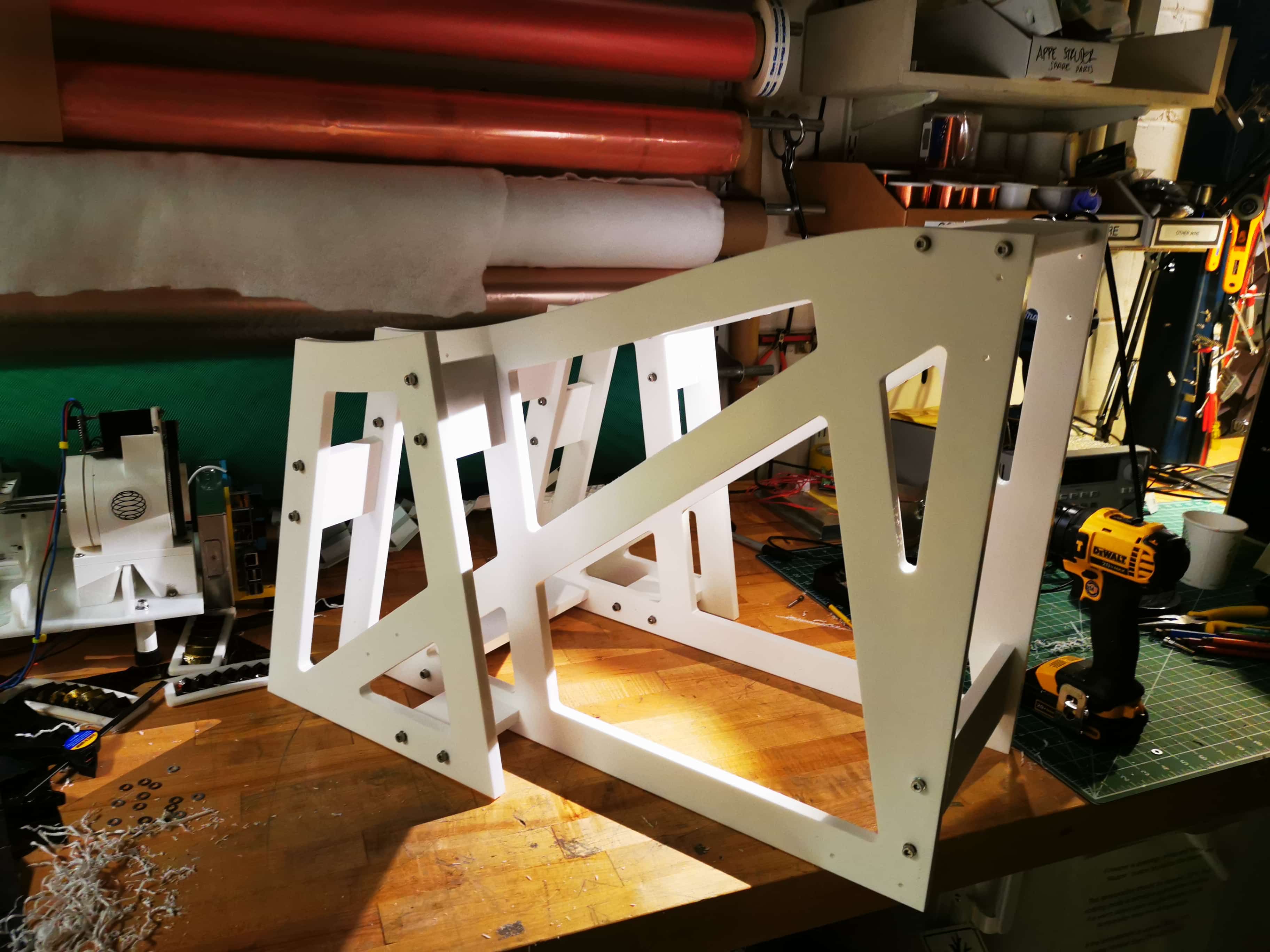
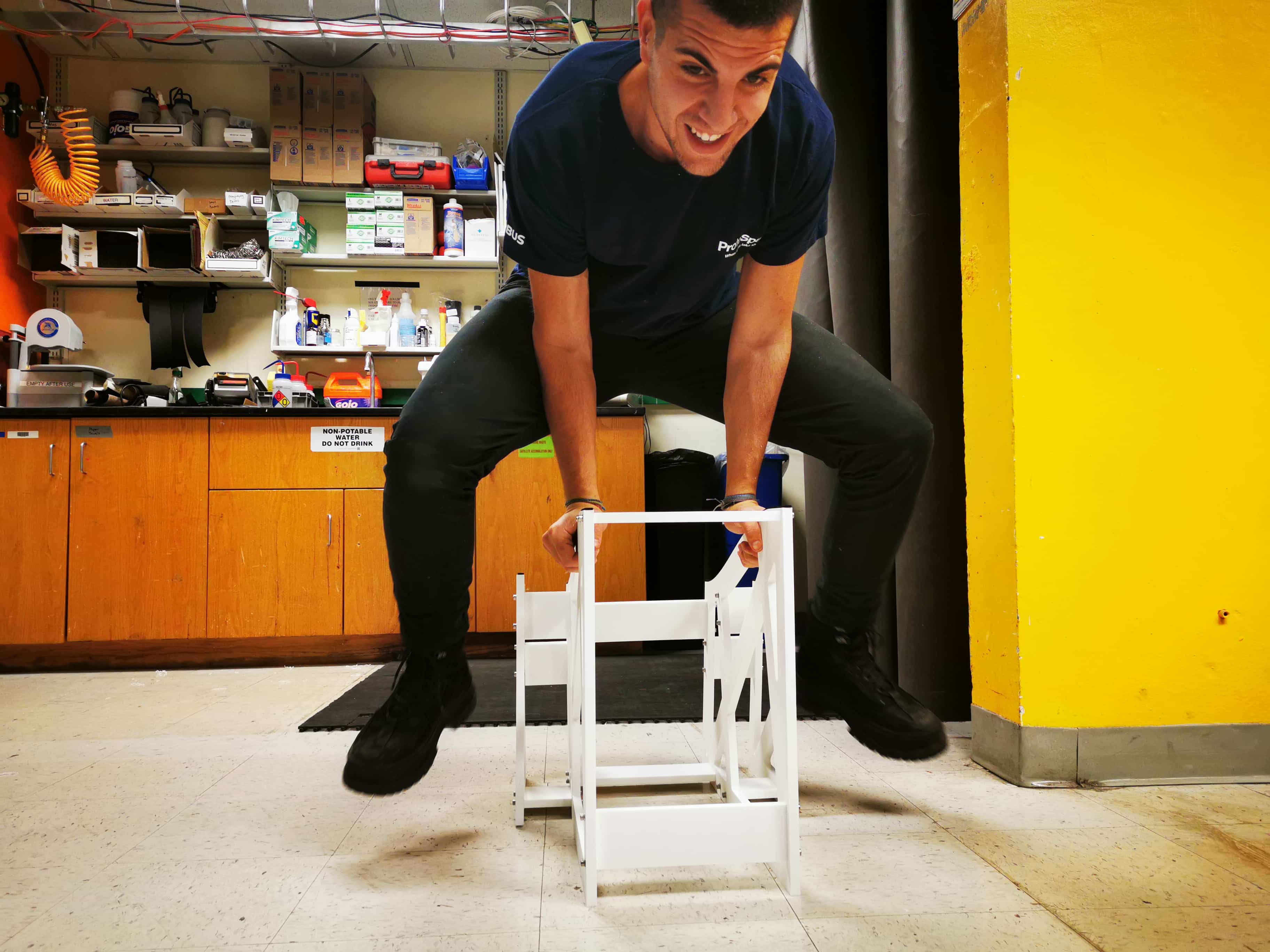
I applied an FEA and a shape optimization to ensure I will never break those guys. And I kind of test them. So so stiff
EDM!
For the sensing arm of the wind tunnel that will read the forces of the load cell, I want to EDM a monolithic flexure structure in two directions that will translate any force applied as a momentum to this canteliever beam into orthonormal forces. I am higly interested on that due to I want to read lift and drag separately.
For this prupose, I designed the load cell in fusion. The thickness of this element will be 0.75 inches that will be subtracted from a 1 inch by 1 inch aluminum bar.
We need to EDM the interior of the load cell shape, cut the wire, re wire the machine and cut the perimeter. This is due to I really want to control the distance between the interior of the load cell and the exterior walls. The stonebridge of strain gauges will be so sensitive to the deflection and we want to use the EDM tolerances to make this load cell as precise as possible
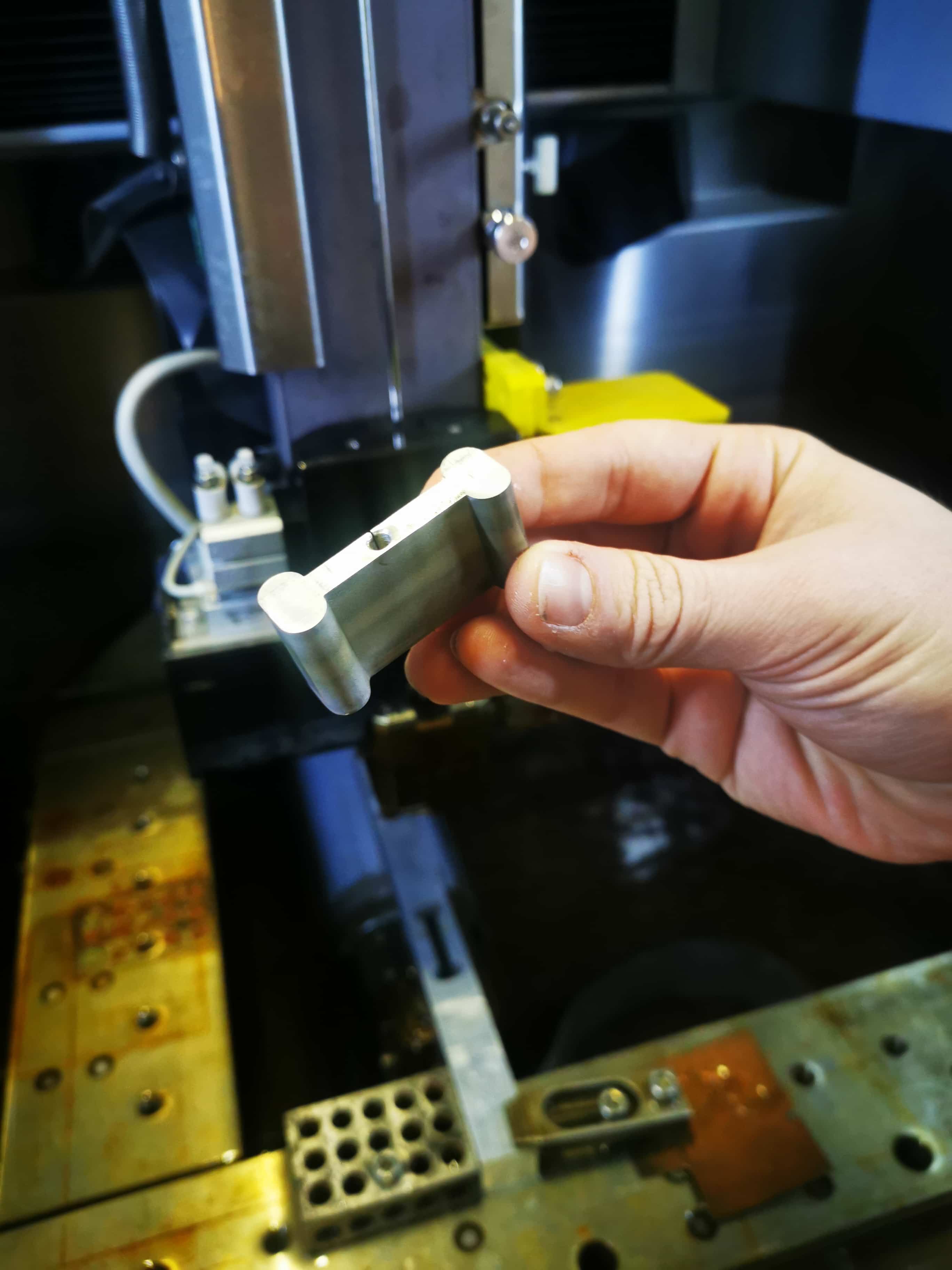
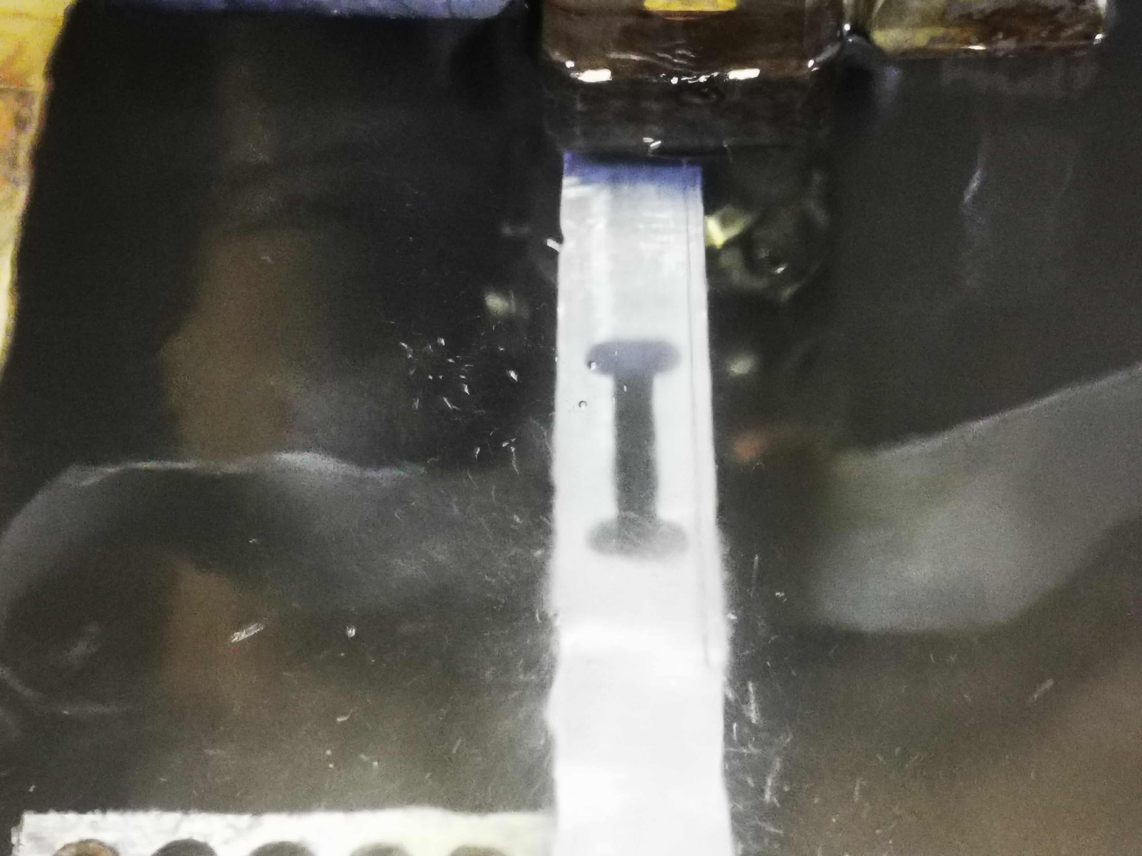
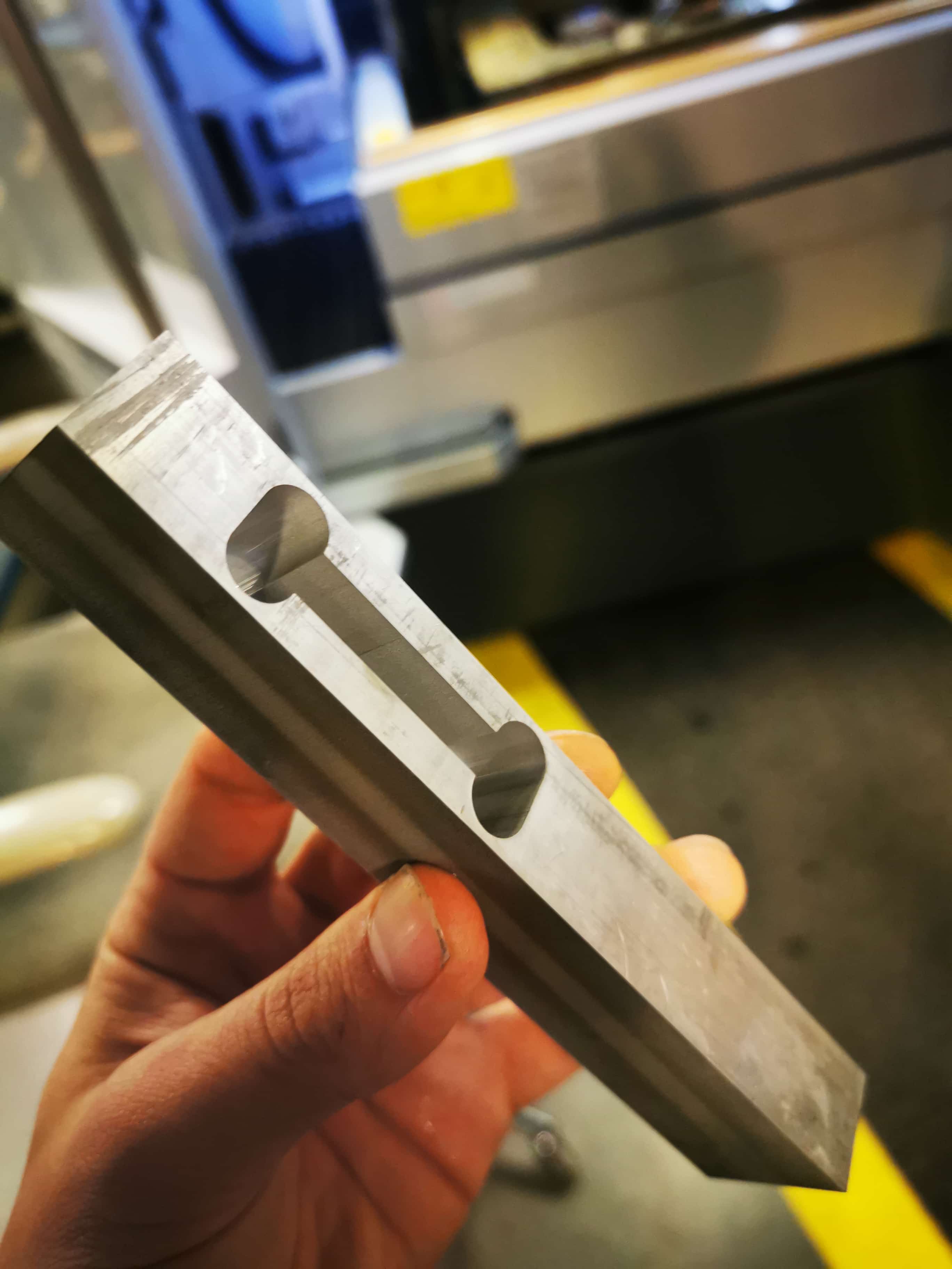
By far, EDM is the most satisfying process I ever tested.
Also I spend so many time making the cables longer and routing stuff. Here you can find a sample

Electronics time!
To control the active elements of the wind tunnel, I have to design some PCBs and make them work. This course I have learn how to use Kicad and I am starting to feel more confident with it.
The two main elements I have to control are computer fan speeds and reading load cells
Computer Fan Control System. Generating PWM in a ATTiny44
Computer fans I am using are a brushless edition of 4 wires. Red and black are main power supply that goes into 12V, yellow cable is the PWM control line directly from the ATTiny (0-5V) and the blue one is just a feedback to measure the velocity. I am not interested on using thi one due to I want to read the velocity in the duct, not in the intake and for that, I will use a tiny pitot pipe.
I am going to design 3 different PCBs. One, will be the power distribution. I am going to get 12 volt from the power supply, I will reduce them into 5V and I will distribute this to the other ATTiny to be able to operate. The rest of the 2 boards I will make are just for safety reasons.
From 1 output pin of the ATtiny I will generate a PWM signal based on the reading of the input pin in wich I will connect a potentiometer. I will use the internal register of ADC to translate this signal into a digital value from 0 to 255. And I will apply a PWM signal based on that reading. Control lines use to consume really low current, but just as a double safety, I will connect an N-Mosfet on that pint to boost intensity up to 1.7 amps. I will connect there only 8 fans so I will make another PCM to control the rest of the fans.
The schematics looks like the following:
One confession of this project is that, I founded only 14 computer fans, not 16 :(. So I had to order 2 new fans. The same PN were completely obsolete on the internet so I had to order 2 fans with the same dimentions. My mistake was that I ordered 4 wire cable fans, not 2 cable fans...... This led me to have to control them with voltage signal rather than PWM. So I had to make another board that control this voltage with an H Bridge. I implemented in that board the Power management. The board looks like the following.
Also, I tried to control directly the load cell signals using an ADS123 chip. To do that, I used an ATmega32u4. The board to control it and read it looks like the following
Once manufactured all PCBs they looks like this


And here the pcb that controlls the load cells. Finally I had probelms to control 2 at the same time so I used some arduino platform for the exam.

I wrote some code to control the PWM signal but I had a problem. I needed to increase the frequency of the signal up to 33MHZ in order to be readable by the fan. Thanks to Zach again he helped me to modify the registers of my code to do that.
#include #include #include #define IN1 (1 << PA3) // IN1 #define IN2 (1 << PA2) // IN2 #define oa (1< < PB2 ) int analogData; #define pot_pin (1 << PA7) // defining Mosfet1_port which is an output that controls mosfet1 void setup() { static uint16_t count; static uint8_t cycle; CLKPR = (0 << CLKPS3) | (0 << CLKPS2) | (0 << CLKPS1) | (0 << CLKPS0); ADMUX = (0 << REFS1) | (0 << REFS0) // Vcc ref | (0 << MUX5)| (0 << MUX4)| (0 << MUX3) | (1 << MUX2) | (1 << MUX1) | (1 << MUX0); // pa7 ADCSRA = (1 << ADEN) // enable ADC | (0 << ADPS2) | (1 << ADPS1) | (1 << ADPS0); // prescaler /128 ADCSRB = (0 << BIN)| (1 << ADLAR); // direct mode // left adjust; clear(bridge_port, IN1); output(bridge_direction, IN1); clear(bridge_port, IN2); output(bridge_direction, IN2); DDRB = ( 1<< PORTB2); TCCR0A = (1 << COM0A1) | (1 << WGM00) | (1 << WGM01); TIMSK0 = (1 << TOIE0); TCCR0B = (1 << CS00); TCCR0A |= ((1<< COM0A1) | (1<< WGM01) | (1<< WGM00 )); TIMSK0 |= (1<< OCIE0A); } void loop() { ADCSRA |= (1 << ADSC); //with next line… analogData = ADCH; OCR0A=ADCH; } Here there is a go through of how all the system works except for the load cells. SORRY FOR THE VERTICAL VIDEO. I KNOW I SHOULD BE IN THE YOUTUBE JAIL. Also sorry for the spanish
I am presenting a low speed wind tunnel! The function of this element is to be able to double check aerodinamical analysis in a real scenario by providing nozzles and ducts that will have a constant speed and sensors to see how the aerodinamical forces behave.
Wind tunnels are well known around the world and history, specially in aerospace industry. MIT had one of the most famous in the world that now its being replaced.
I have design the physics inside, the outside cad, the system integration, the load cells system, the physical supports and many more rabbit holes that I cant remember right now
Material used are: Wood, from Massachussets, aluminum (McMaster but I dont know the origin), 16 computer fans founded at CBA, electronics, HTPA from another american company and houndred of screws and nuts
Wood 150 dollards, Honeycomb 100 dollars, Aluminum stack from CBA, load cells were 15 dolars, acrilic 50 dolars, mcmaster orders in miscelaneous 90 dolars. I didnt make yet a formal study but I guess around 400 dolars.
The wood frame structure, the fan supports, the fan logic and control, the power supply system the interior the supports, windows, load cell measurements and sw for that.
Zund Machining, Shop Bot machining, OMAX waterjet, EDM, laser cutter, 3d pprinting, framing curver wood, Roland PCB miller, soldering, painting, glueing and many many many assembly.
First, personally, that I am able to do it! That was a super satisfying one. Second, that It is possible to make a low cost low speed wind tunnel DIY. (I would love to upload to inestructurables due to all the wind tunnels there are kind of meh)
Consistency, I have to study laminarity and speed, but the suction the user can feel is awesome. And its loud, I love it.
I reallly wish I can improve the instrument so CBA can have its own low speed wind tunnel for testing and increase the lab capabilities!
Find here the video :)
back to menu