Week 10. Output devices
So, this week we were asked to learn something more about embedded programming in AVR chips. To be fair, my past week was not such a success in terms of delivery. But it was crutial to be able to have a nice project for this week. Last two weeks I have learn tons of embedded programming, circuits, and signal management. Its been so intense as well as fun.
For the infividual assignment, I decided to make an stroboscopic lamp!
Stroboscopic effect is able to freeze a movement object by flashing an intense light in specific a time when moving. I asked Jiri about the frequencies and some other aspect needed and he gave me nice advices.
Also, as allways, I really want to thanks Zach and Erik. I am learning tons with them. I am starting liking registers and all this stuff needed to code. I wasnt specting that when coding, reading datasheets to know what are you doing with registers wat that crutial.
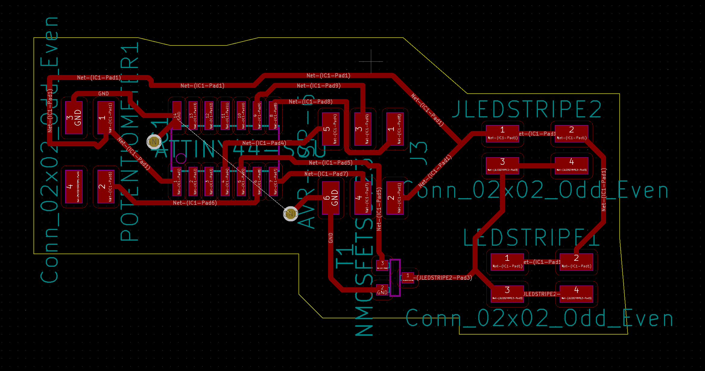
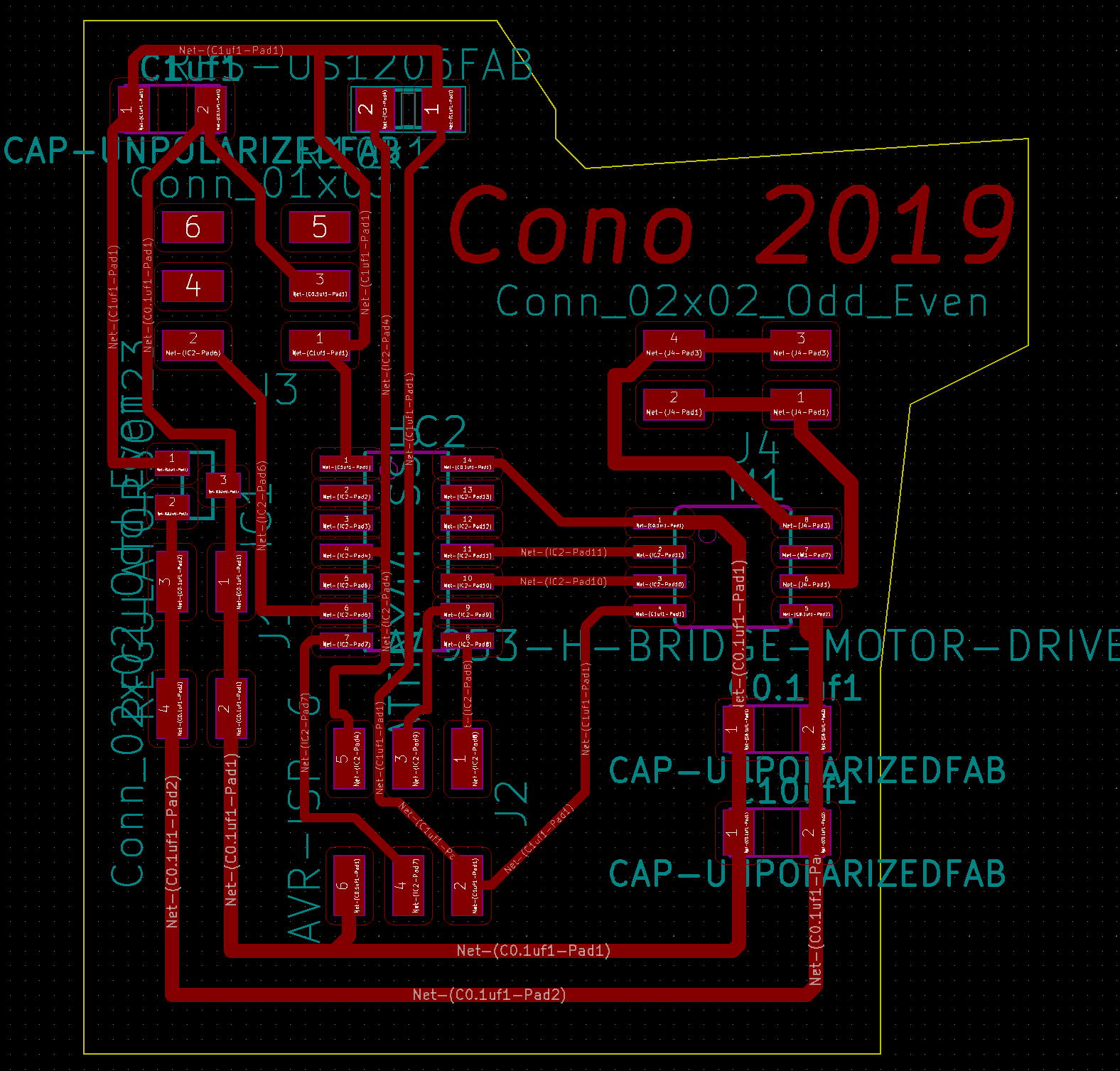
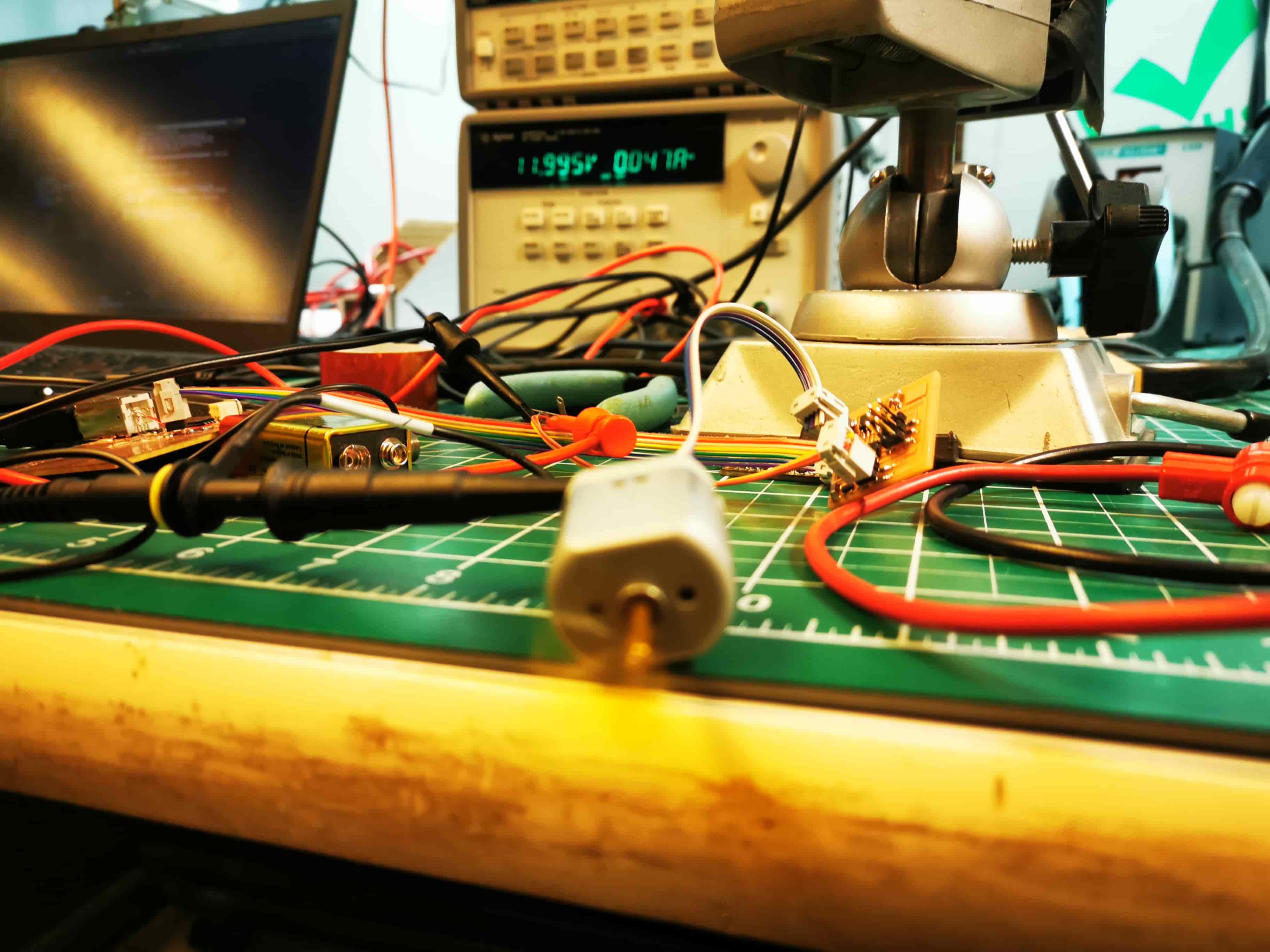
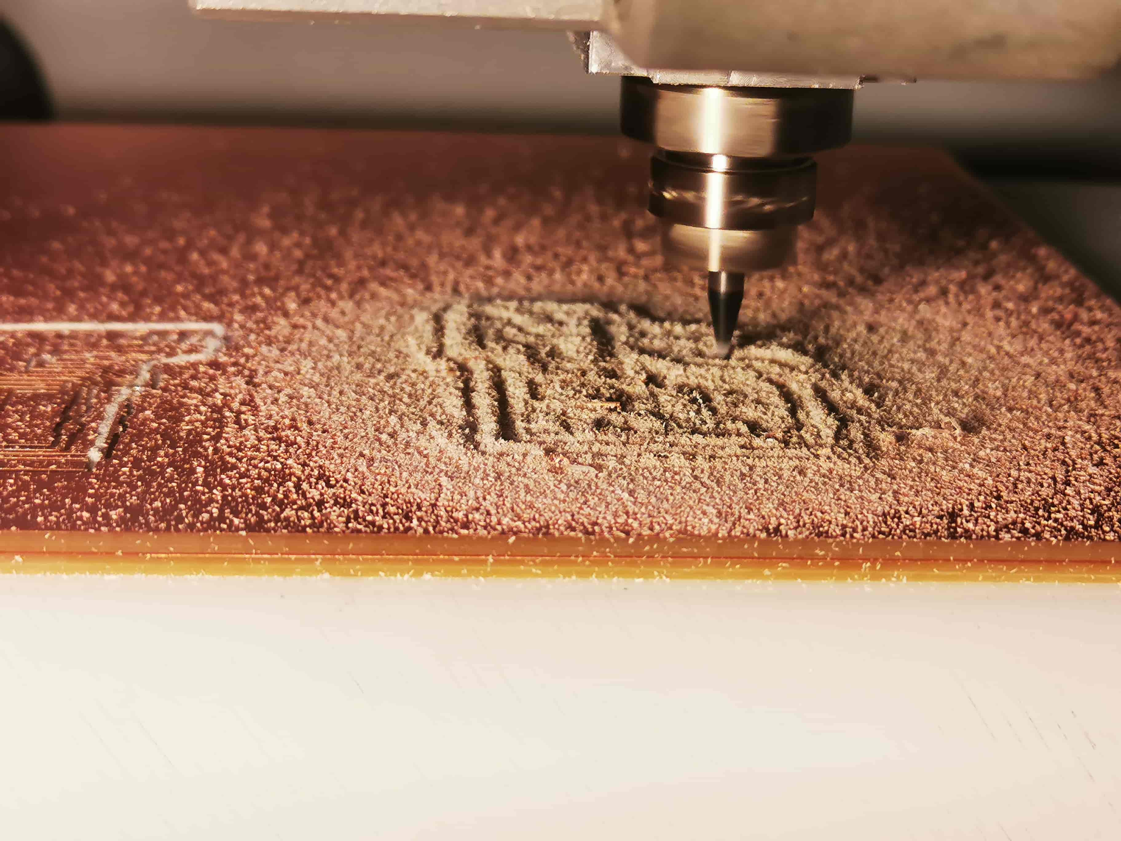
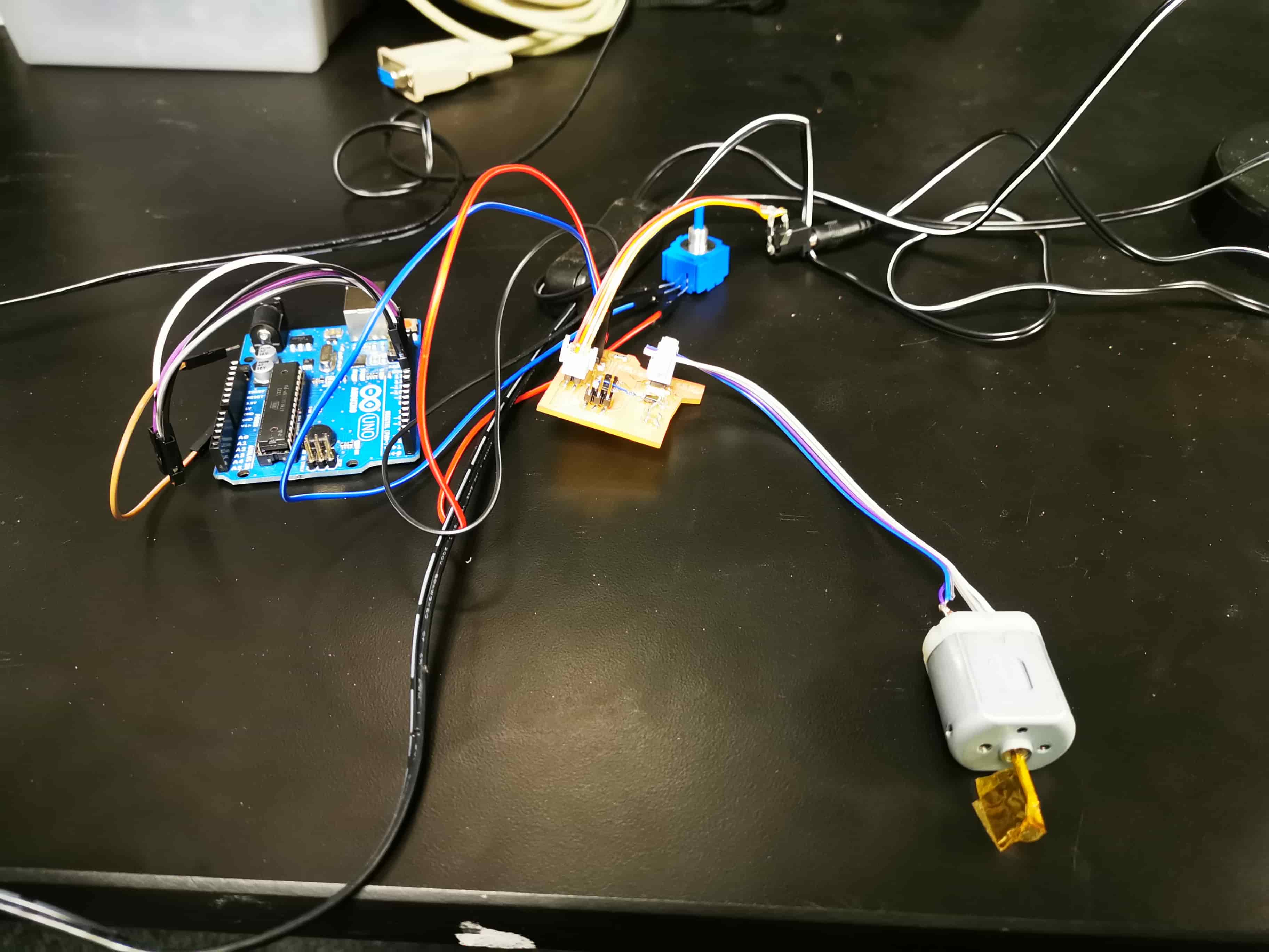
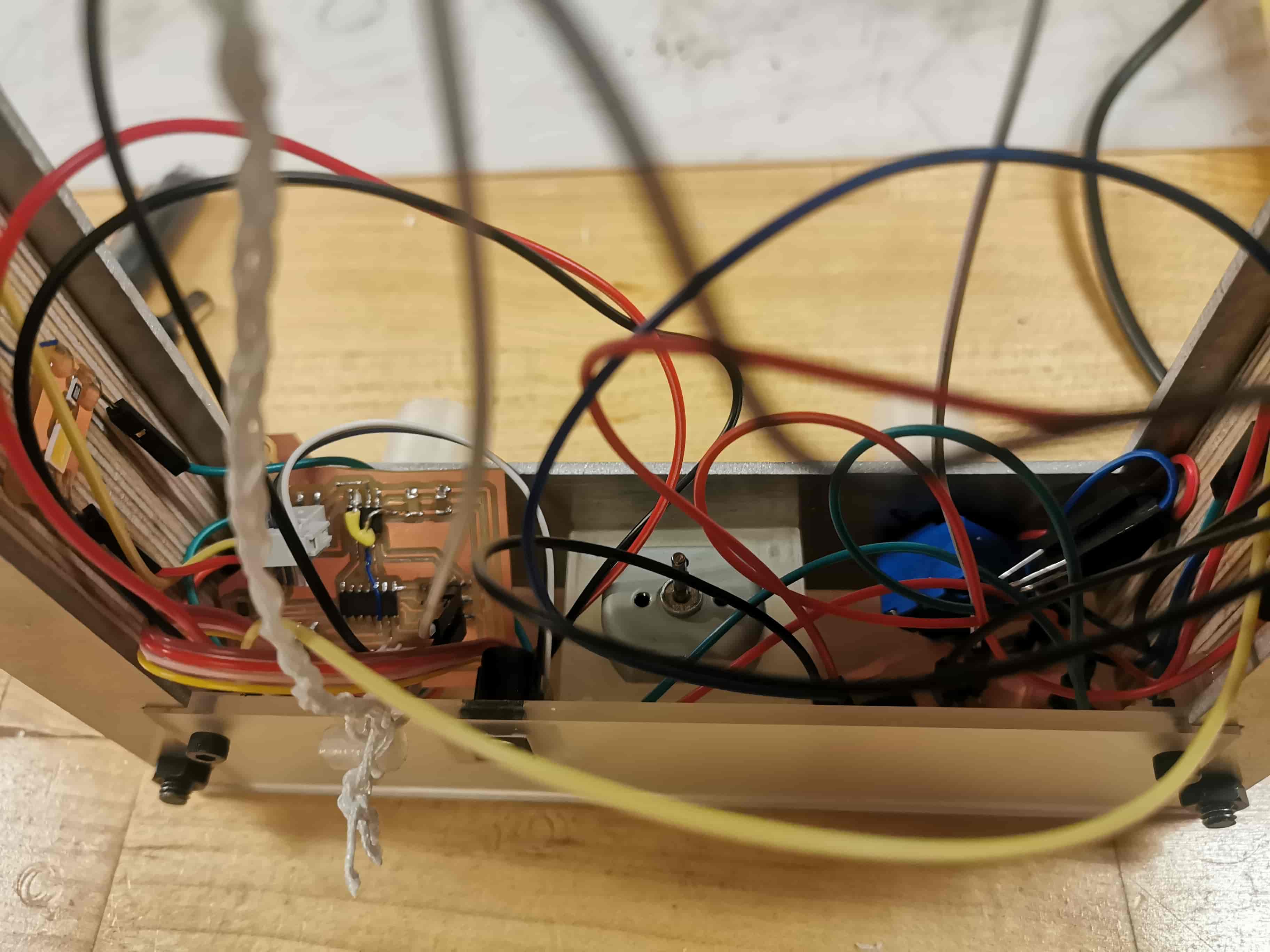
To do the lamp, I needed to control with a input devide (a potentiometer) an output device (home made LED strip). Also, with another potentiometer I will control a DC motor that make an objetc rotate. This is the element (in this case a rope) tht will be flashed. To do that, I designed a circuit with all those components intalled in the correct pin.
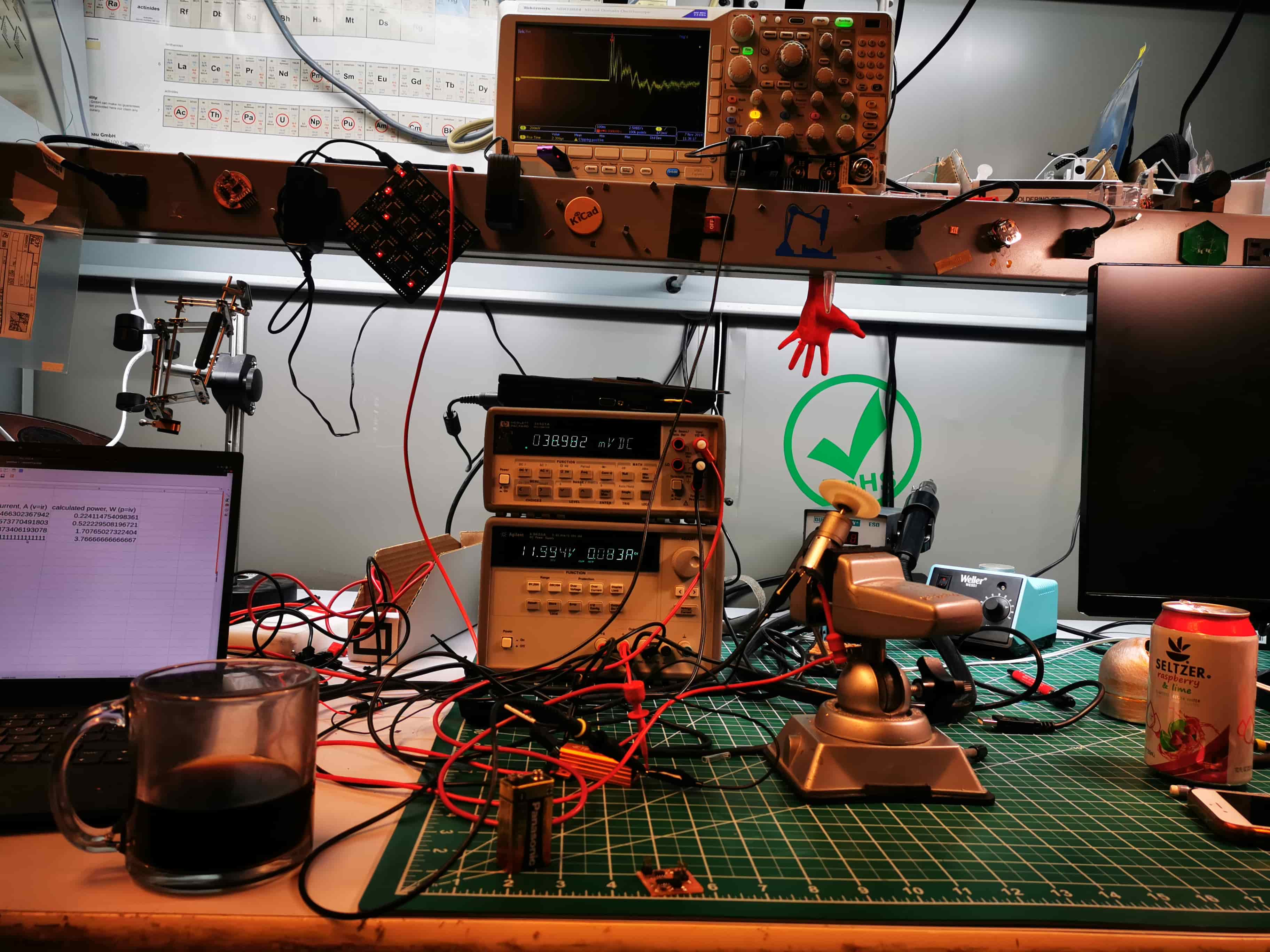
Then, I allowed the ADC in the entrance pin of the potentiometer and I translate the analog signal into a digital signal from 0 to 255. After that, I will generate a PWM signal able to parametrize the duty cycle. I linked both parameters in the code and the result is a nice control of the DC motor needed to rotare what you want to flash and the LEDs! It so fun to see how different components behaves so diferently to PWM signals.
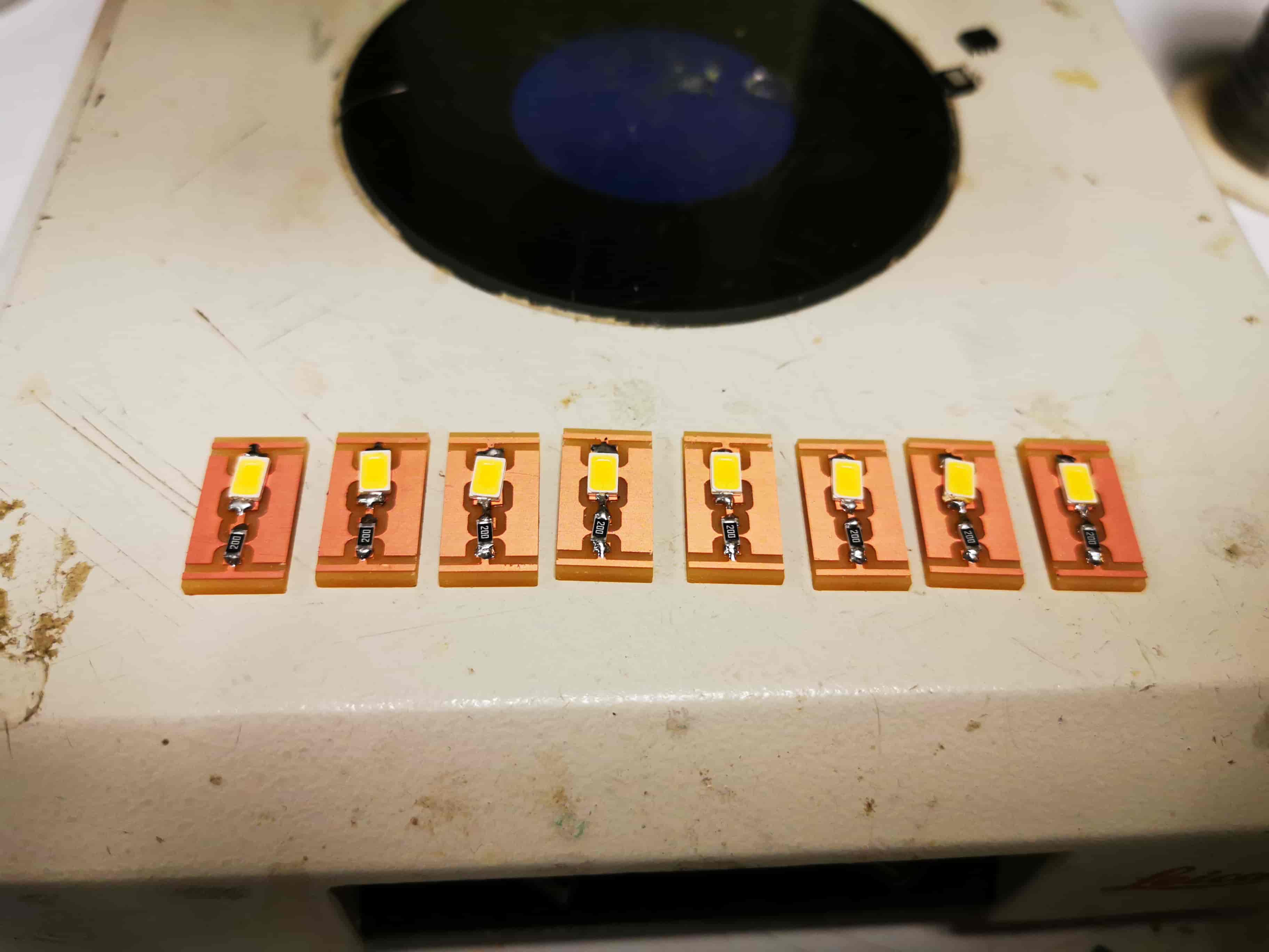
After making all the circuits and PCBs I made a homemade LED strip. Those LEDs are so intense. They consume 5 times more than a conventional LED (100mA) so I needed a N Mosfet to provide the current they ask for.
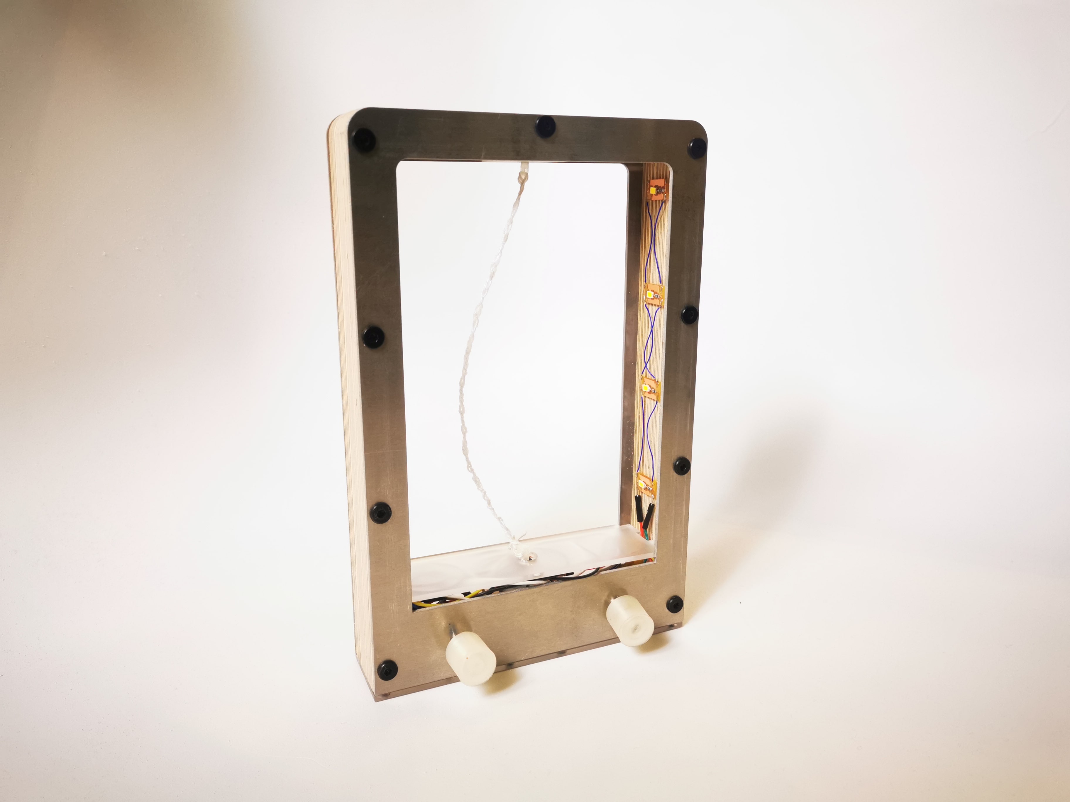
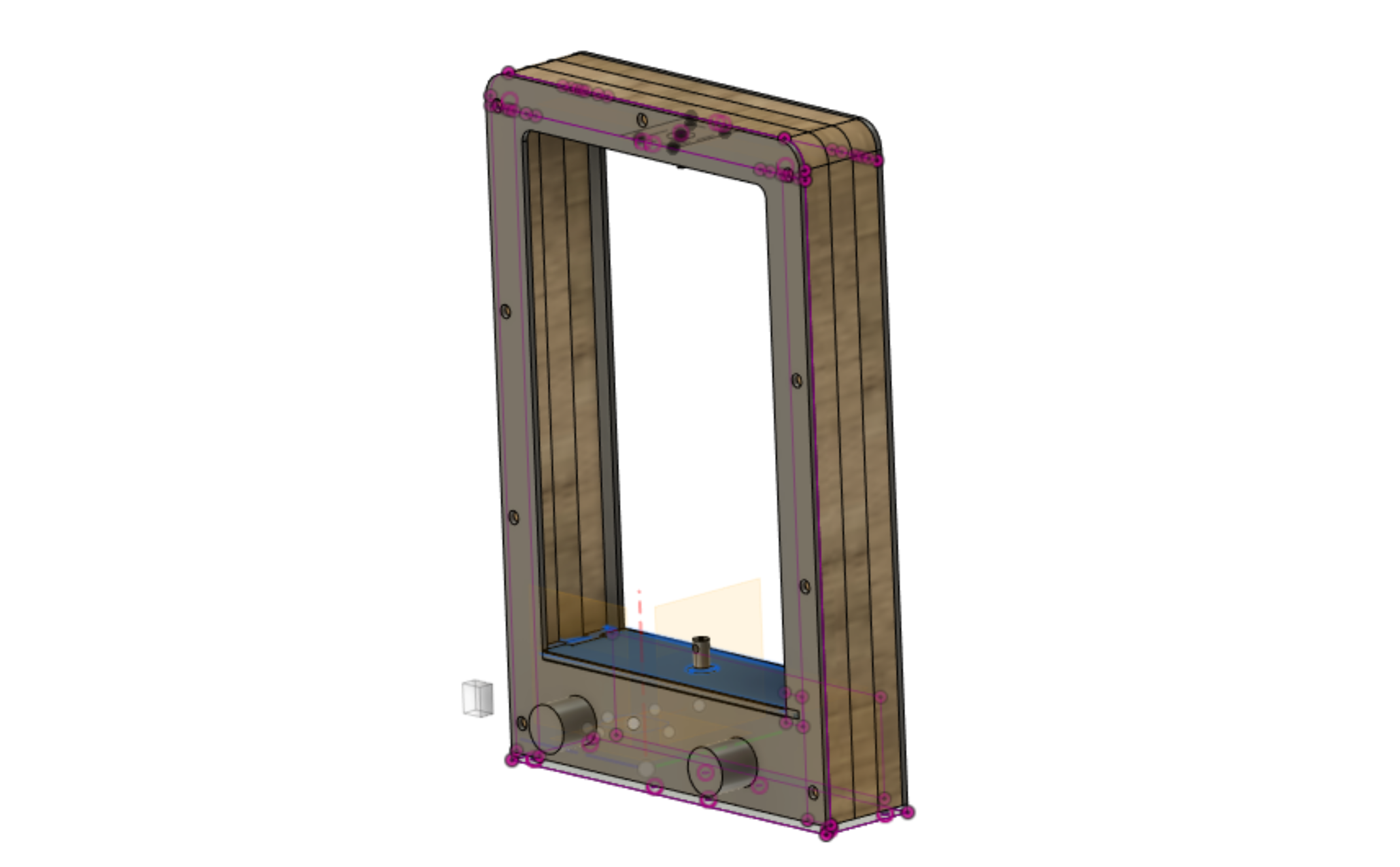
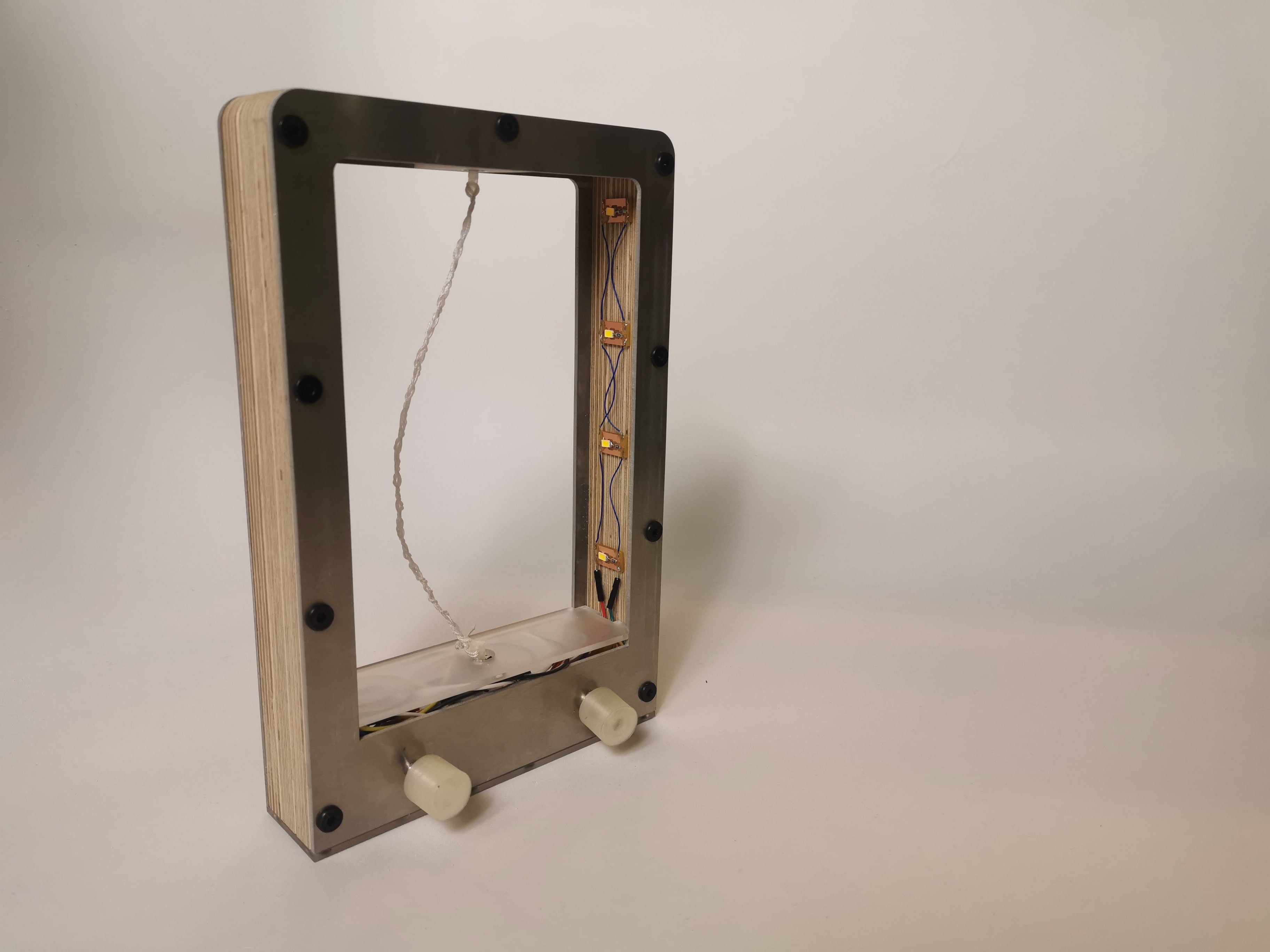
Once the PCBs were done, I designed in fusion the wood - aluminum frames and the space alocation model of each elements
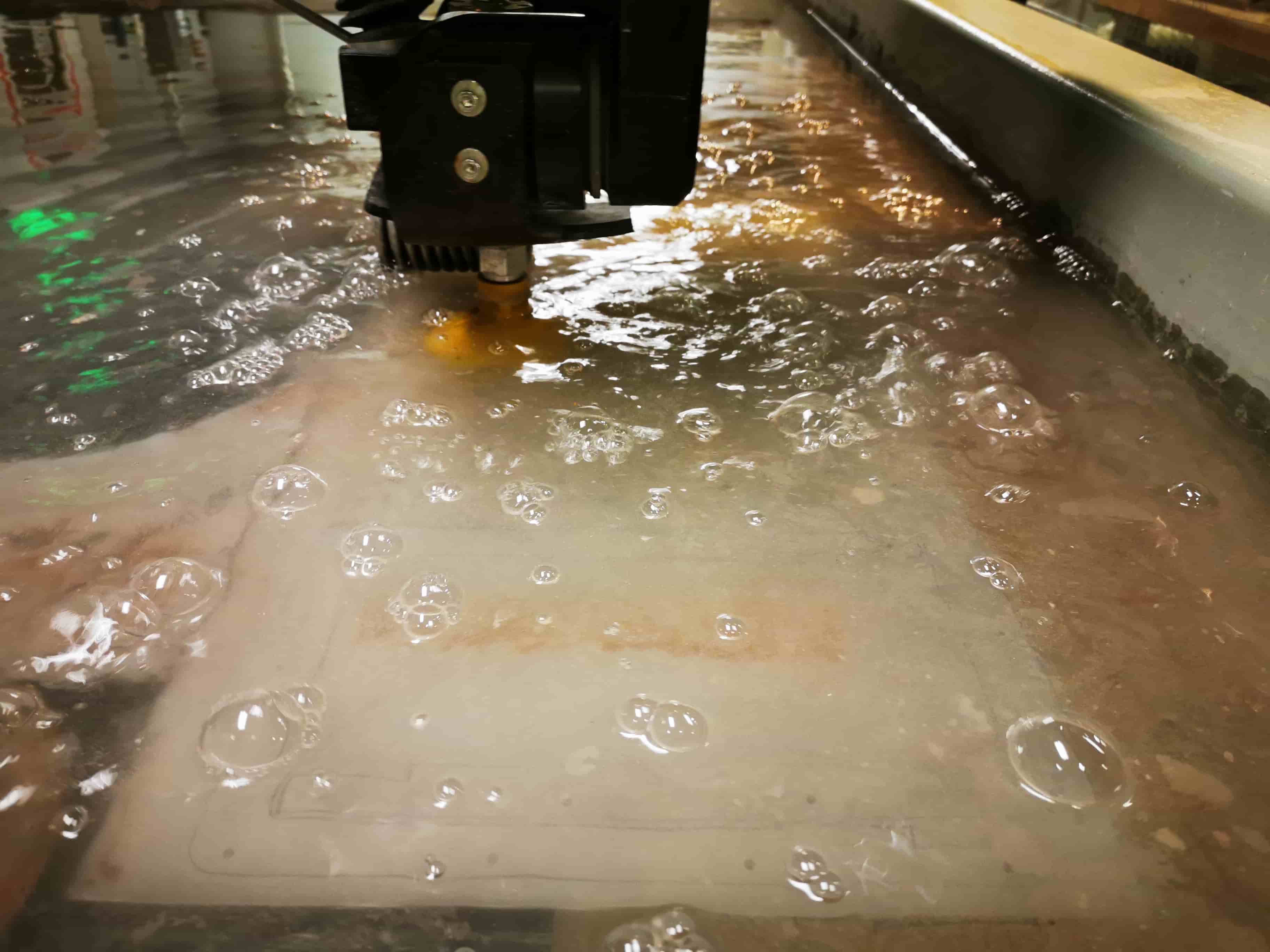
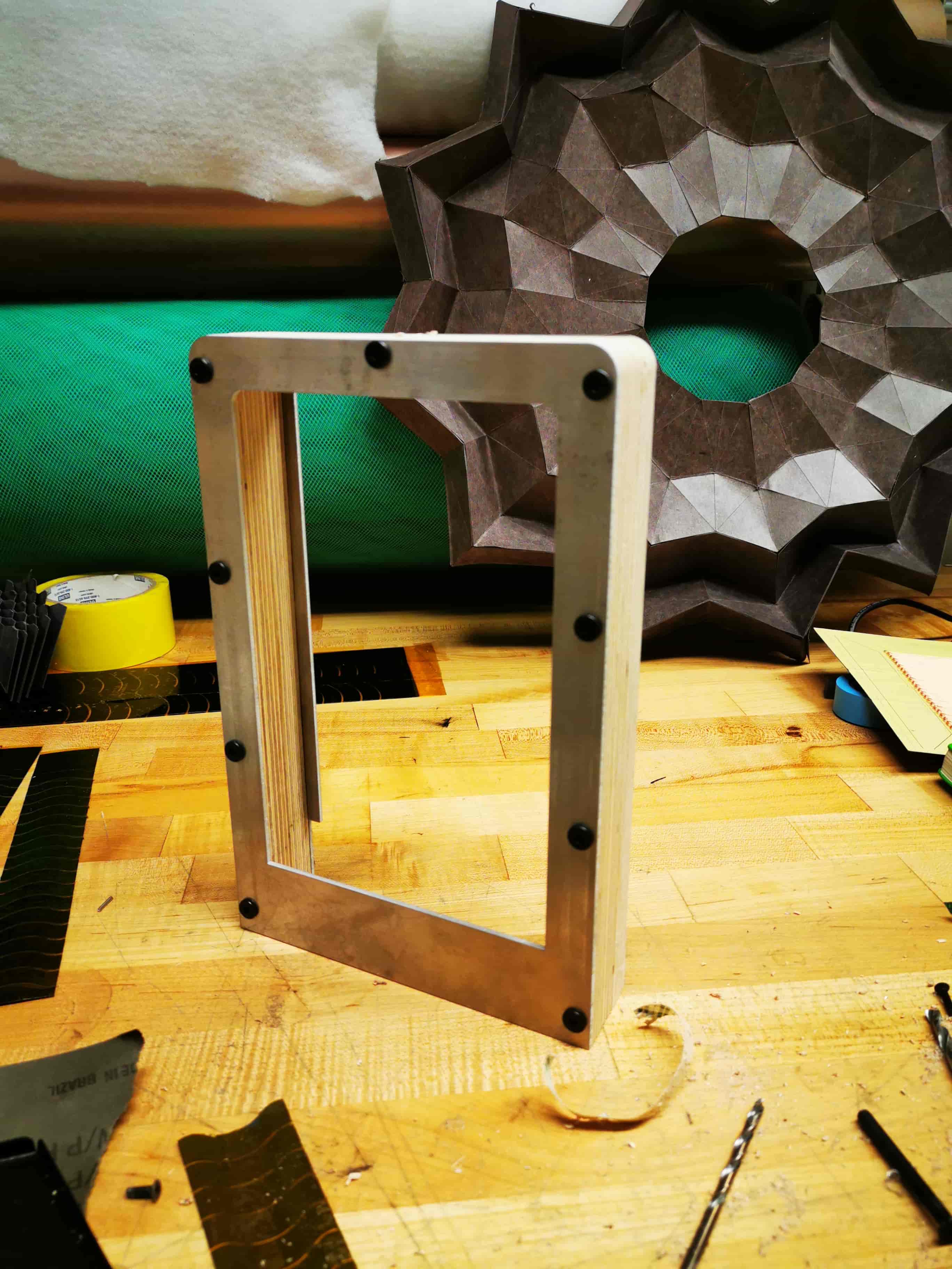
I used the waterjet to cut the aluminum frames and the shopbot to cut the wood frames. I assembled everything with black screws and the result is pretty nice.
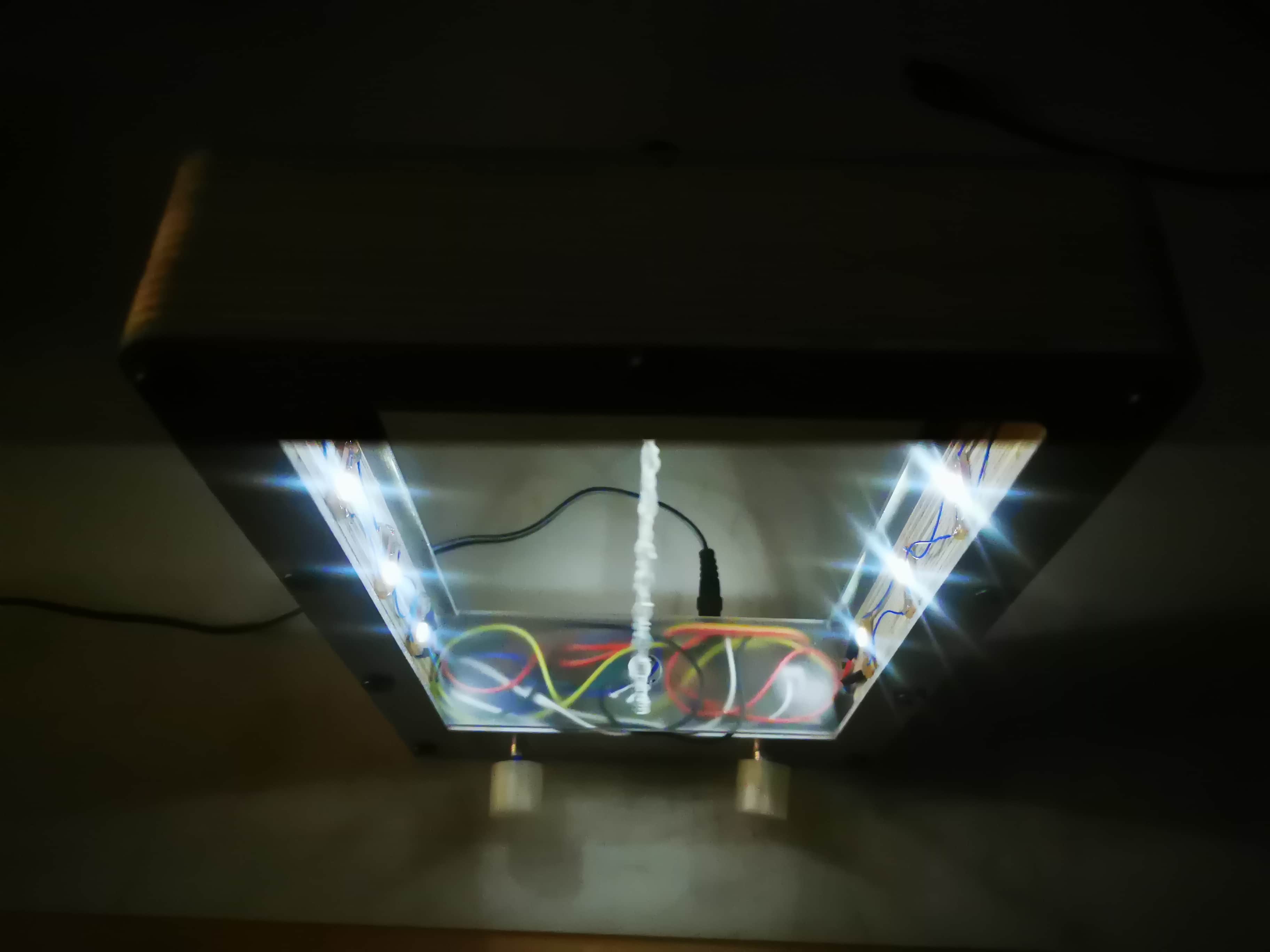
After assembly all the components, this is the final result of the lamp in use. I am looking forward to add to it more LEDs and also RGB LEDs!
Lessons learnt
Step forwards
What an intense week.... See ya!
 back to menu>