Week 9. Input Devices
Files:
This week we were asked to start going through micro-controllers and be able to read some input data from an external sensor.
SPOILER:
I have not been able to receive data
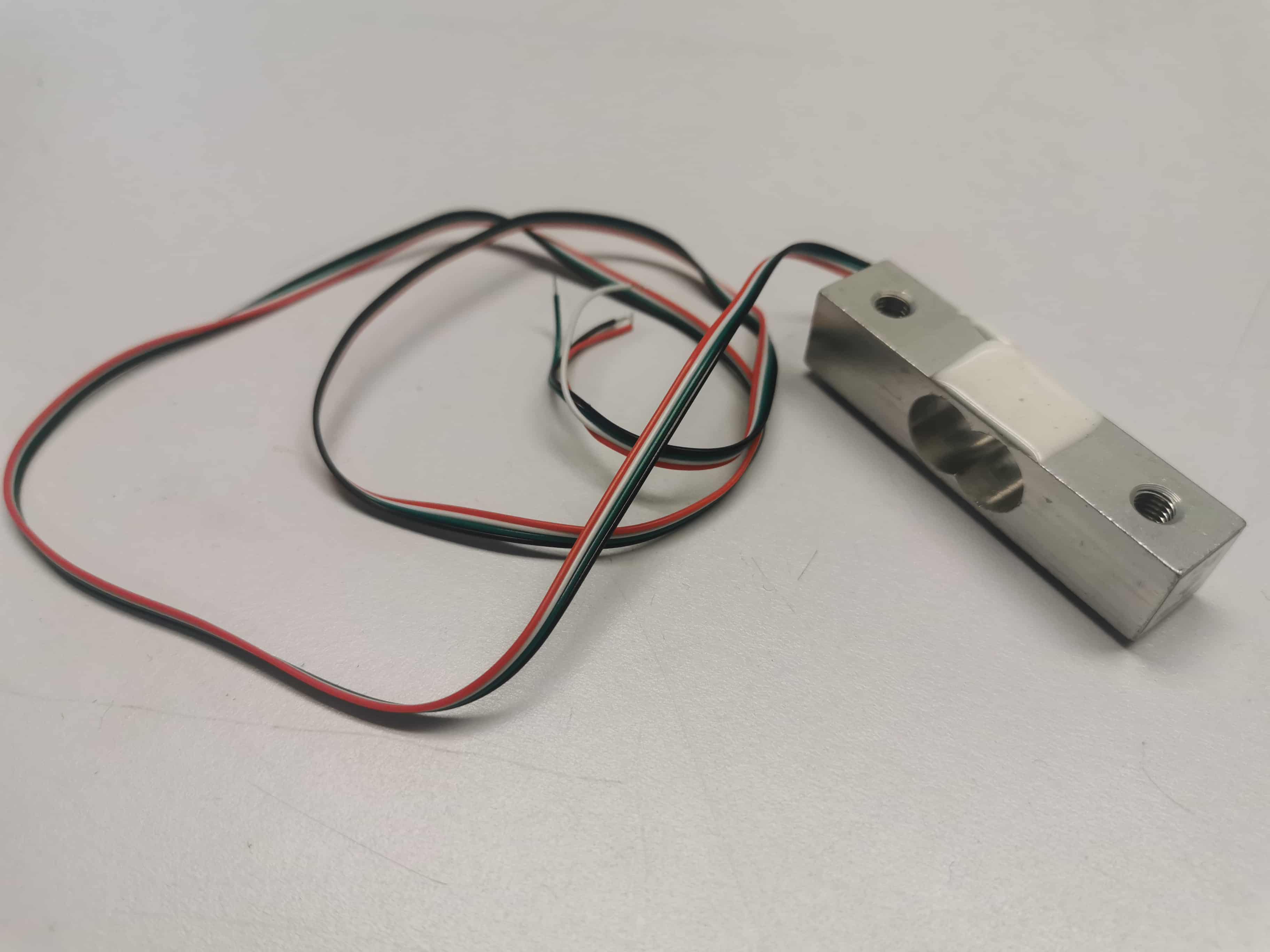
My proposal was to be able to read the analog signal of a load cell into any micro controller in order to use it as the learing curve to generate a load balance for my wind tunnel.
To be fair, I think the proposal was too ambitious to be my first input device in a diy microcontroller (diy refers to design all the schematics, route all cables, mill the 2 sides pcb, assemble the components, program the chip and be able to write a C code that reads and handle all)
I really want to thanks to Zach, Erik, Filippos and Jake for all the questions I've asked and all the help
So, what has happen....
I was extremelly excited for this week. I wanted to be able to receive data from load cells so this same wednesday I ordered two load cells of 5kg. I make the calculations to see which size of load cell I would need to use by estimating an ideal case in my wind tunnel in which at maximun speed (80kmh), I intert at maximun angle of attack a profile with a high cl (2) with a wing area covering all the section of the tunnel and a relevant length.
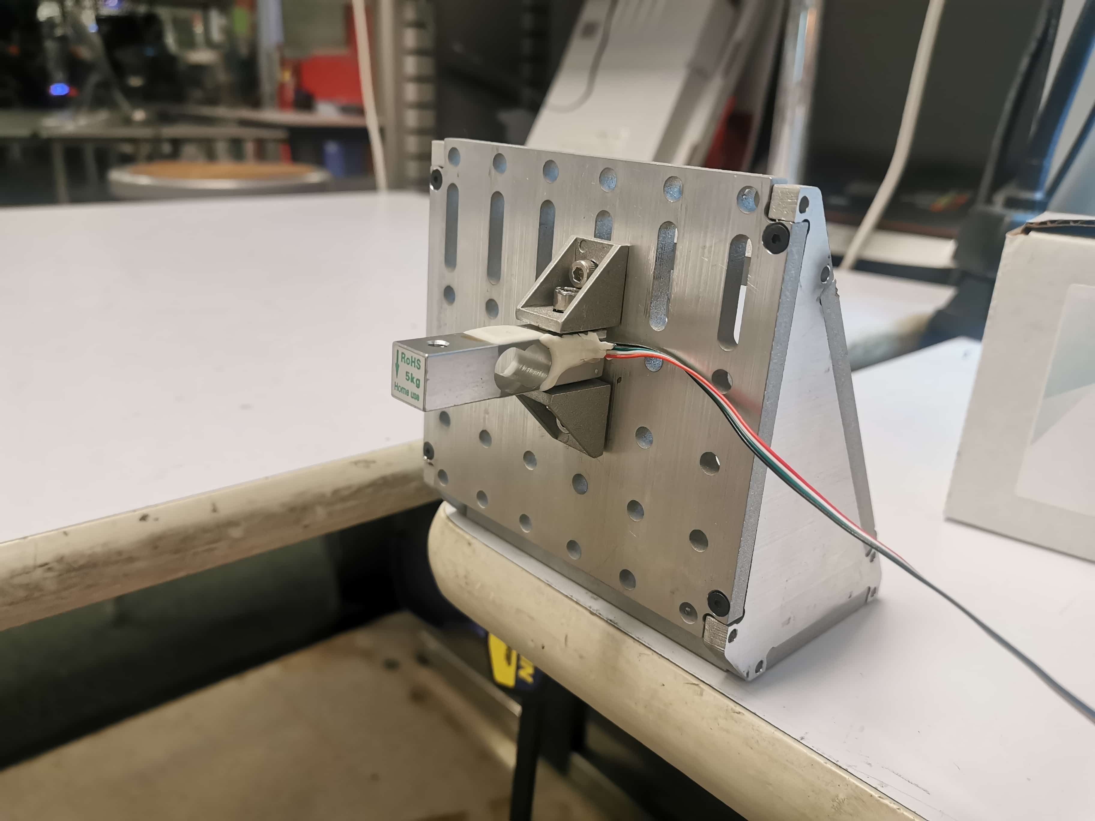
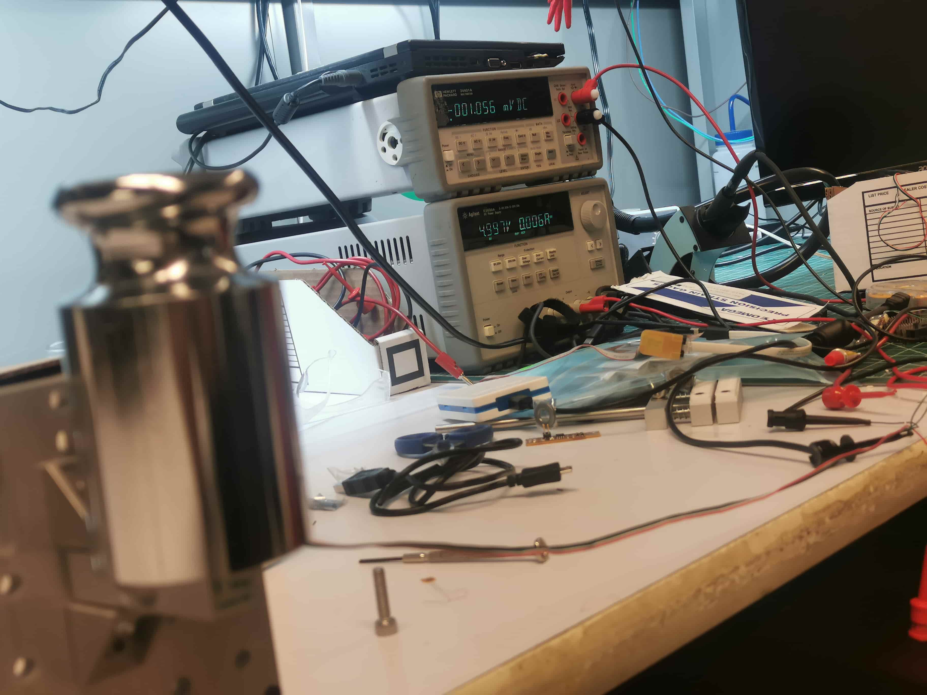
Following L = 1/2 p v^2 S Cl the result is aproximately 57 N, so with a load cell of 5kg should be enough! At a very beginning, I connected the load cell to a DC power supply and measured the output signal in order to see which was the order of magnitude. I could see that it was mV and the output signal was super linear, according with the Datasheet in wich the output is given in mV per Volt. A load of 5kg will be 5mV and a load of 1kg will have an output signal of 1mV
Here you can see how a load of 1kg gives us exactly 1mV
So as a microcontroller can read between 0 and 5V, we need signal conditioning. As a very first attempt I wanted to build a external Op Amp but internet and Filippos sugested me to use a special chip called ADS1231 that has an specific use for load cells. It reads, amplifies the value, convert it to digital and sends it to the micro controller.
He was reading the values with this chip conencted to a Polulu A Star 32 micro, that has an ATMega32u4. I decided to go into the datasheet of the polulu and replicate that board with CBA components. Also, in the same board I decided to integrate the ADS1231 so we could be able to have a unique board that has everything to read loadcells.
My experience with Kicad was so small, I only used it to replicate the Hello Echo pcb, so, thanks to Zach, I have learned tons of Kicad this week. (I had to generate footprints, introduce to local libraries, create new elements for them, change size of connectors, update netlist and components, routing, inert vias and have a 2 side pcb and export properly all layers)
After several days fighting with Kicad, I finally had the final design for the PCB that enables the ATMega32u4 speaks with ADS1231 and all the devices needed
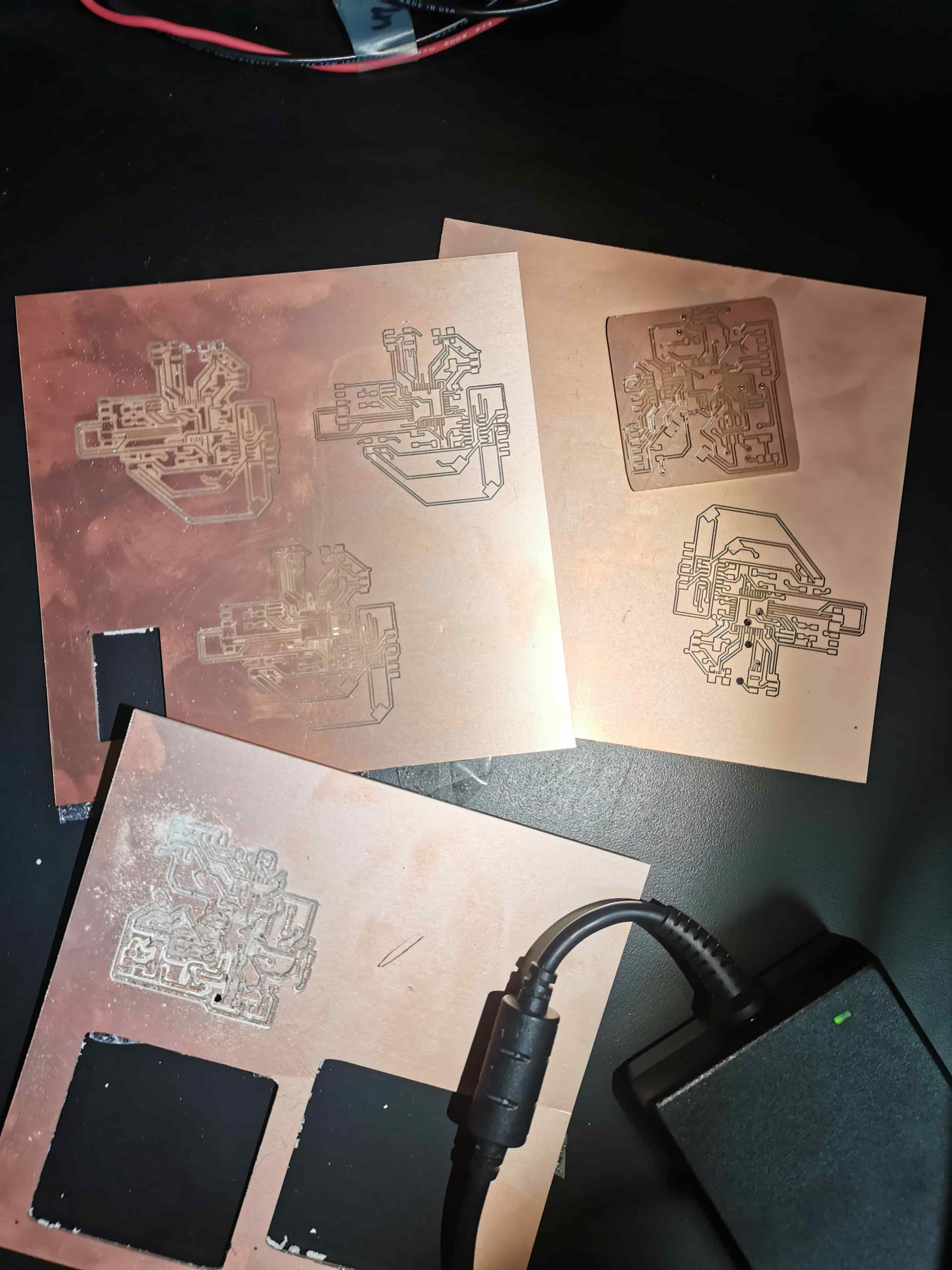
Hall od Shame
After generate the first SVG files and mill several attempts the upper layer, I decided to re-design the PCB distribution due to some traces were so tight together that I couldnt mill them. Also, some components like the microUSB has got so so tiny traces that I couldnt mill them, so I decided to have only as an external connection the FTDI cable. After puting all those implementations, this is the second design, more organized and compact.
After some attemtps, I could be able to mill all the PCB, composed by an upper layer, the vias, the border and a lower layer.
<<<<<<< HEAD =======
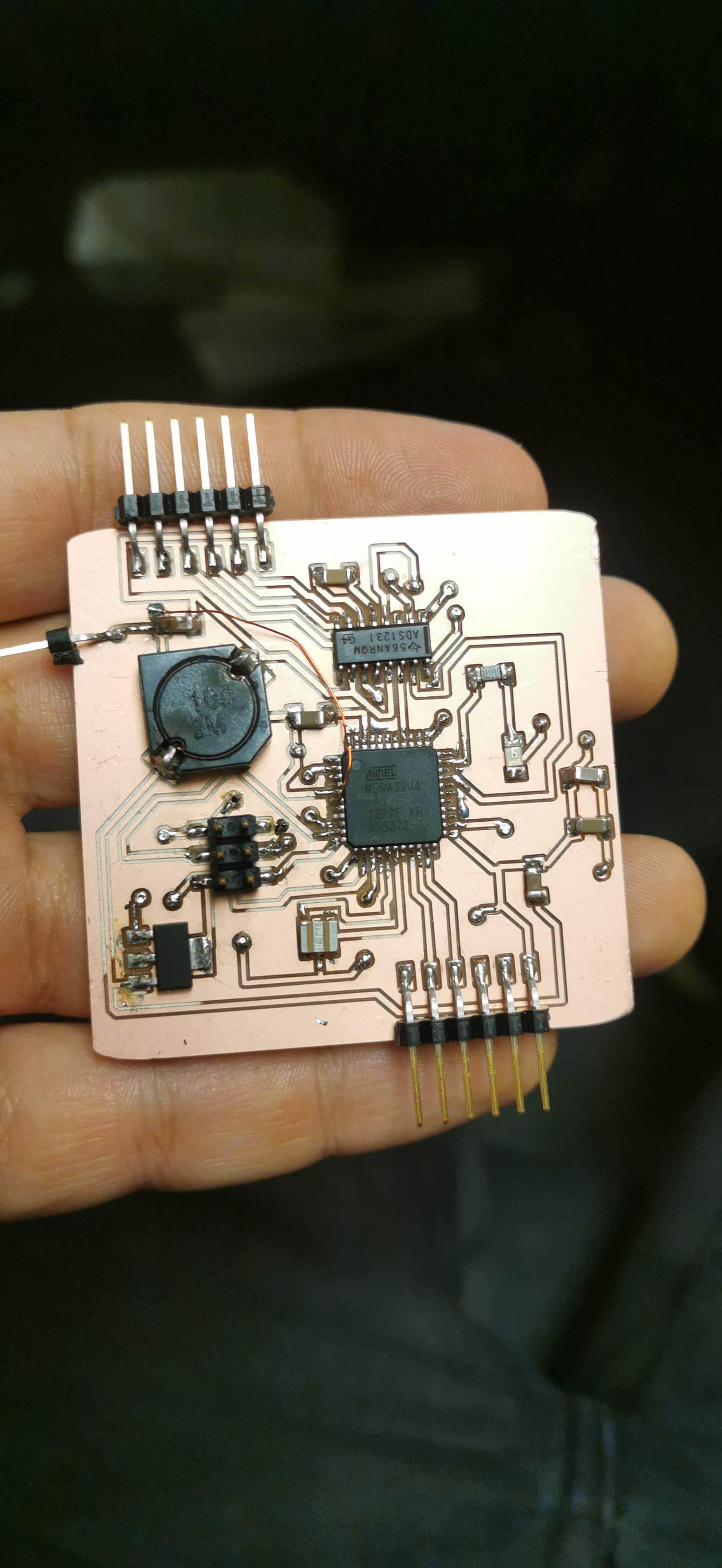 >>>>>>> 40423817ce9e2d82b169f01df8cdeb7a75715e5b
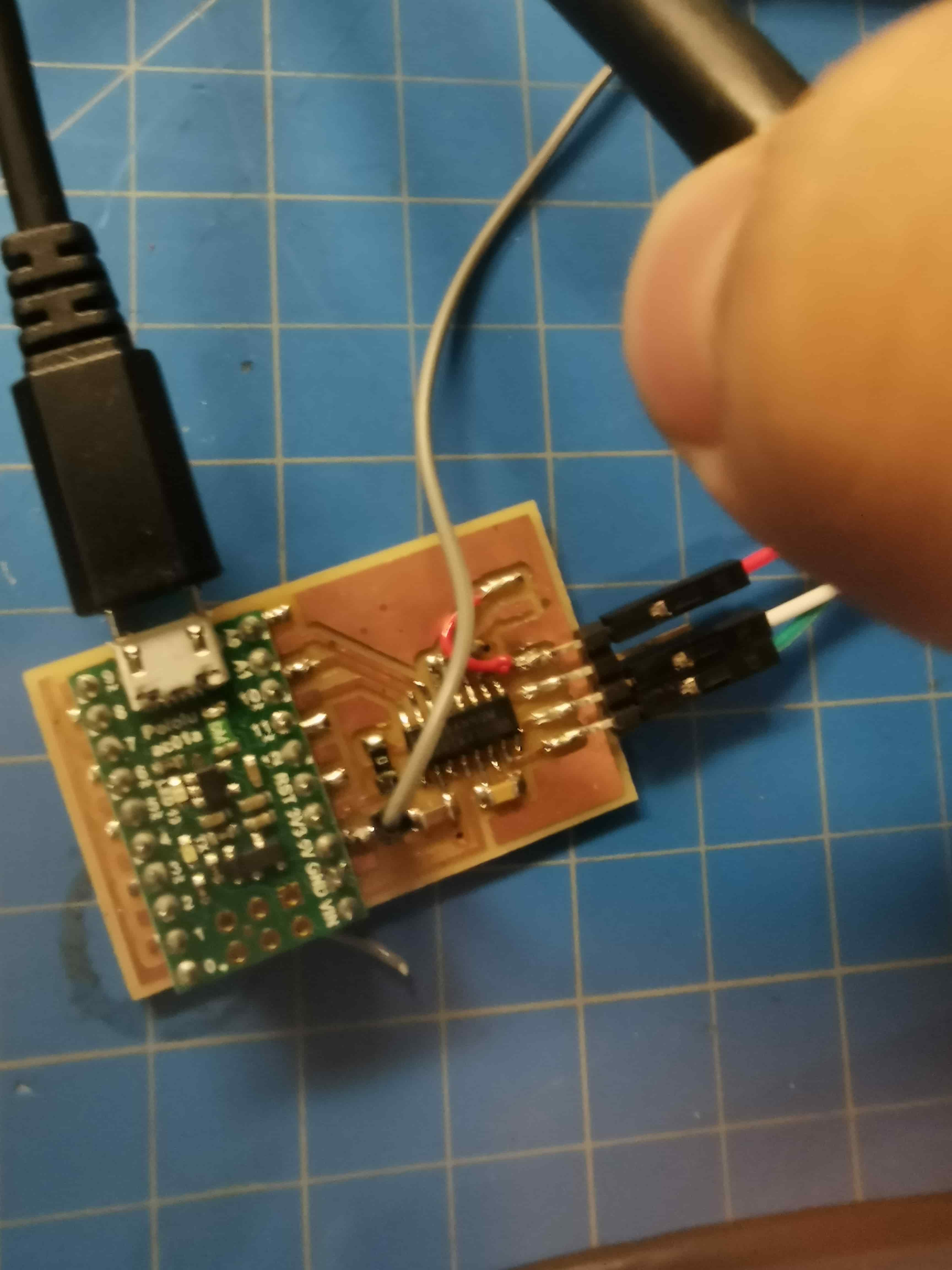
Once all components were soldered, and some repairs were made, I decided to use my programmer to program this ATmega. After changing some values of the makefile (thanks Zach again) and struggle sometime due I was receiving Error1 , I was able to program the ATmega32u4.
So our plan was to, as I am making a replica of the Polulu A Star32 micro, I could use the code from Filippos and program mine.
but..
As I took the decision of removing the USB micro, I can talk only in FTDI and seems like arduino bootliader want to talk in USB... Thanks to Erik we could load some code in the micro controller to start following a bit banging strategy. So here I am, sucked in the code
ANY suggestion will be great, feel free to contact me (aprubio@mit.edu)
back to menu>