Week 1. Introduction and Computer-Aided Design
I’m so excited to open my first content here at my page of HTMAA. This week we were asked to surf all over the CAD sw so we can decide which is the one we like the most (to work in a parametric way) and design our FINAL PROJECT PROPOSAL!
One of the reasons I came here was to be able to think further and not only in Aerospace implements… but as a final project I want to make my own tiny Smoke Wind Tunnel. I consider it’s a really cool and fun device. It is so complex to have accurate results but it has a huge educational value. To see streamlines with your eyes is something unusual!
/////////////////////////////////////////////////////
The main theoretical estimations are stream flow calculations based on Bernoulli and Continuity equations. A wind tunnel is just a composition of a Diffuser and a Nozzle joined by a fixed diameter pipe.
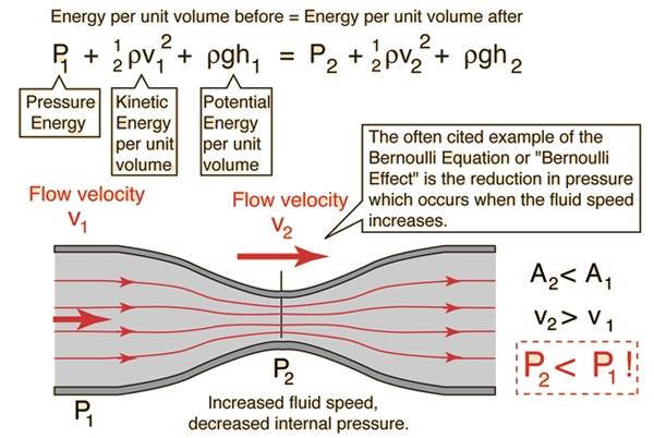
Continuity equation gives us the following equation:
What it is looking for is to have as much velocity as possible inside the duct (v2) but also being realistic. We want to put stuff inside so it has to be not so tiny so we can watch it better and design mockups in a big scale to be as detaillist as possible!
To start to make tangible this idea, let’s start to dimensionalize it with stuff I’ve founded in the lab.
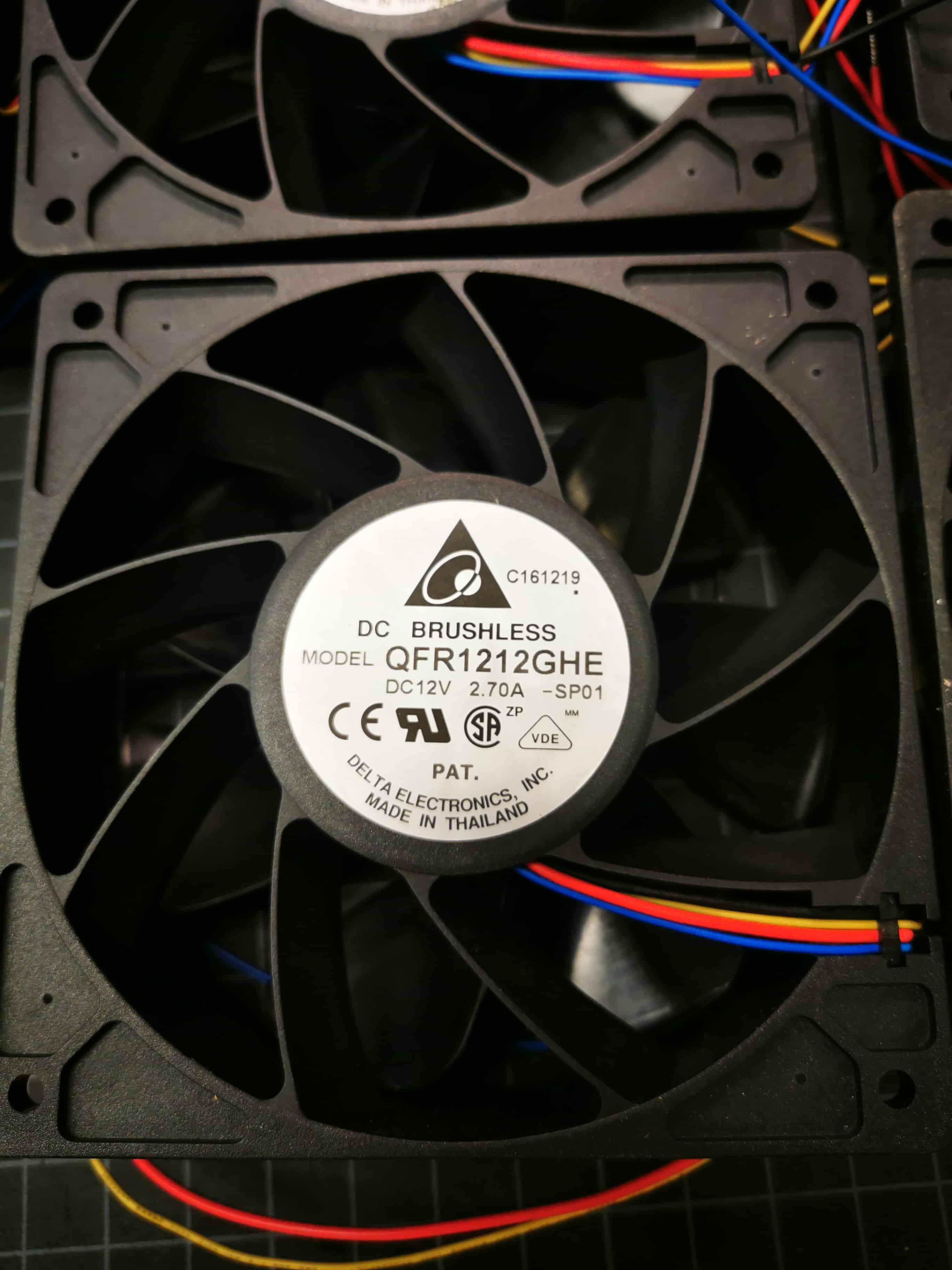
I took a box with 12 of the above dc brushless computer fans model QFR1212GHE SP-01. I decided that the suction plant of the wind tunnel will be composed by a 4x4 array of those guys. Looking the provider specifications, I’ve found that :
As the Air Flow is 2.89 m3/min, doing the following calculations, we can estimate the linear velocity of a square based area of the dimension of the fan (120mm x 120mm). This velocity calculation is extremely important in order to calculate the final velocity of the test area.
Each fan is giving us 2.89 m3/min. To estimate velocity through area we can use the mass flow equations.
Now to estimate linear velocity based in a desired area (due to my final are of suction will be a composition of square units of area, lets assume that the air are which we are expulsing air is the square area of the fan which is 120 mm * 120 mm (0.0144m2).
With this design input, assuming we are going to use an array of 4 x 4, giving some mm as gap, the wider length of the diffuser and nozzle will be 550mm.
Its is gonna be estimated the duct section based on the maximum velocity we can reach in it. Ideally it could be 80km/h (aprox 22m/s) :
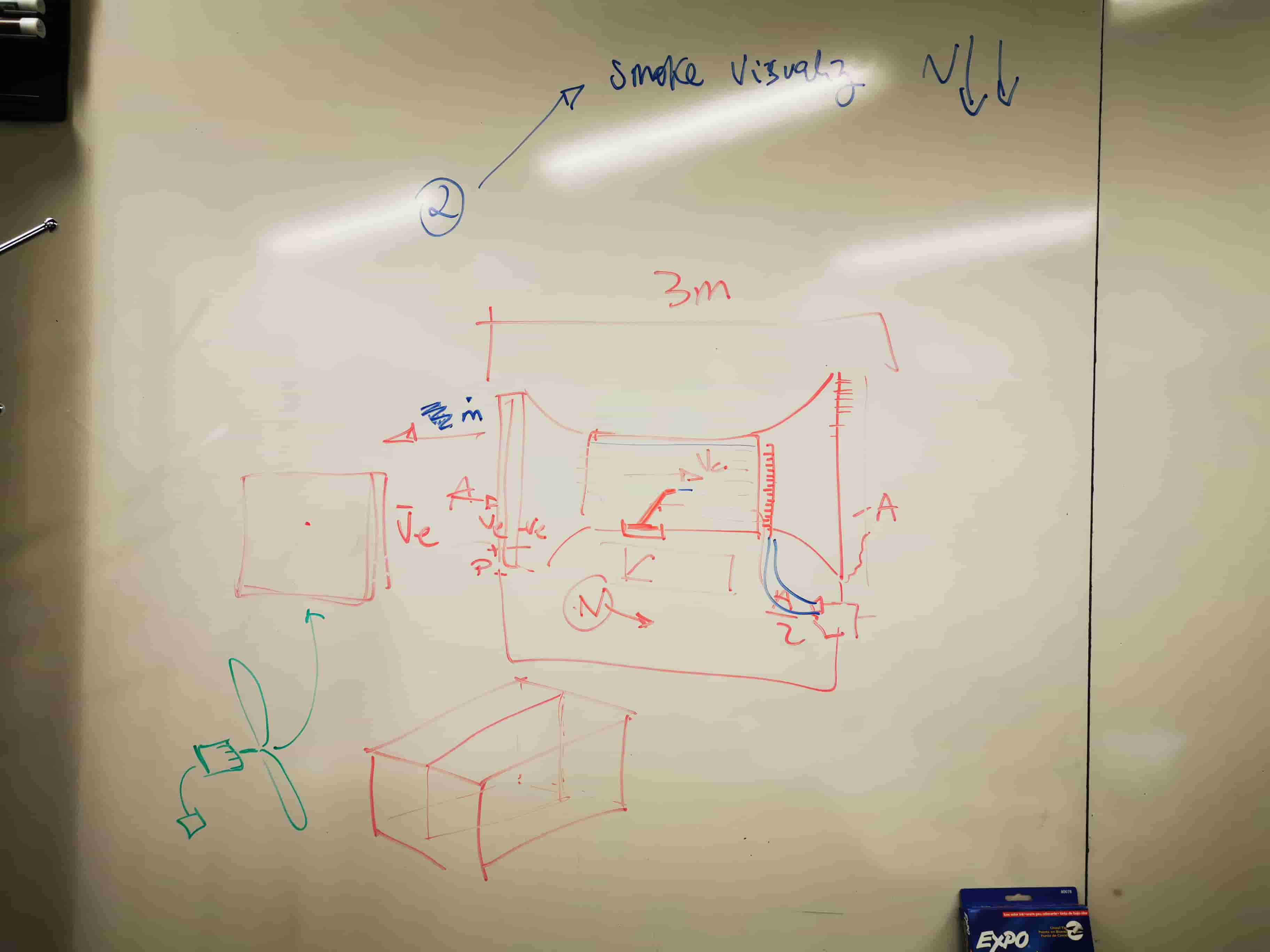
In order to make it easier to manufacture, Its been set that each side will be 300mm. The design process, once estimated the distances, has follow those sketches.
Pase 1_ Whiteboard Sketch
Phase 2_ A little more detailed sketch with some new ideas
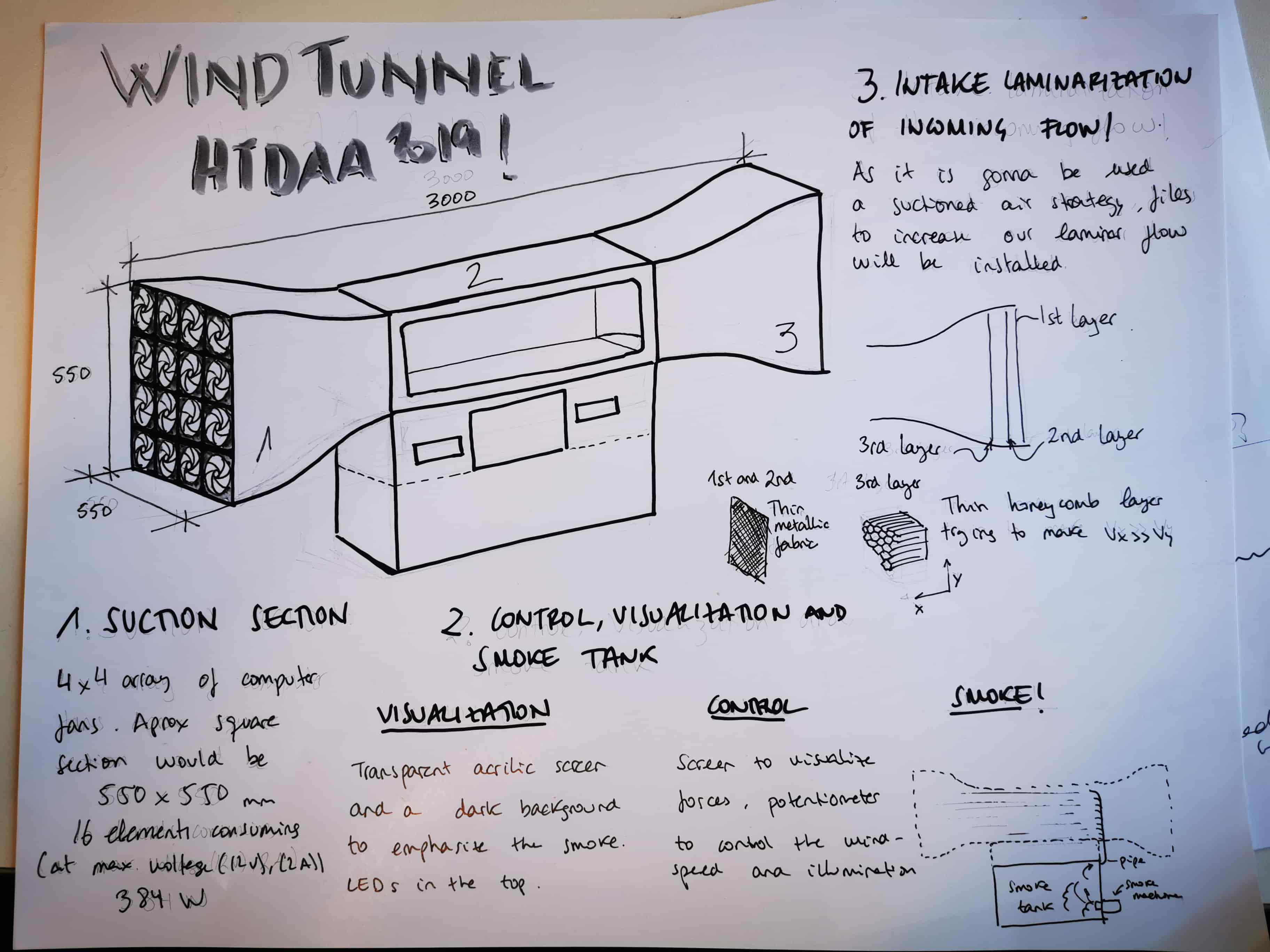
As it can be seen, it is composed by 3 main stages.
1_The Air ducts, composed by a nozzle, a diffuser and a fixed pipe in which experiments will take place.
2_Control. Zone in which we will be able to control the velocity of the air as well as (hopefully) has some control item to measure and display aerodynamic forces of the item to test.
3_Smoke container. Composed by the smoke machine, which will feed this container with smoke and a small pipe with which will displace smoke in a longitudinal array inside the duct.
Phase_3. Time to CAD!
After so so many years using Catia (close to 8 years…..) my actual situation has forced me to change CAD tool! I decided to use Fusion instead FreeCad due to the CAM feature it has. I’ve seen some limitations compared with Catia but it has been fun to change and adapt to a different SW.
As a first attempt, I designed the nozzles and diffuser optimized for a better air behavior.
As bigger radius the better. But this design led us to a problem! It is not trivial to manufacture in a fast way with a 3 axis CNC miller from a flat perform those shapes. And the most critical part is not to generate them (living hinges would work!) Is to find a metallic profile for the edges with this shape.
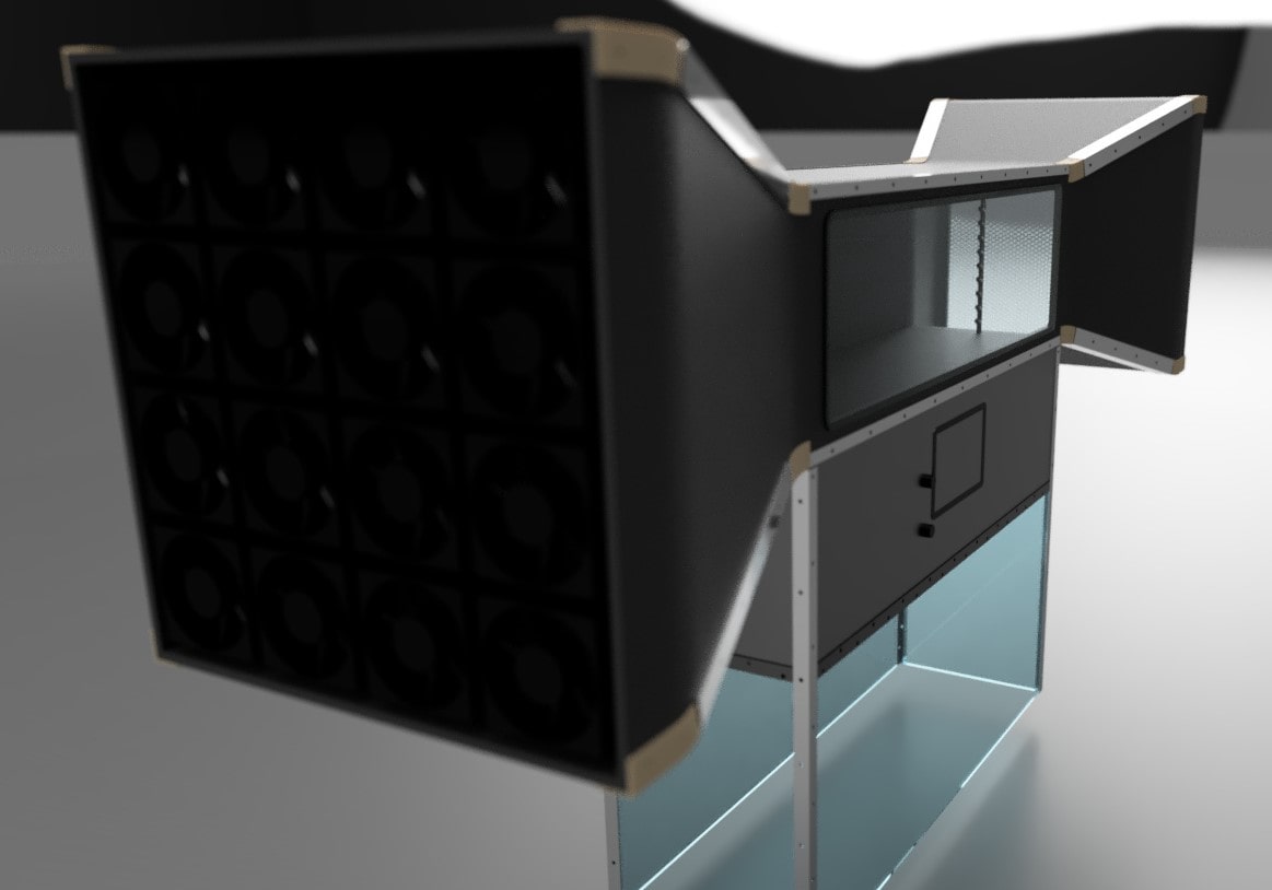
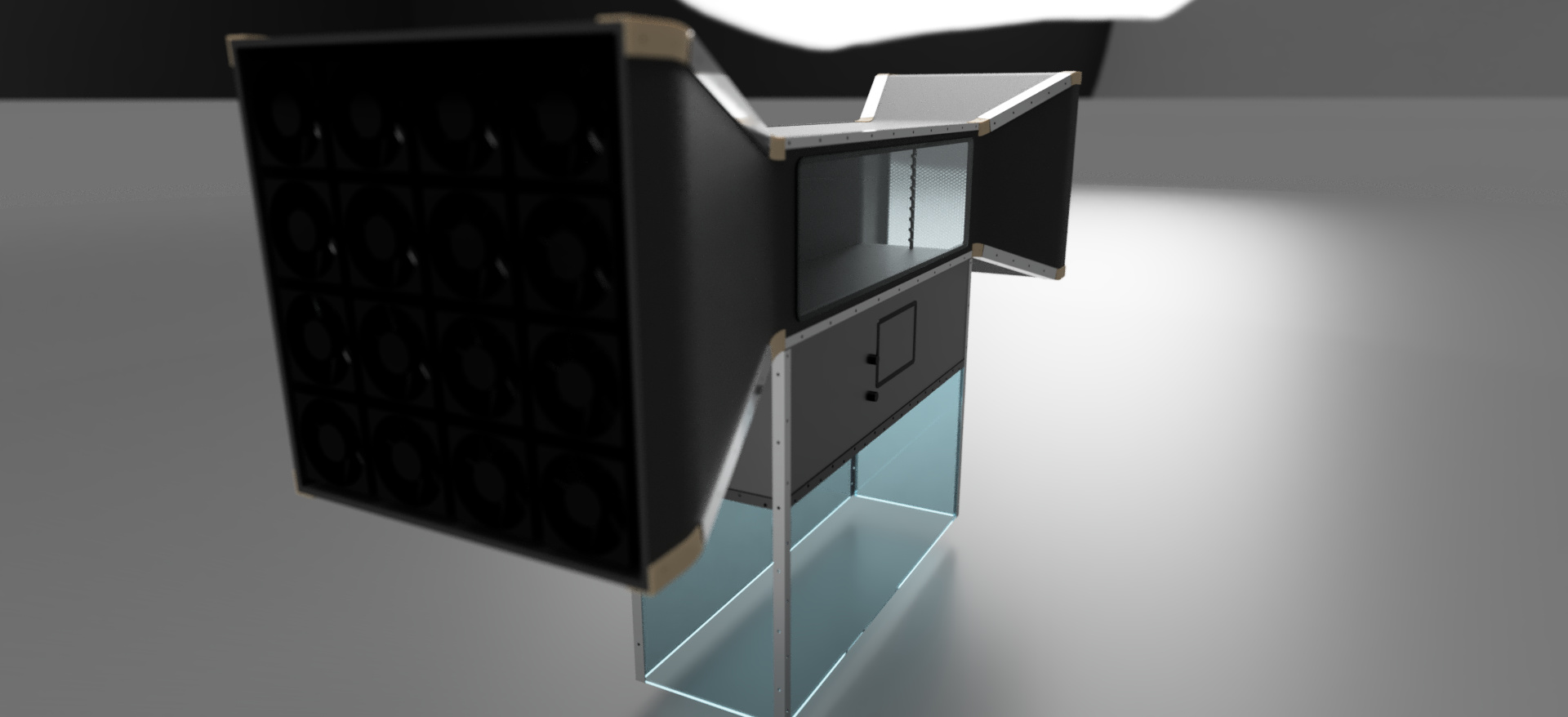
For that reason, it has been redesigned to this geometry. This is the actual version of the wind tunnel! After a session of detail CAD, this is the final model that has been decided to manufacture:
Also, those are the final renders that fusion has done. Hope you like it!
 back to menu