learning electronics
This week, I decided to get through the project a little bit differently - I'm tired of feeling lost and confused with no context for what each step is actually doing as was the case with week 2. So I followed the rabbitholes and questions that came up until I felt like I understood the electronic components enough to move on. below is a somewhat incoherent list of things that stood out as important basic background info for circuit design this week:-
packages are the literal packaging that goes around each component part. there are different styles of each with different surface-mount technology for example, QFN - quad-flat no-leads
- surface-mount technology (SMT) vs. through-hole technology - different methods for producing circuits. we are building SMT circuits
- Small-outline (SOP) - I think this is what we're working with for the most part. SOIC (small outline IC). pins on two sides
- Quad Flat Packages (QFP) - pins on all four sides of tiny chip. but there's also the quad-flat no-leads (QFN) which looks like you sanded off all the legs of the QFP
- Ball Grid Array (BGA) little black chips with balls of solder on the bottom which are sometimes connected directly to the IC die. not something you can solder on your own - usually assembled with pick and place and reflow ovens
- potentiometer - basically a voltage divider. it can be two resistors in series that have a third terminal between them so a single input voltage can be split into two smaller voltages
-
transistor - semiconducting device used to amplify or switch electronic signals
- BJT (bipolar junction transistors) have three terminals: collector (C) , emitter (E), and base(B) two different types: NPN (arrow pointed out) and PNP (arrow pointed in)
- MOSFET three terminals: source (S), drain (D), and gate (G) n-channel(turns on when you apply a positive voltage) vs p-channel (turns on when you apply a negative voltage)
- opamp (operational amplifier) - high-gain electronic voltage amplifier. it's a building block of analog computation but is decreasing in popularity now because most ICs have it built in
- resonators and crystals are used to generate clock signals in circuits. a resonator is just a crystal with two capacitors on each side.
-
communication protocol: there are a lot of different communication protocols out there, but most the time can be split into two groups: parallel (requires data buses which are a group of wires each carrying one bit of information and the sum of their delivery is the whole message) or serial (streams one bit at a time accross one wire to communicate messages sequentially)
- examples of serial protocol: USB (universal serial bus), Ethernet, SPI, I2C. the biggest different between these protocols is whether or not they are synchronous
-
serial communication
- Baud rate: the rate at which data is transfered over a serial line in pits-per-second (bps). value is used to know how long the transmitter holds the serial line and what period the receiver should sample its line at. can be set to any reasonable value as long as all devices are set to the same one. typical baud rate is 9600 bps and you won't see it exceed 115200
- data chunk: the meat of the serial packet which contains all the data that you want to actually receive. can be set to any length between 5 - 9 bits - obviously 8bit is most common, but in some cases 7-bit can be faster. the two serial devices must agree on character-length on the "endianness" of their data - ordered in most-significant bit (msb) to least or least-significant bit (lsb) to most. default is usually lsb first.
- synchronization bits: the start and stop bits around the info packet - the device will always be idle at 1 so start bit will always bring line to 0 and stop bit will bring it back to 1. stop can either have 1 or 2 bits
- parity bits: low-level error checking so the serial devices need to agree on what their parity is and then the last bit will always set the message to have that parity. but it's not used frequently since it take time and requires both devices to implement error checking
- example of serial communication: 9600 8N1 = 9600 baud, 8 data bits, no parity, 1 stop bit. Note that, at 9600 bps we're sending 10 bits for each byte of data so it's actually running at 960 bytes per second (because of the start and stop sandwhich bits)
-
Serial peripheral interface
- there's only one side that generates the clock signal (CLK or SCK - serial clock) and that side is the master. data going from the master to the slaves move along MOSI line (master out / slave in) which is moving in the same direction as the clock. The clock is continuously generated, so when the slave wants to return data it follows MISO (master in / slave out)
- the clock that the salve returns data on is "prearranged" so the master must know how much data and when the slave wants to talk - this isn't usually an issue since different messages can be configured to udpate the master's expectations
- SPI is "full duplex" - meaning different lines for send and receive) so depending on the device, it may be possible to do both at once
- Slave Select (SS) is another line that "wakes up" the slave when it needs to receive or send data. if you have mulitple slaves then this line is used to select which slave you're talking to. it's held high (i.e. active low) so that pulling a slave down activates it. but can you have mulitple slaves active at once??
- you can hook up mulitple slaves where each has it's own slave connect - or daisy chain them together so one's slave output is another's input (this is uaully only nice for systems that don't receive data back)
designing the board
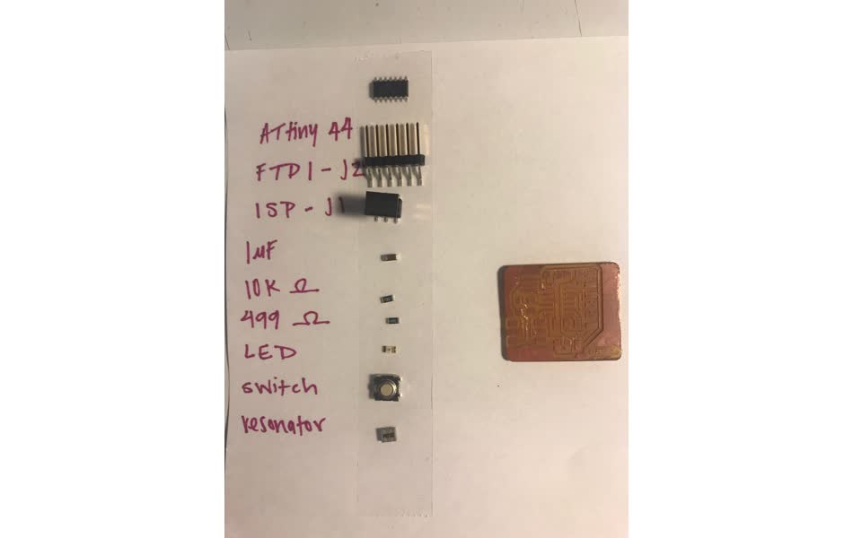
I found this schematic tutorial to be helpful. I downloaded the fablab eagle library from here and began importing all the parts my board would require. Using Neil's board as a reference guide and the fablab inventory, I found all the parts on digikey and their corresponding name in the fablab library.-
resistor
- pull-up resistor for the reset pin on the ATTiny44. a pull up resistor is used to make sure that the pin is always positive (or always negative if a pull down resistor). If you have a pin unattached then it's value could be floating high or low and you can't get a realiable read from it so adding a resistor connected to either ground (pull down) or the supply voltage (pull up) will gaurantee a value when no logic current is being supplied.
- value should typically be something that's anorder of magnitude less than the input impedance of the MCU pin (found in datasheet) - usually around 10k ohm.
- some MCU pins have internal pull up or pull down resistors - check the datasheet
-
resonator
- keeps time for the communication protocol
- clock is an oscillating signal that determines when a device will check for signal - depending of the device (check data sheet) the receiver will look at the data wire when the clock is rising (low to high) or falling (high to low)
-
ATTiny44 microcontroller
- computing power house of the chip
-
capacitor
- filters out any noise in the power supply
-
ISP header
- connector for programming the chip with the FabTinyISP from week 2
- switch (button)
- green LED
-
current resistor for LED
- Knowing the maximum current through the green LED is 10mA and the voltage through the circuit is 3.3V, the resistor should have resistance: R=3.3V/0.01A = 330 ohms. The closest resitor to that value in the fabinventory is 499 ohms, so I went with that one. Also, comparing to Brian's board from week 2, thep green LED has a 499 ohm resitor.
Drawing the board schematics was rather straight forward once I had all the parts and could follow Neil's original board layout
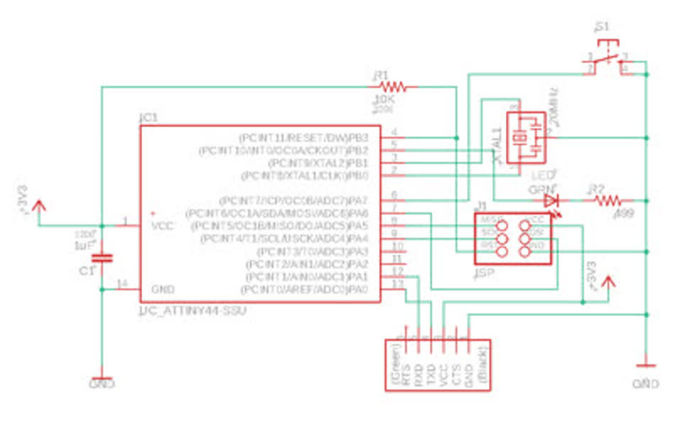
Then I needed to actually design the layout of the board. Sparkfun has another good Eagle tutorial that I relied on.

fabricating the board
finally, it's time to mill the board. I exported the eagle layout to a png file using the python script with instructions described in the manufacturing section here. Then sent the png to mods and milled it the same as week 2.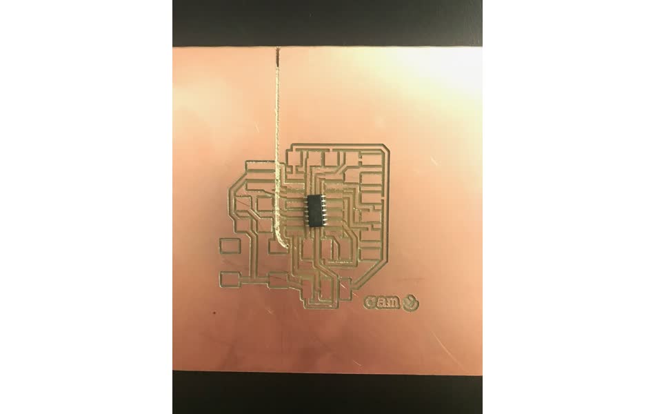
. . . but this time the traces came out waaay too large - one ATTiny44 nearly fits on a single pad. and the cutout outline didn't match the size of the board so it cut a large line right down the middle.
The problem was the dpi (dots per inch) setting when loading the .png file to mods. mods calculates the real distance to mill based on the number of pixels in the image, so you need to calibrate the dpi. to do so, I measured the ground pad for the button in Eagle to be 2.29mm = 0.09 inches. Then in imageJ, I measured the same pad to be about 273 pixels. Therefore, dpi = 3033.
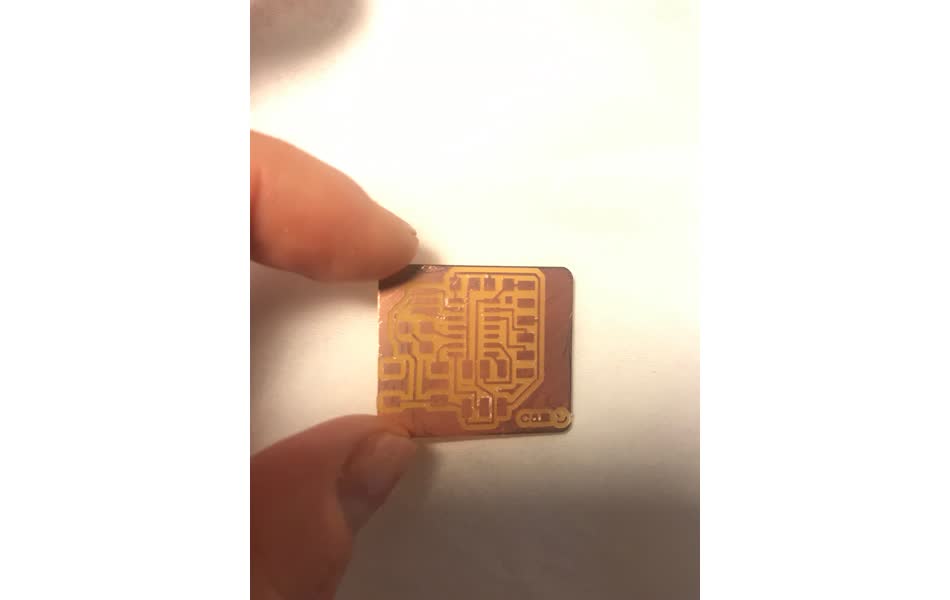
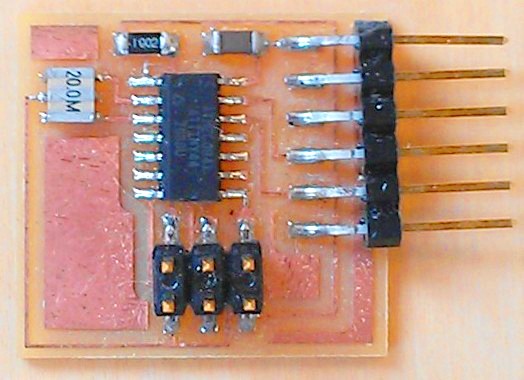
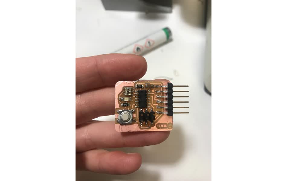
finally milled the right size traces, collected all the relevant components, and ready to solder
and finished!
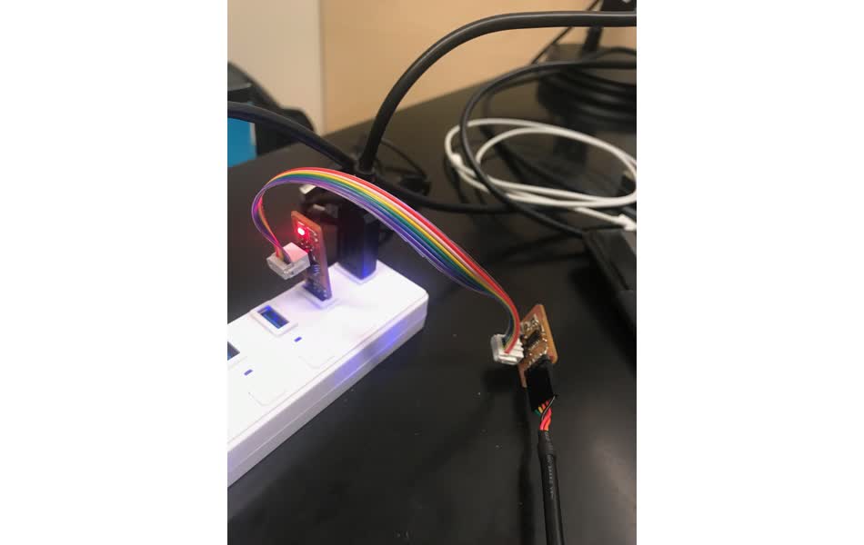
programming
I plugged to programmer and board into my macbook and it doesn't show up at all. But then plugged into the linux machine and it does - even with the usb 3.0 hub so the issue with the macbook must not be the speed.make -f hello.ftdi.44.echo.c.make ran fine, but then I got a rc=-1 error when trying to run sudo make -f hello.ftdi.44.echo.c.make program-usbtiny-fuses
I went back to the lab and Zach helped me realize that the ATTiny was soldered backwards - thanks zach! came back and then the program-usbtiny-fuses command worked once but then when trying to run program-usbtiny I get the rc=-1 error again. then trying to run fuses again I get rc=-1 error again ...
the issue is the crystal. program-usbtiny-fuses sets up the mcu to no longer listen to its internal clock and instead switch to the clock on the crystal. but my cyrstal wasn't soldered correctly - the ground signal was accidentally connected to the mcu as well.
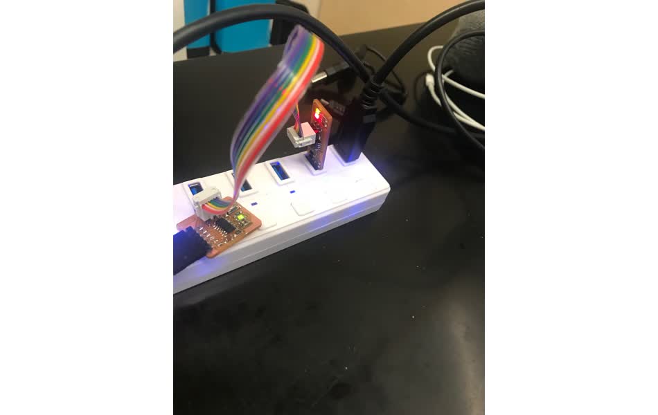
so fixing the soldering worked! plugging in the usbtiny after made the green light turn on on the helloworld board. and the green light turned on on the programmer
finishing the make commands to get the programmer running - the next step is to use the python script to open up a little gui interface to the serial port and see what the helloworld chip has to say.
** note:: python script dependencies: python-tk and pyserial
so I'm sending data to the board, but it doesn't seem to be making it there ... I can press the button and receive a list of what was typed but it never says I typed anything . . .