CAD Designing
Back in week 3, I designed and printed a rough draft for my clothing rack, but I wasn't really happy with the result. Jake gave me a great tip after he saw my model -- design something while keeping in mind that it's being subtracted from a sheet of wood. It seems rather obvious, but helped me switch perspective from the stacking-blocks-of-wood mindset I was in before to cutting the structure out of the sheet.So with a new blank slate -- I know that I want a rack, a shelf above the rack for sweaters, and a shelf jsut above the ground for shoes. I'd also like to do something creative with the side panels to be able to hang things like scarves, belts, a mirror, etc. . .
model V1
I searched the fabclass custom google search for inspiration from previous years and came accross Joelle's bookshelf from 2013 - I like the simplicity in the design and how straight forward it would be to mill from the slabs.I created a similar design in Fusion 360.
Before milling, I tested out the design by laser cutting a 1:10 scaled version on 1/64" thick plywood. Scaling the design in Fusion 360 was very straight forward since I had defined the material thickness as a parameter and the slots could scale accordingly {{. . . foreshadowing . . .}}
annnd it quickly became clear that this model would need to be abandoned .. it's terrible unstable.
I suppose I could have saved it by tightening the joints by optimizing the material thickness in Fusion to account for the kerf with this plywood material - as opposed to using the 0.3mm estimate I took from week 1 when cutting cardboard. But I wouldn't want to waste material making the same adjsutments on the ShopBot and taking a second look at the design there's no way it's structurally osund enough to hold heavy clothing.
model V2
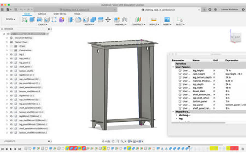
Jake designed these cool standing desks for his office space in CBA. They feel stable enough, so I decided to mimic the perpendicular legs and rim beneath the table top to add some structure to my clothing rack.This model was more complicated than the previous, but after a few hours of messing around, I felt like I was finally getting that hang of parametric design . . .
Adding cutouts to the side panels
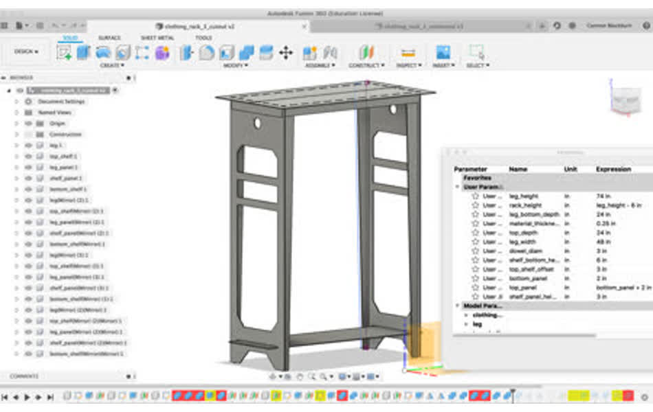
With the model done and only a day behind my intended schedule, I'm ready to lay out the model into 2D cutouts to send to the laser cutter. Unlike clothing rack V1, I drew the sketches in Fusion 360 for only a fourth of the model and then mirrored the bodies in two directions. This made me feelf ancy in Fusion, but I only know how to export .dxf from sketch objects and none of the sketches have the full body surface. So, following Jake's workflow, I decided to explore Rhino for "make2D" command.
{{~queue two day detour~}}
Ben helped my download Rhino. Then Ben took one look at my model and helped me see how broken it truly was . . .
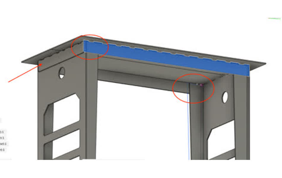
First, most obvious are the misaligned corners at the base of the top shelf. This is an issue unique to the model with the side panel cutouts, but I can't pinpoint where exactly it broke along the way. Then, the "support" panels are along the depth of the legs are actually doing much for support.
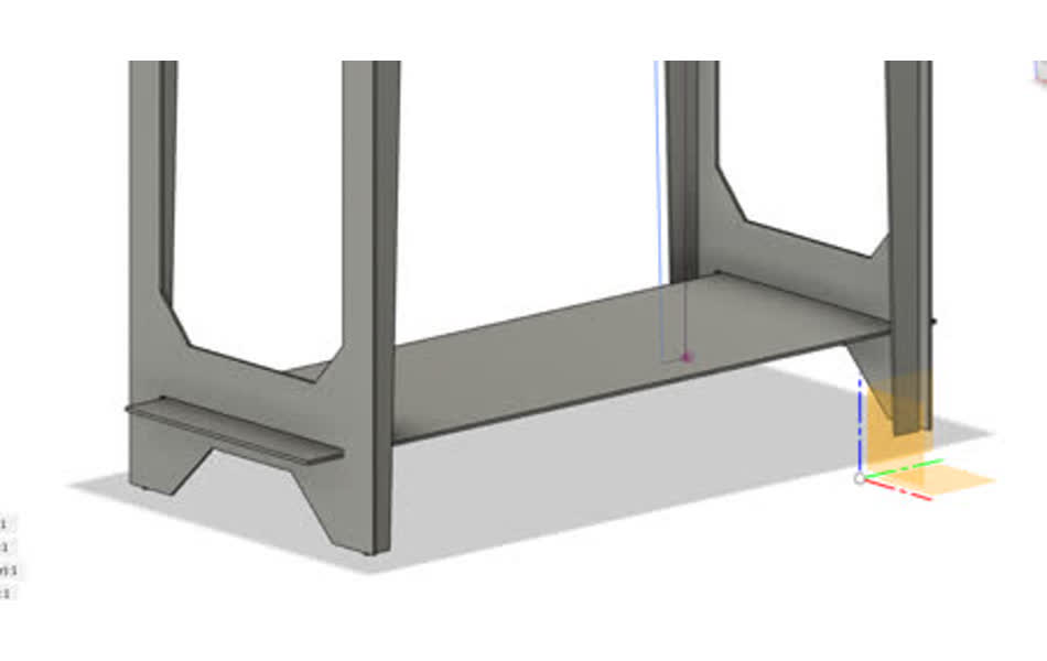
Also, instead of wasting the floating bottom shelf, it could be used to reinforce the width of the legs at the base of the rack.
I was getting too caught up in following whatever design rules had worked for others because I know nothing about furinture design - but THANK YOU BEN for reminding me that most of this is common sense physics and walking me through some simple structural design rules! Ben does all his CADing in Rhino {{potentially a dangerous move}} and he helped me rebuild my model mostly from scratch.
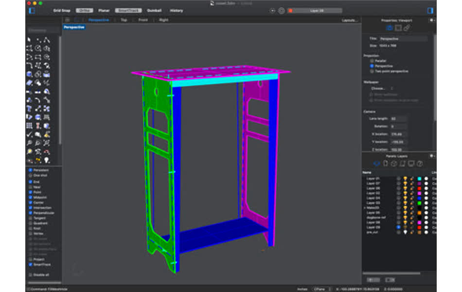
Off the bat, Rhino is more intuitive to work with than Fusion. It also has a command line interface, which I had really enjoyed when working with Eagle last week. There's also much better documentation for it - when trying to google to fix something in Fusion, most of the asnwers are only given in 5-10 minute youtube videos that use an older version of the woftware with a much diffferent layout, whereas Rhino has nice written documentation and forums. So far, I'm liking Rhino much more than Fusion.
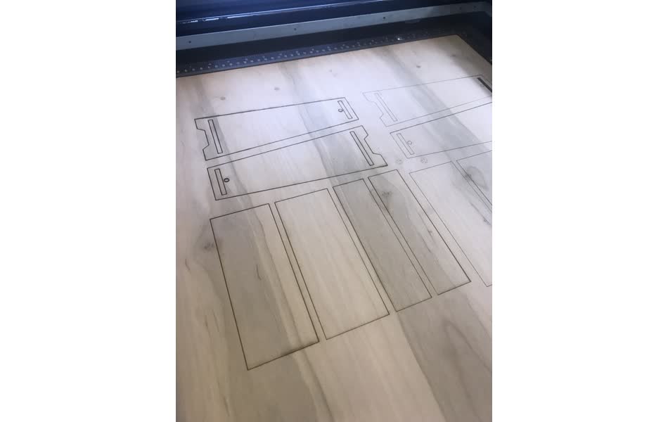
I turned all the surfaces into 2D cutouts with the simple `Make2D` command and it looks like I'm ready for another laser cut test run
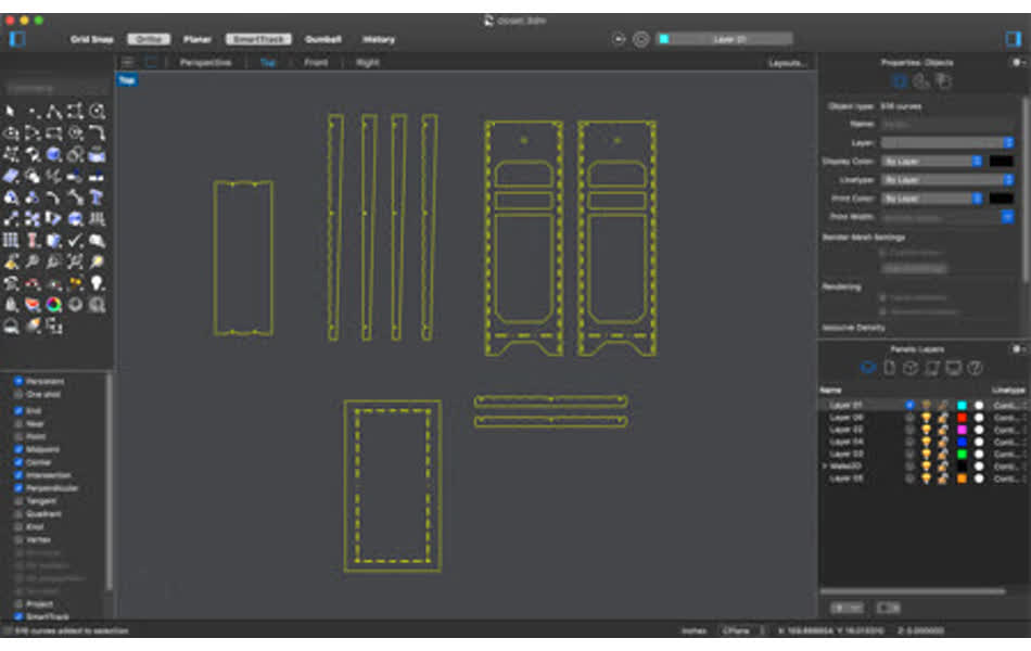
EXCEPT Rhino isn't parametric like Fusion, so I can't easily change the material thickness to match whatever cardboard or thin plywood I want to cut on. I tried to scale all of the cutouts to have the 0.5 inch design match the thickness of the cardboard, but the final clothing rack was still too large to laser cut. {{many points against Rhino, back on team Fusion}} I decided to go ahead and cut the small scale version, with the wrong slot sizes, just for a sanity check that they would all at least line up even if it doesn't fit. I was worried because I had modified the 2D designs quite a bit from the 3D model. Adding the nut and bolt fixtures in the 3D model was much more complicated than doing it in 2D, so I added them in 2D instead, but want to double check that they were aligned properly.
Everything seems to line up fine, so I'm finally ready to cut . . .
CNC Milling
path planning
I had some time reserved at the ShopBot, but everyone was running behind schedule because the toolpath planning in VCarve takes much longer than expected and the ShopBot software is finicky. Finally ready for my turn at the mill, I needed to dogbone all of the corner cutouts in my design and for some reason, most of my curves were left open with invisible overlapping edges and so the path planning was going painstakingly slow in VCarve. So I got off the machine to let some other more prepared people get a turn to cut.
It turns out that all the open curves and invisible line segment overlaps cam from the edits I had made in Rhino. I started to get the hang of the software as I cleaned up the curves:
- `Explode` will separate everything into it's most basic line segments and the bottom left corner will tell you how many peices it expanded to
- to close two line segments into one, you have to make sure you're clicking the point that's tagged as "End"
- `Join` will bring together everything that's selected into the minimum number of curves and the bottom left corner will specific how many curves were created and whether they are open or closed
- sometimes a curve looks closed, but it's actually open due to a tiny overlap or opening so `CrvStart` or `CrvEnd` can be used to find the open point
Dogbones complete, curves cleaned up , and I'm ready to head back to milling. I created the tool path in VCarve sucessfully, but when adding tabs to the cut VCarve gave me an error that the tabs won't work becuase the "toolpath is smaller than the tool". I couldn't find a reason for the error and Tom said he had never seen it before, so I just sent the path as is without tabs since my cut peices are large.
finally milling
BUT I shouldn't have ignored the error ....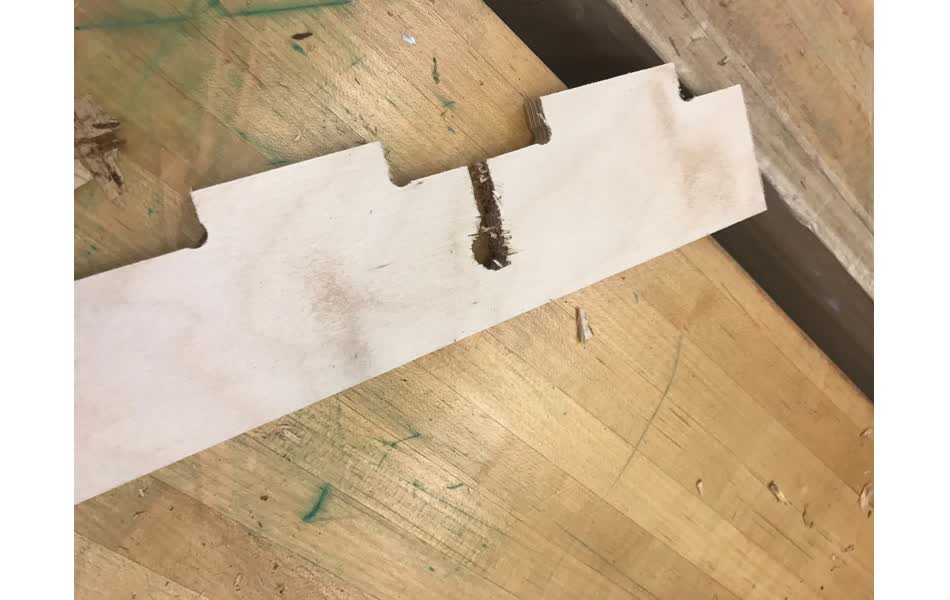
The design includes small t-shaped cutouts to hold the rack together with fasteners. If the whole piece is cut out first, then when the mill goes to cut the fastener hole, the peice will rattle and the cut isn't precise.
I quickly stopped the job and had to go back to path planning. Since Tom and I couldn't figure out where the error for the tabs is coming from, I decided to split the milling job into two different paths - one that would cut all the smaller innerholes first, then another that cuts out each of the pieces. Back to Rhino to turn the fastener cutouts into their own closed curve, then back to VCarve to reorder the tooling . . .
Cutting my first peices and everything seems to be finally working !!!
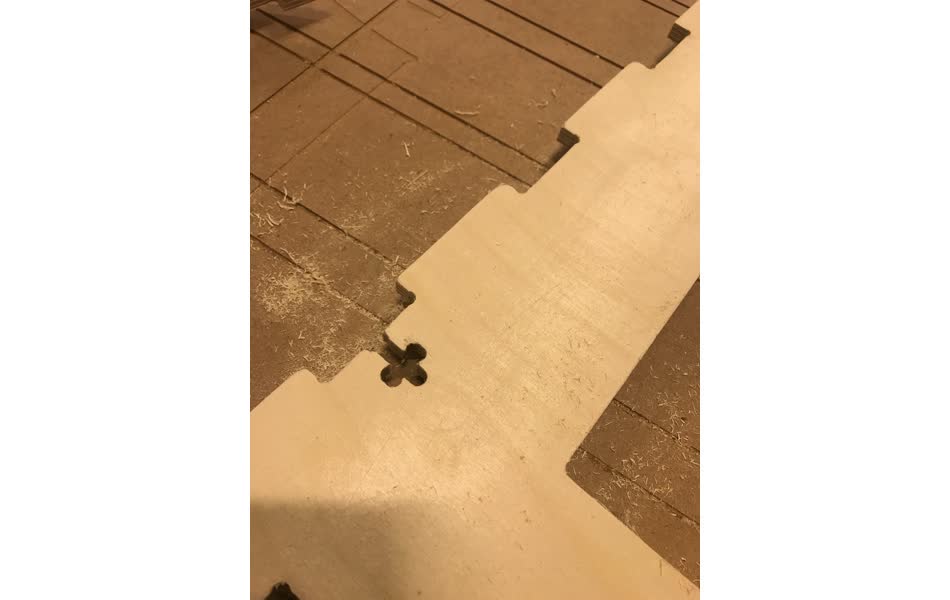
Except, in the midst of my Rhino editing, somewhere between cutting the cardboard prototype and milling the peices, I misaligned the finger joint sizes. The leg of the clothing rack doesn't fit into the side panel . . .
This is why you probably shouldn't be CADing in 2D only in Rhino - there's nothing to save you from stupid oversights like this. It being Wednesday morning before class at this point, I'm taking a day or two away from the clothing rack and will try to salvage the rest over the weekend.
Back to CAD
Since I have a limited amount of wood, I decided to save the side panel (the larger part) from the mismatched finger joints and redesign the clothing rack in Fusion around this fixed part. After a conversation with Jake on the pros/cons of Fusion vs Rhino, it became clear that they are two different tools designed to do different things and the best process may be to use both. So with a fresh-ish start my next steps are
- paramterize the design in Fusion. check that everything is right in the physics.
- export .dxf of each body to Rhino to do fillets, dog boning, or add any artistic design. double check that everything is right in the physics.
- plan the tool path in VCarve to send to the shopbot!
Fusion 360 tips
Zach seriously helped my regain some confidence in Fusion - he walked through the first few steps of my design with me and showed me how he would go about doing things and why. Some key tips and tricks that he showed me and some others that I found along the way:- do as little as possible in sketches so that you're able to separate actions into timeline features and can easily go back to change, as opposed to trying to do everything in 2D.
- to make parts line up together and then join them
- select both components > right click > align components. it will move them to the closest alignment position.
- To make this permanent - select both compoents > assemble drop down > as-built join
- to add repeatable joinery (like the finger joinery in this case):
- make a sketch of the most basic shape you want to repeat
- extrude it to bring the single pattern to the body
- rectangle pattern along whatever direction you want and the patern repetition can be specified by distance between each shape or the total number across some distance.
- distance dropdown in extrude or push pull tool can be set to a defined distance or to another object or through everything in its path
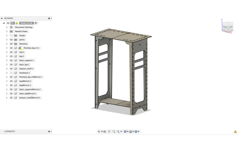
I changed a few design elements with this version - the bigest thing being the extra corner support at the top of the rack. I did this to help constrain the rack in the lateral direction - the best way to do this is to add two diagonal wires across the back - but I figured I would try experimenting with the sturdy corners to see if they would be supportive enough and I like the look of them anyhow.
Off to Rhino to see how to make this fit on the remaining wood
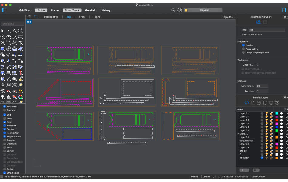
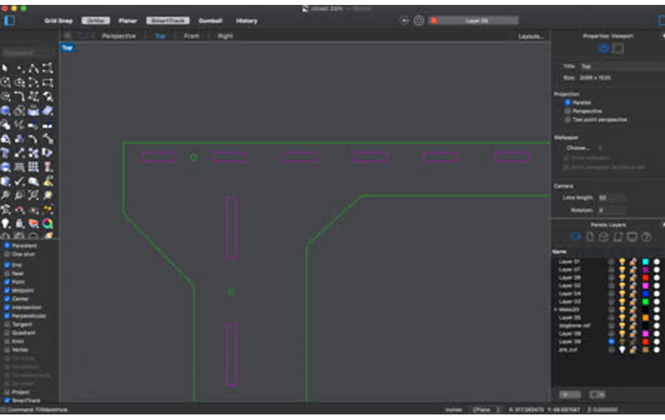
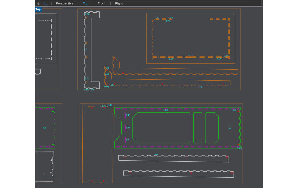
triple checking work
I have 3 pieces of 96" by 48" plywood and any brown lines indicate pieces that are already cut from the wood. The first column is the original design with the mismatched finger joints. The second column is the updated design at the original 48inch width. There was no way to have all the pieces fit on the wood, but luckily the Fusion design is parameterized! So I changed the rack to be 45 inches wide so that some pieces can fit along the 48 inch board. The third column is the updated design with 45inch width - this will be sent to the mill.Double checking the physics with some distance measurements in Rhino and everything looks good . . .
I split up the tool path between the small fastener holes and large cutouts like before and send the first sheet to the mill.
Back to Mill
Everything fits so far - woo!! I sent the second sheet to the mill. I did 3 passes on 0.5 inch thick plywood and each milling job took about 40 mintues.
sanding
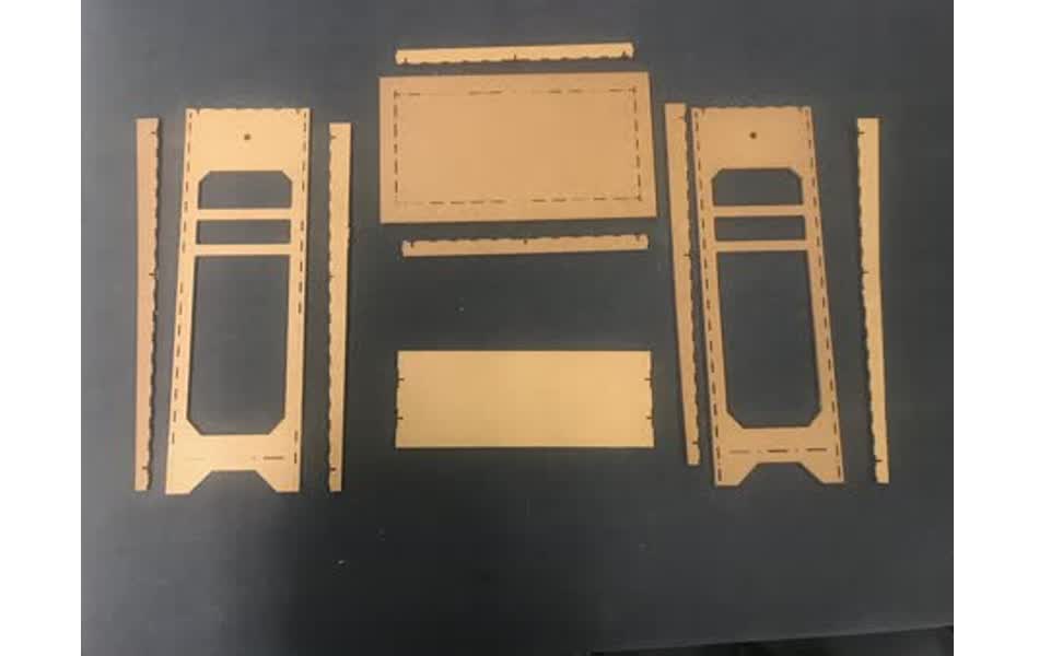
Everything milled and appeared to fit well - time for lots of sanding . . .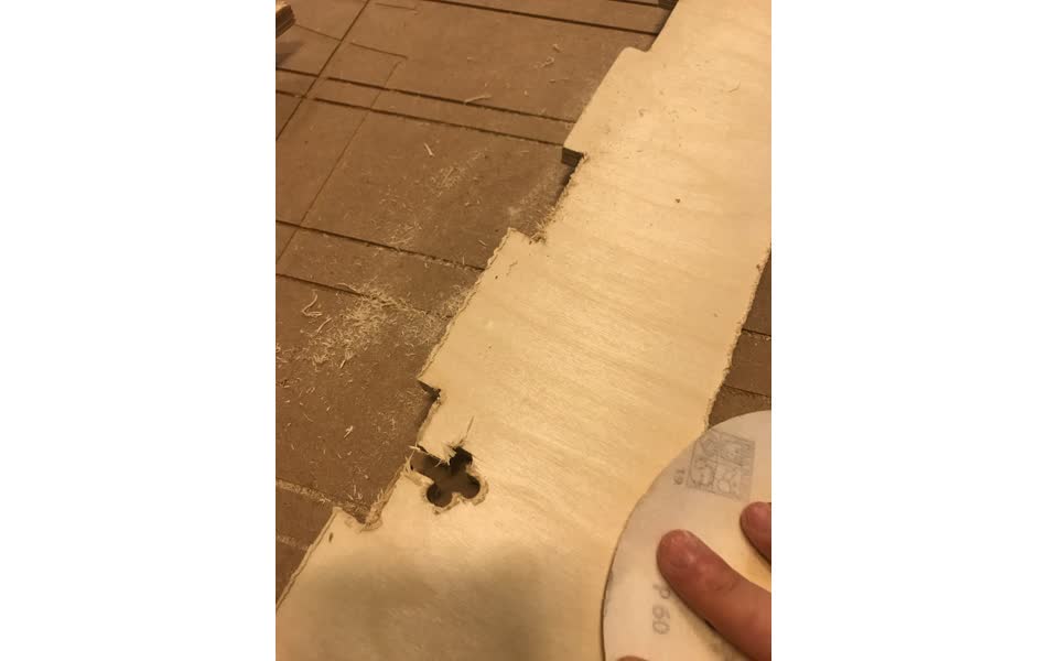
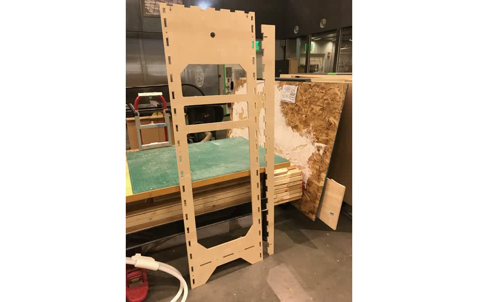
assembly
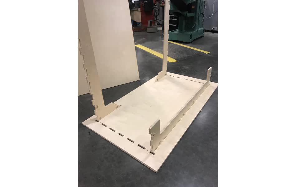
A couple of areas needed cleaning up - some of the fastener holes were not big enough and one of the finger joints near the bottom of the front leg needed to be cut smaller. But Ben helped me fix these manually, then we got the giant thing assembled!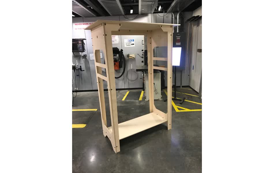
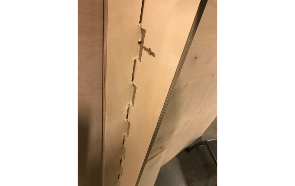
The fastener joints did't come out great because the cutout for the nut is slightly too large. I overshot this value because the first time I cut it they were too small and not properly dogboned. I did not think it would matteer if they were slightly larger, but when assembling Ben explained that ideally the nut fits snug enough so that it stays put while the bolt tightens. It is not a major mistake, but something to keep in mind if I use this joint again.
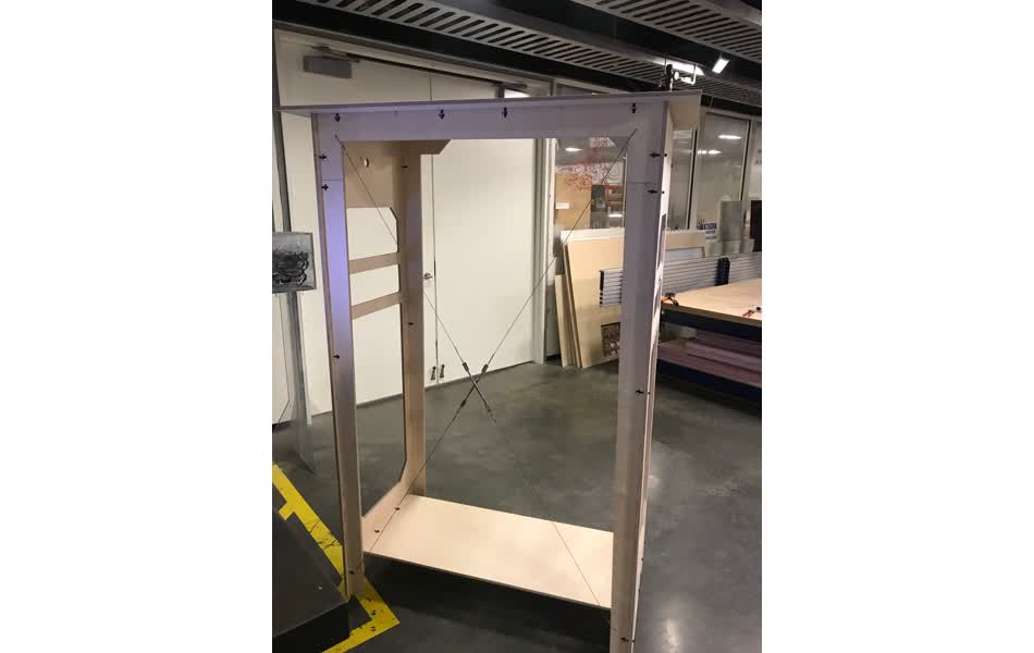
Also, the corners at the top of the rack are not strong enough to act as a shear wall. The structure appears to be wobling around the back support and back legs. So I added steel wire in an X accross the back to better support that degree of freedom.
Now I just need to get a dowel so it can actually have a rack and assemble it at home :).
I went to Home Depot to get a wooden dowel to hold the hangers, but they didn't have one long enough. So I got a 1.25" diameter copper pipe that should work!