Hoping to make something to prevent me from getting locked out.
A tracking page for my final project: the Key-Minder, a Re-Minder for your keys!
My final video!
Brainstorming for my final project
Weird doorknobs, and getting locked out.
The inspiration for my final project came at a really unfortunate time, where I locked
myself out of my dorm room at Wellesley.
Last year, my roommate and I had a door that would stay unlocked once the lock had been turned
(with the key); however, our door this year stays locked from the outside even once
somebody has entered the room with the key. Wellesley charges $10 or $15 per lockout after
a certain number of offenses, and I really don't want to get fined for being
locked out too many times, so I need a way to remember to keep my keys on me at all times.
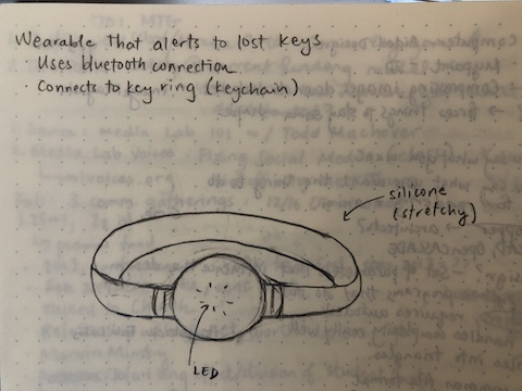
After some thinking, I decided on a wearable, similar in size and shape to a wristwatch,
that would alert me if I strayed a certain radius away from my keys.
I'm currently thinking that it will be housed in silicone, and will connect to a keychain via bluetooth. The
wearable will have a small light, which will light up if the bluetooth connection
is lost because of increased distance between the wearable and the keychain.
Attempt #1 at making the body of my final project
Using week 8 (molding and casting) to try and make some progress
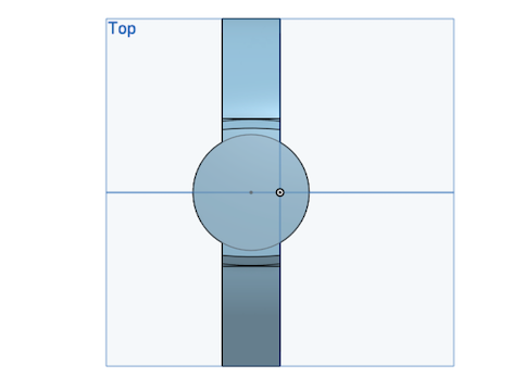
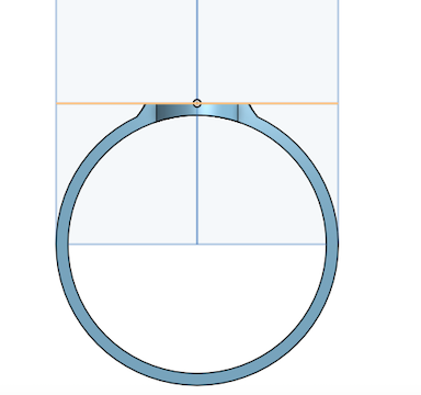
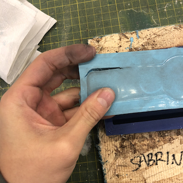
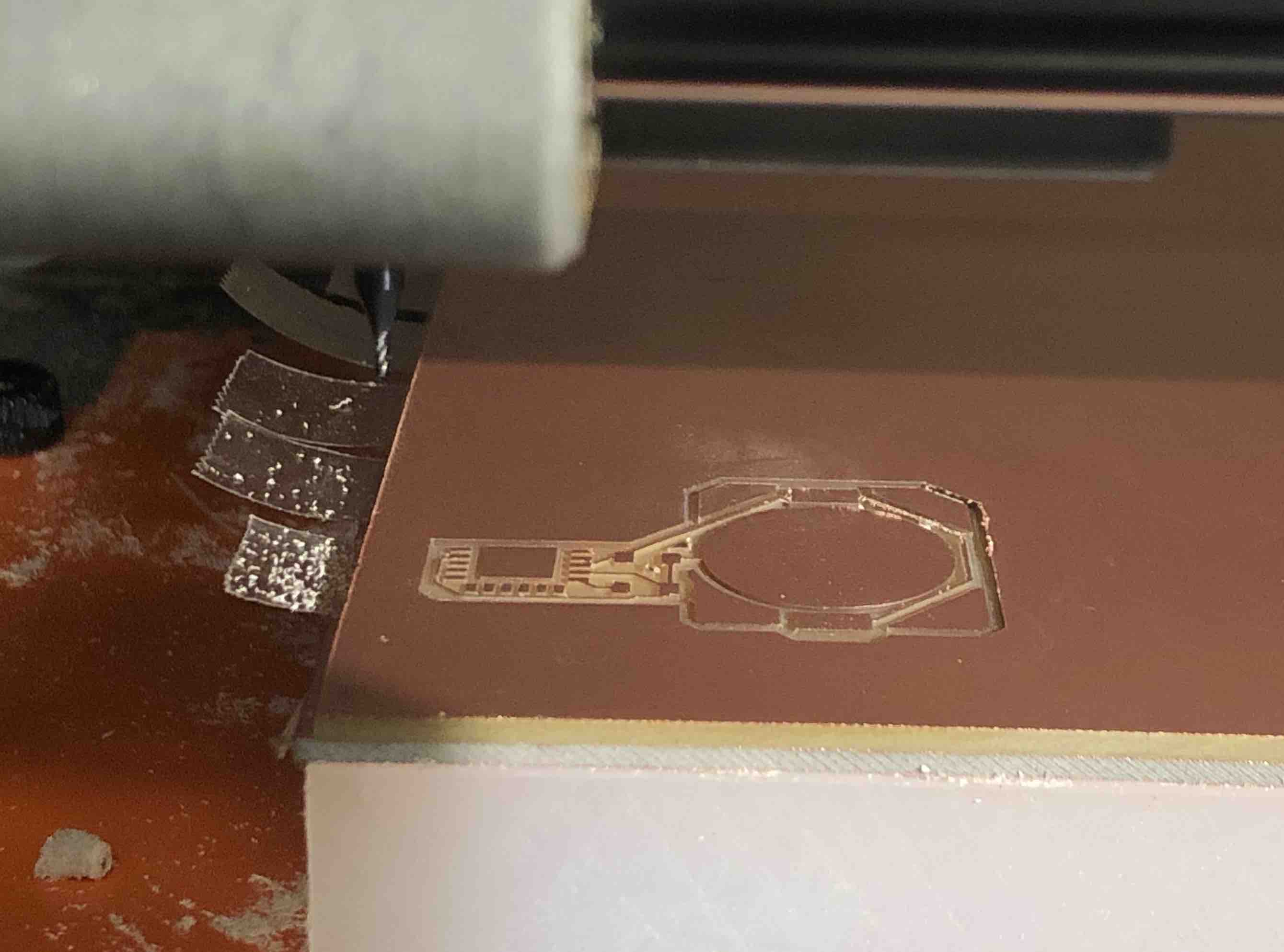
During week 8, molding and casting week, I decided to try to make the body of the wearable, which
I imagined would be a silicone-type material. First, I re-cadded so that my wearable was flat instead of
circular, then milled it into a wax block. Unfortunately, pouring Oomoo into Oomoo didn't go as planned;
it seemed like the whole thing just glued itself together, mold and all.
Some ideas of where to go from here:
Re-try the Oomoo/Oomoo cast, this time, leaving the mold overnight to cure without a doubt.
Re-make the mold with Moldmax and cast into it with Oomoo.
Try a different method of casting altogether (I heard some talk of using laser-cut cardboard to make shapes in Oomoo?)
Try a different method of making the body, like maybe using a composite or something like Jack's 3d printed fabric.
More brainstorming for the final project
Meeting with Jiri, 11/4/19
Instead of recitation this week, we've all scheduled 1-on-1 meetings with TAs to chat about our final projects. My
meeting with Jiri was super helpful, and I'm very glad for his calm and saintly levels of patience as I asked many
panicked questions about electronics.
Takeaways / notes:
Haptic feedback instead of LED: a small rotating motor
might be more effective to alert the wearer about a set of missing keys.
nrf24l01
instead of bluetooth would work better in a noisier environment, such as the final project demo.
In general, decreased wave speeds tend to work better in noisier environments
A strategy to try: have a module send something, if it doesn't get return a signal within 30 secs, consider it "lost".
If there's an acknowledgement from the receiver, consider it "successful".
Keep this in a loop so that if the connection is unsuccessful, it will automatically re-try.
Consider using RFID, which would mean no need for an active element on the keychain.
It's a coil that works like an antenna and powers a small circuit. Apparently, the Signal
Kinetics group uses this a lot and would be good to talk to.
Thinking ahead to ordering parts for the project: make a component list, including stuff like
processor, radio, motor, battery...
Pogopins
could be a good way to make the bulky ISP header (which has been an integral part of all of the boards we've made so far)
smaller.
Continuing on the topic of size: my original CAD model might not leave enough room for fitting the electronics inside.
Final week, day 1 (Thurs)
Getting started
-3d printed the band on the objet.
-got button cells and clips from anthony and zach.
-made an initial keychain module using the RN4871.
-got the keychain to work.
Final week, day 2 (Fri)
Switching
Today, I struggled with C for most of day, and then went to EDS to get some help.
After talking to Alexandre, I decided to switch to radio communication using two
NRF24 modules, as this would be easier to program. Alexandre did warn me that packaging
would be harder with the NRF24 modules, since they're bigger, but I am so much less
confident about my coding ability than my "get things to fit together" ability, so I figured
it was a worthwhile switch.
I realized that for the transmitter chip I could just attach a battery to one of Neil's
hello-world boards and call it a day, and that for the receiver, I would add an LED and a
battery. This was a lot less fussy than I'd feared. For a starting point, I decided to
make both boards but not bother with the battery and power them over an FTDI, and figure out
the battery part later. Here are the files:
TracesOutline
Re-designing and re-routing took much longer than I expected, so that was the rest of my day,
unfortunately, but I'm optimistic that the rest will go more smoothly because of this change.
Final week, day 3 (Sat)
C
The main perk of the new module that I've switched to is that there is a lot of documentation
on how to use it, namely, Rob Hart's
project. Alexandre helped me with some modifications to the C code on Rob's page, which
was really wonderful as I still struggle to read existing C code and figure out what each line
is doing. I did some more modifications, and then ran into some bugs, which Zach and Eyal helped
me figure out. Thanks everyone!
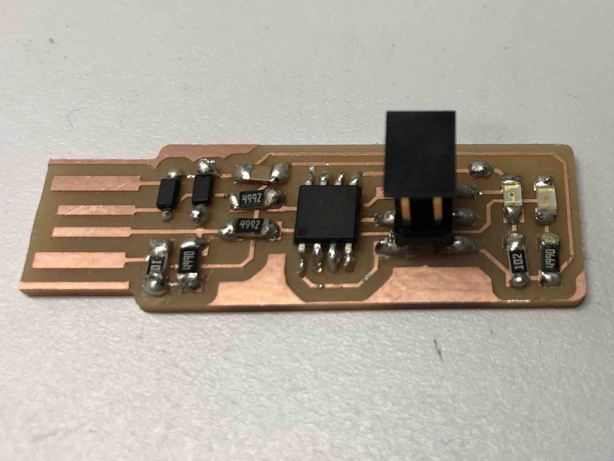
I also made a transmitter board, which involved more milling and soldering:
Speaking of which, I'm so proud at my progress at soldering- here are some
photos of the board I made in week 3 compared to the ones I made this week.
These two are photos of some of my first-ever boards:
Here's a closeup of some of my soldering this week:
So, actually, the second-to-bottom board was made later in the week. But the bottommost board
was a receiver board that I made today!
First, though, I made the transmitter board: for this, I decided to use Neil's
example hello-world board. I decided to do this for now (and make my own version with a battery
and LED later) because I just wanted to test the radio communication and have serial data via
the FTDI header, which I plan to leave off for my final boards to reduce size. Here's a photo
of the transmitter:
The transmitter, as expected, was straightfoward to program, but I kept getting the "rc=-1"
error when I tried to program my receiver board. I decided to call it a night and figure
out why tomorrow.
Final week, day 4 (Sun)
Board problems
A new day with fresh eyes really explained everything.
I took a closer look and realized that some of my traces had fused together:
I decided to exacto knife the traces apart, to save time re-milling a new board, but accidentally
ripped one of the traces. In desperation, I tried to solder the trace back together, and when that
failed, I soldered a wire in between them.
However, this board immediately heated up when I plugged
it in (I burned my fingers a little bit), so it's safe to say that my strategies to salvage it didn't
work out. I realized I'd set the isolate value in Eagle to 0, so I set that to a higher number
and milled another board, which, unfortunately, had the same issue. While looking at this new board,
I realized there were actually three spots that had fused together, not just the one that I'd
seen in my previous board. That would explain why it didn't work even after I "fixed" it.
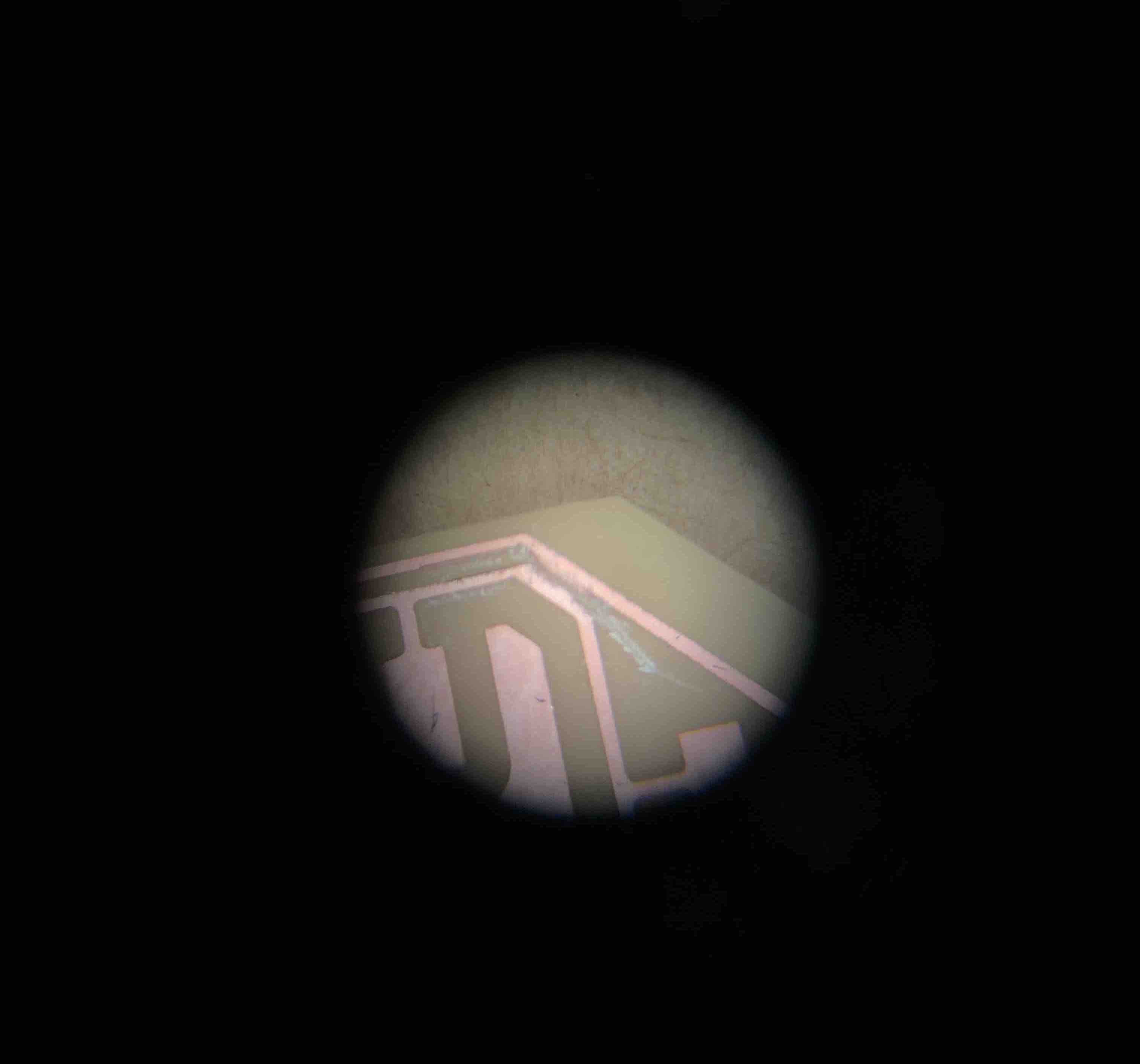
I went for a scalpel this time, and cut the traces apart without ripping anything. First,
I checked using the magnifier in the lab:
I proceeded to stuff this board with its parts.
This time, everything worked!
At this stage, everything is plugged into and powered by the computer. However, what should
be happening is that the LED on the receiver turns on after a certain amount of time of not
getting any signals from the transmitter, and then the same LED should turn off after receipt
of a message. In the video, I let the receiver sit for a few seconds, wait for the LED to turn
on, and then plug in the transmitter. This causes the LED on the receiver to turn off. Success!
I also checked this from the transmitter end by plugging the transmitter into the FTDI cable
and running miniterm.py. This showed the transmitter's status and let me check to see if
the transmitter thought that messages were indeed being delivered:
Excited by this, I decided to go ahead to design boards that would run off battery power
(because nobody wants a wearable tethered to a computer). Routing was another fun challenge and
took a bit of time, but the milling, soldering, and programming all went smoothly!
I got paranoid from the previous milling experience, so I also used a multimeter
and checked the board for shorts before stuffing it:
I also added
an LED to the transmitter board, which actually made both of the boards the exact same, physically,
which was very convenient. To differentiate, I put a blue LED on the transmitter and an orange
one on the receiver (we ran out of red LEDs).
Wowza. This was very exciting!
Unfortunately, it stopped working after I went and ate dinner, came back, and tried to package it
into a smaller shape. Could not figure out why, so I decided to call it a night.
Final week, day 6 (Mon)
The next day, I came up with a list of potential reasons why my project stopped working:
Orientation of the radios: the chip probably gets cranky if I put it too close to
the rest of the board.
A code issue? I'm not sure why this would be the case, since I didn't change the code
at all before and after eating dinner.
A short in the board: this seems likely, since the error comes and goes. If not a short,
then some other hardware issue.
My battery could be dying: if the microcontroller doesn't get enough power, it could
misbehave.
Here's what I did first:
I first tried swapping the batteries out, since this seemed the easiest fix, but that didn't help.
Re-loaded the code onto all of my boards.
Checked the boards for shorts (didn't find any), and then used the soldering iron
to re-flow all of my solder joints for good measure. I realized that a regulator had literally fallen
off of one of my boards, which could have been part of the problem.
Unfortunately, this didn't really help, so I decided to use my transmitter that had an FTDI connection
(I'll call it the "FTDI transmitter" for the purpose of being succinct, even though this isn't at all correct)
as a debugging tool, since it (helpfully) talks to miniterm.py to tell if a message is being delivered and
if the delivery is successful. Through this, I also realized that the radios wouldn't work if I plugged the
battery in first, then the radio module - the whole thing (microcontroller and radio) had to be powered initially at
the same time. I also unpackaged the transmitter and receiver modules, giving the radio some space from the chip.
Finally, things started to work again! I then squeezed the modules together into a smaller shape
for packaging, testing things periodically to see if I'd made the radio cranky again by putting
it in a bad orientation. I found a shape that seemed to work for the chips, and stuck with it.
While I was struggling with this, I also CADded and started a 3D print of a case on one of the
Prusa printers. This one had translucent filament, so it would be perfect to let the LED shine
through!
The case came out looking pretty good, and importantly, the parts fit into each other.
The fit was a little too tight, though, so I sanded the sides down to get them more to the
ideal size.
I also tested the range of the radio by running around with the receiver module to see when
the orange light would turn on. Eyal also helped me a bit with this- thanks Eyal!
I did a few more things:
My code for the receiver turns on an LED if it counts above a certain number of times a loop has been
repeated. This loop is checking for a transmission. So, if it checks above i (a variable) number
of times, it assumes the connection is lost and turns on an LED. To make the LED turn
on sooner (to reduce delay), I decreased the threshold number.
I printed a backup case in *case* (pun intended) something breaks.
Unfortunately, things stopped working again at around 10 pm. At this point, I'm a little frustrated.
Fortunately, Manvitha, another student in Molecular Machines, stopped by and helped debug my code!
Turns out, it was a code issue after all - we tried a bunch of things, some of which helped temporarily, but
after thirty minutes, things stopped working again. Then, Manvitha thought to remove the part
of the code that read the CS register, because we didn't care about the contents of any
communication between the boards, just that the boards were in contact. The way I think this works is
that the receiving chip has a buffer space in which it initially receives a message from
the transmitter. This buffer is cleared as bits are read, but there's a slight delay that comes from
receiving new bits, reading them, and then clearing them from the buffer. What might have been
happening was that the tramsitter was sending messages very quickly, which kept the buffer
completely full. This would cause the receiver to think it was still receiving messages for a while
even after the transmitter had been turned off, because it would spend a while reading the
backed-up messages in still had in the buffer. This could also explain the inconsistency of the
errors - the modules would work as expected when the buffer was not full, but would act up when
the buffer reached capacity.
This seemed to be the bug that was causing all of my issues. Thank goodness for Manvitha,
because I definitely would not have been able to do that on my own!!!
The finished product:
My code:
TransmitterReceiver

 Some ideas of where to go from here:
 Here's a closeup of some of my soldering this week:

 So, actually, the second-to-bottom board was made later in the week. But the bottommost board
was a receiver board that I made today!
First, though, I made the transmitter board: for this, I decided to use Neil's
example hello-world board. I decided to do this for now (and make my own version with a battery
and LED later) because I just wanted to test the radio communication and have serial data via
the FTDI header, which I plan to leave off for my final boards to reduce size. Here's a photo
of the transmitter:
So, actually, the second-to-bottom board was made later in the week. But the bottommost board
was a receiver board that I made today!
First, though, I made the transmitter board: for this, I decided to use Neil's
example hello-world board. I decided to do this for now (and make my own version with a battery
and LED later) because I just wanted to test the radio communication and have serial data via
the FTDI header, which I plan to leave off for my final boards to reduce size. Here's a photo
of the transmitter:
 I decided to exacto knife the traces apart, to save time re-milling a new board, but accidentally
ripped one of the traces. In desperation, I tried to solder the trace back together, and when that
failed, I soldered a wire in between them.
I decided to exacto knife the traces apart, to save time re-milling a new board, but accidentally
ripped one of the traces. In desperation, I tried to solder the trace back together, and when that
failed, I soldered a wire in between them.
 I proceeded to stuff this board with its parts.

 My code: