Drink Mixing Machine (EECS Machine Week 2019)
Project Summary and Inspiration
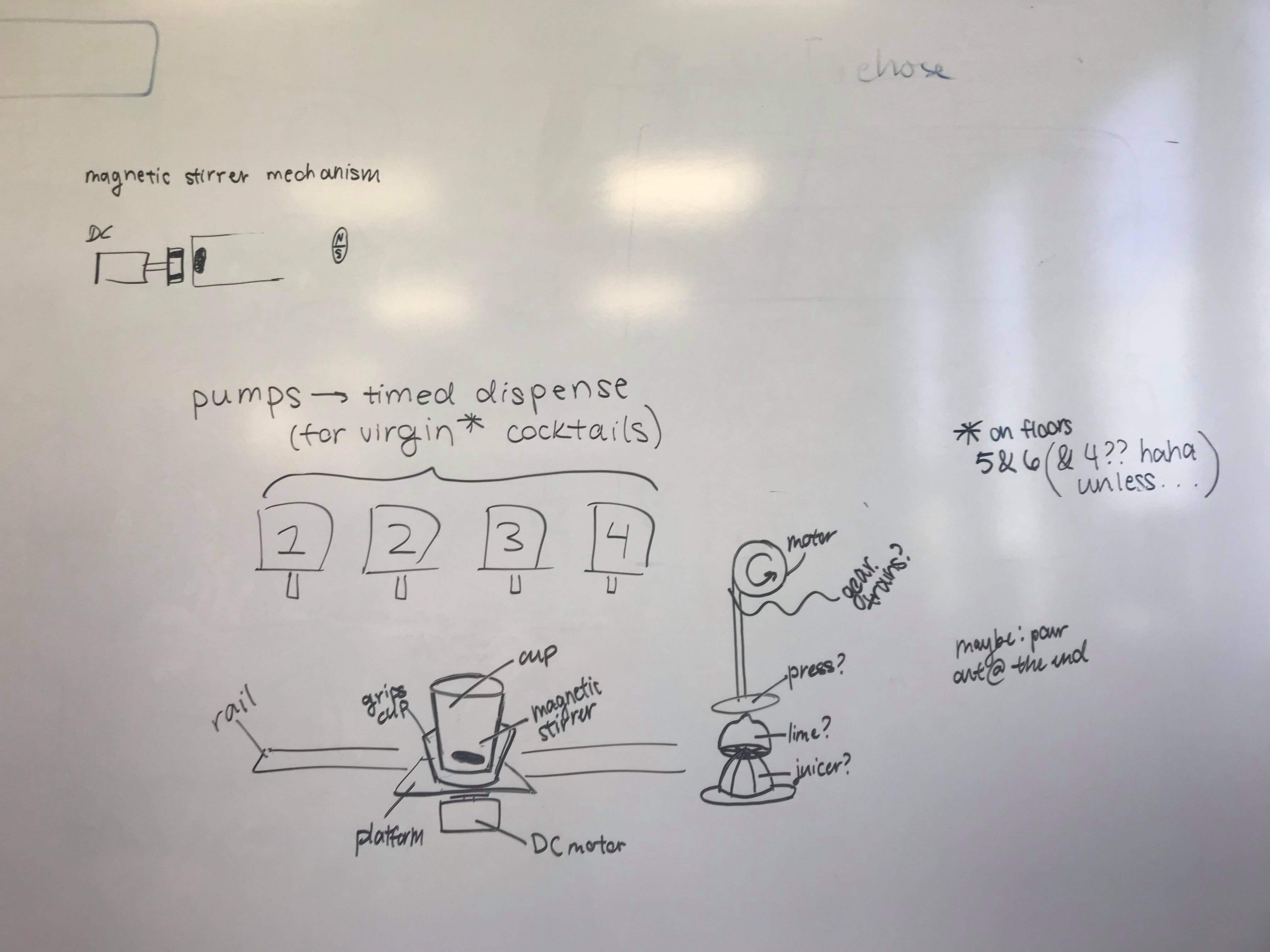
For Machine Week the EECS section thought it would be a lot of fun to make a drink mixing machine that would pump liquids from four sources into a cup and mix it. Last year's arch section had already attempted this. However, their implementation did not contain the usage of pumps (it utilized valves) that we thought using pumps, along with a completely new design, to implement this would make the project sufficiently different. Another place we pulled inspiration from was a similar arduino project we looked at here.
Starting Design
The starting design for this project was pulled from Jake Read's platonic gantry repo, using the RCTN23-0375HDPE Fusion CAD File. We knew that we wanted to get the machine chassis done first to get a better idea of how everything would fit together in the end. The general shape and function of the machine was clear: it would need 4 motor mounts for the pumps and a box-ier, more linear shape (since we had previously decided to focus on linear movement. Outside of that, we weren't exactly sure on the measurements of any of the pieces, since we were not completely sure on what components would need to ultimately end up on the machine. These uncertainties were things that the chassis CAD needed to account/leave room for.
After considering the drink mix machine more in depth we realized we needed to add the following design considerations:
- Designing around liquid
- Design that avoids leaks
- Design that allows for easy removal/insertion of liquids and cleaning
- Mixing the drink
- Stirred/shaken/other
- Stirred magnetically or not
- Pumping the liquids for the drink
- Go down an assembly line linearly or rotational
- Effect of pump size/length on flow rate
- Creating our own containers or using the original containers of the liquid
- Position of the cups
- Need to restrict movement in the x-y direction
- Gantry length
- Need to design gantry such that bottles can fit in an evenly spaced manner
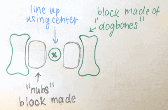
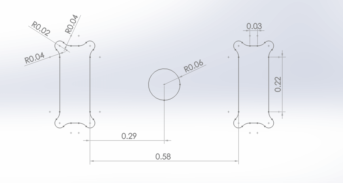
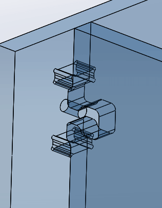
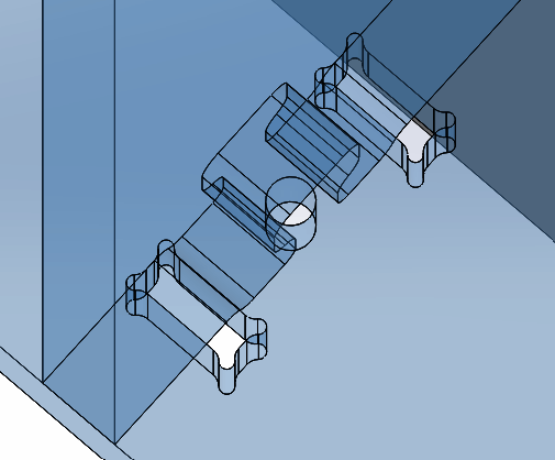
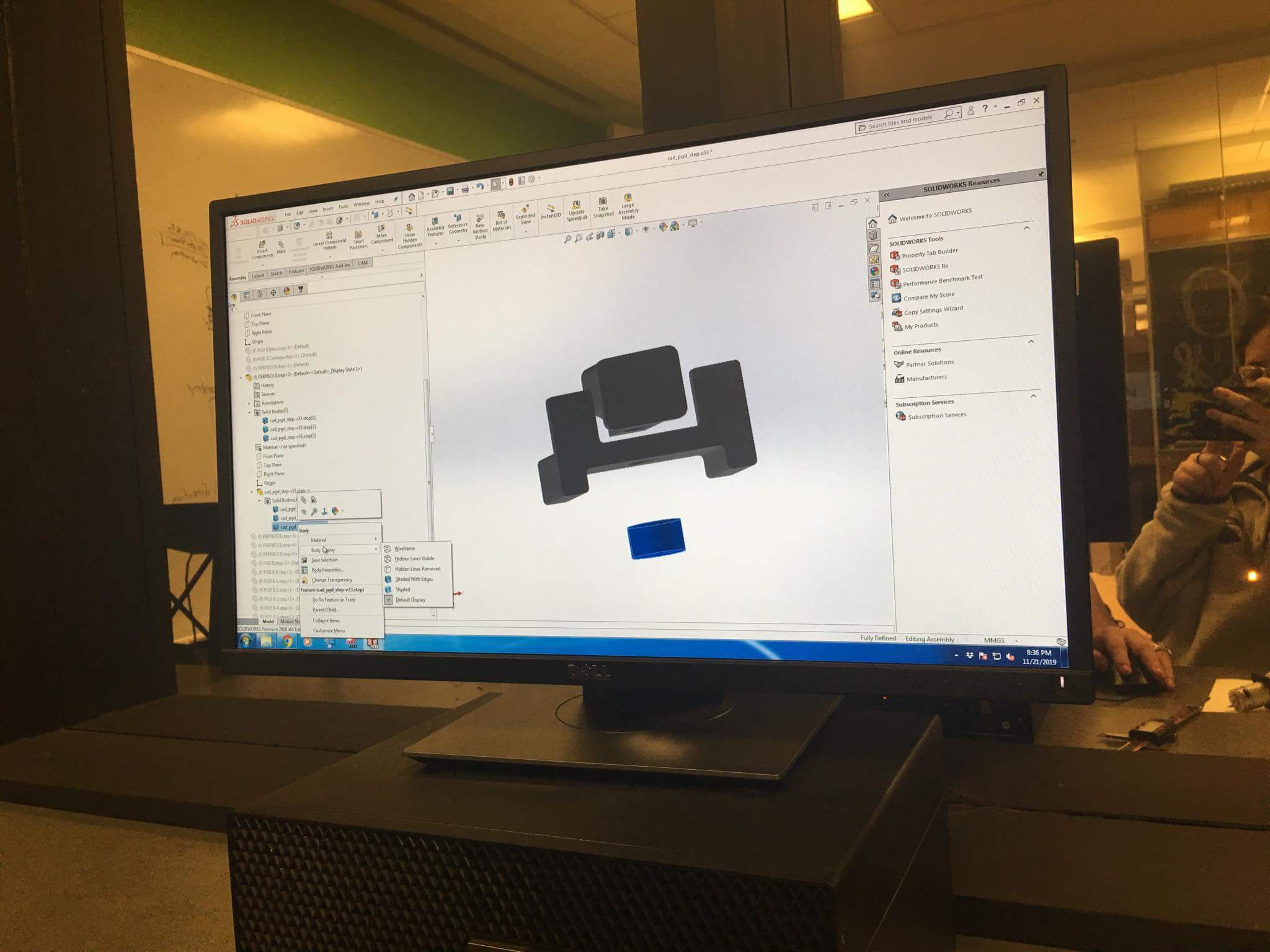
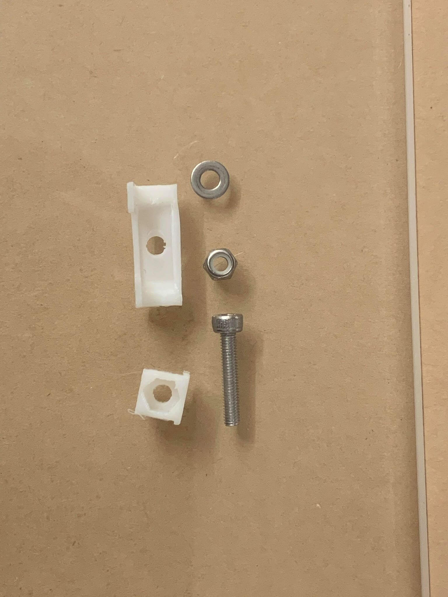
Jake's design uses joinery between acrylic pieces that are mediated with small 3D printed inserts. This allows us to avoid stress concentrations that would normally cause acrylic to crack. Noticing this, we decided to use this kind of joinery throughout our machine chassis. This presented a couple pain points, though. We pulled the .step file of the gantry into Solidworks to understand how exactly the joinery worked. Essentially, there are these dog bone shaped holes with a hole in the center. On the other side, there are two nubs and a valley (of some sorts) in the center. The nubs nestle between the side of the dog bones that are closer to the center hole and the center hole itself. A screw fits through this center hole of the primer and into the valley of the latter. The 3D printed pieces fill in the gaps in between.
We decided on magnetically stirring the drink and a linear movement of the cup below the containers. Considering these design restrictions and the ones outlined above we proceeded to design the CAD for the relevant parts.
CAD Designs
It's a bit of a convoluted process trying to get the joinery into a Solidworks sketch. First, isolate each of the pieces you need sketches from. Then, select the contours of the joints that you want to trace using "convert entities" and save them as blocks. These blocks would later be used in all of the pieces of the chassis for joinery. In general, some design constraints/assumptions we followed/made throughout the CAD process include:
- Total of 5 12'' x 24'' sheets of 6mm acrylic to use
- Jake's stress-reducing joinery will be used on the majority of the pieces so the acrylic doesn't crack so easily, otherwise superglue
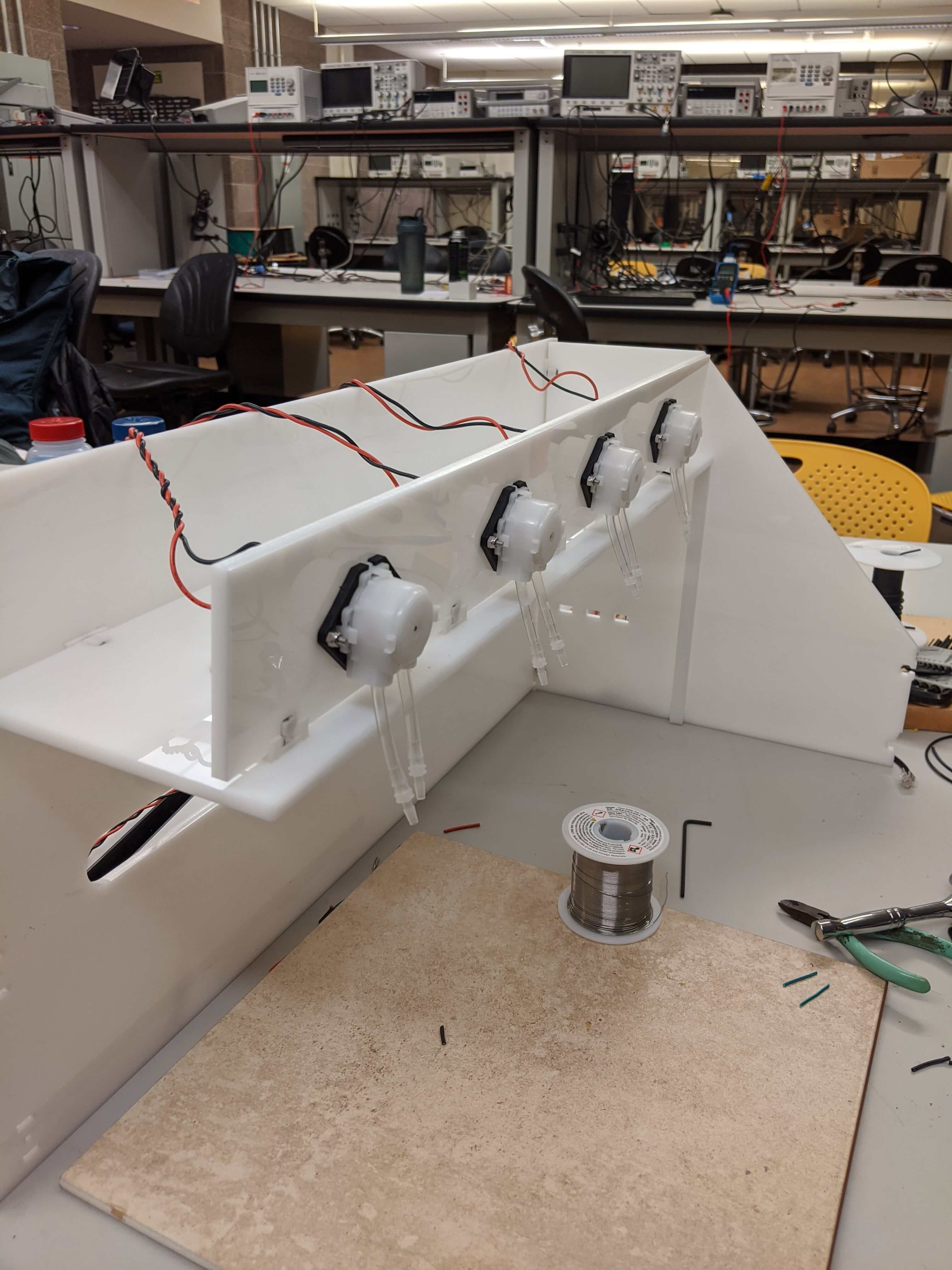
- The pumps will be mounted near or on the edge of the overhang, with one of the tubes pointing directly downward
- Pre-accounting for whatever wiring needs to happen later
- The gantry will need some mode of connection to the rest of the chassis
- The gantry needs to be sufficiently raised off of the flat surface the machine is sitting to ensure proper sliding motion

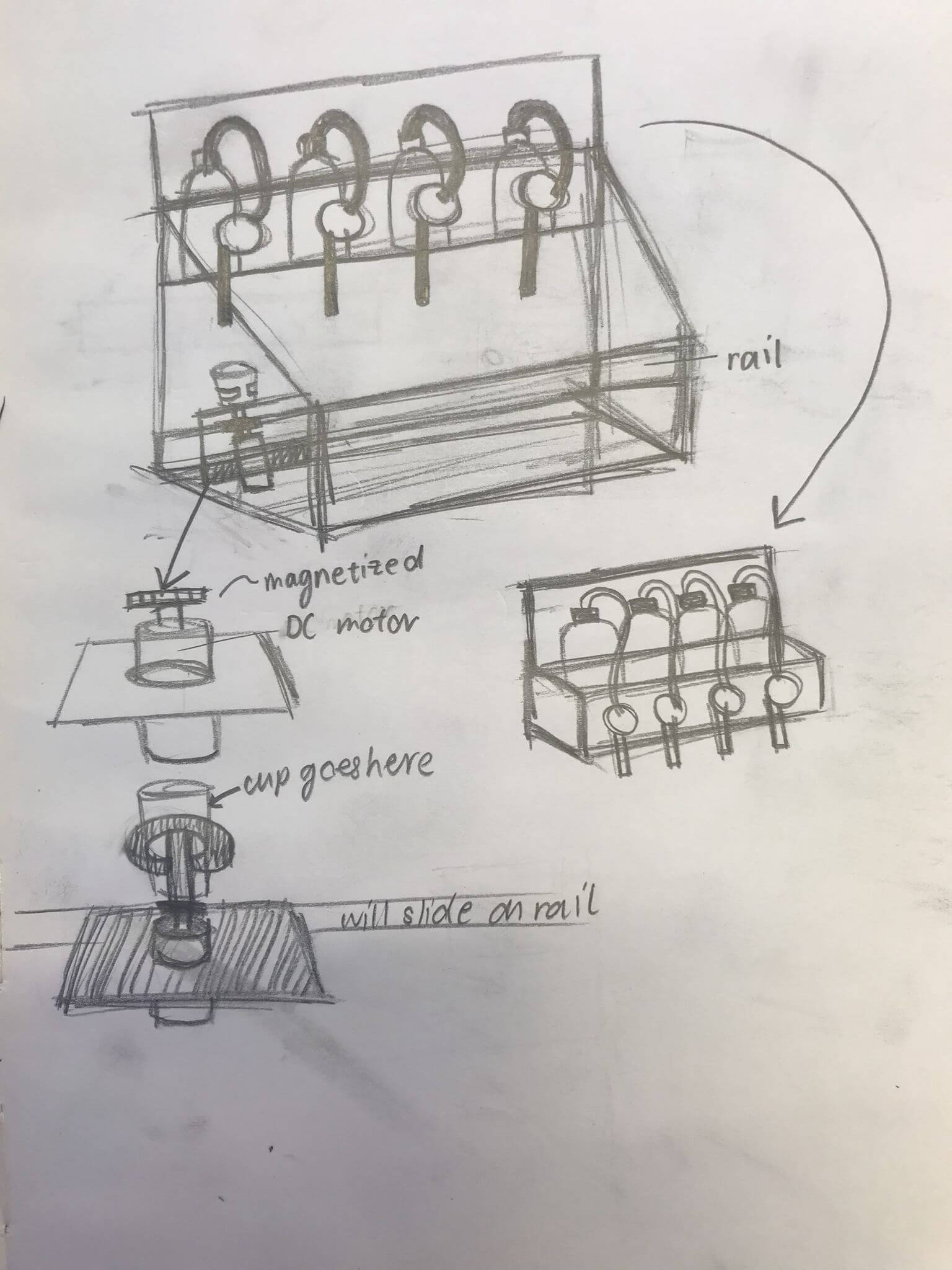
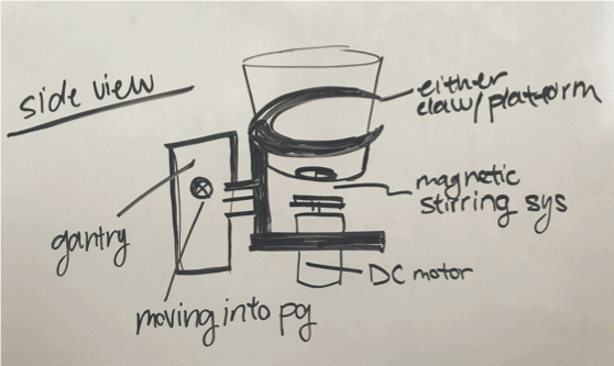
Cup and Motor Holder
In order to hold the cup, we had to add a design that would fit in with what Jake had, the CAD design for the cup holder and the motor below that would move it is below.The size of the cup will be about the size of a standard 12oz Solo cup with an upper diameter of 3.5''. The cup will need to rest on the gantry such that it's under the pump tubes.
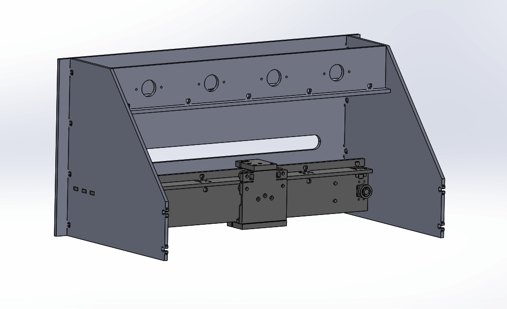
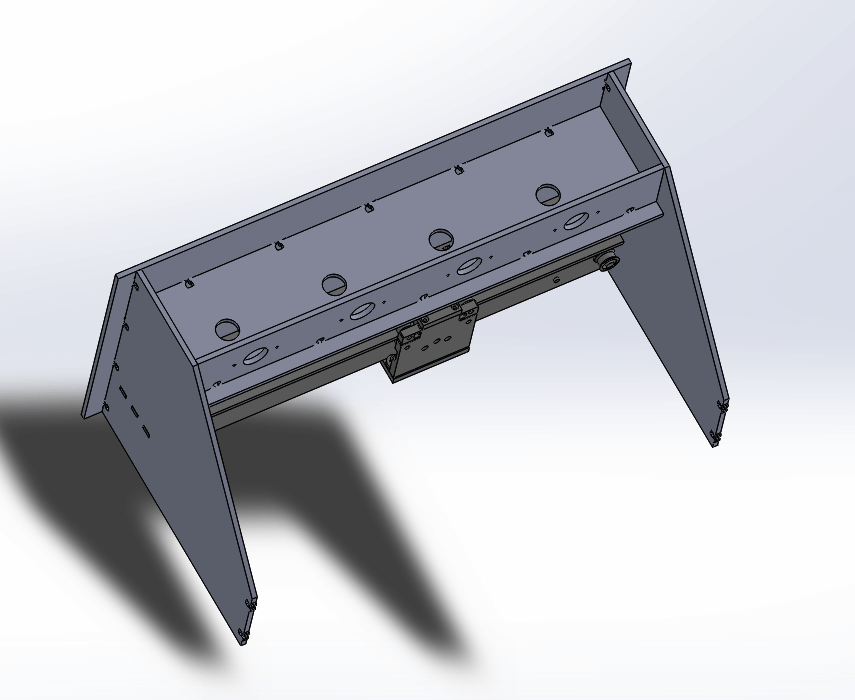
Machine Frame/Chassis
The chassis was designed from scratch and the relevant files are listed below and can be found in the Relevant Files section
- Back panel x 1 (drinkmachine_back.SLDPRT)
- Side panel x 2 (drinkmachine_side.SLDPRT)
- Motor mount panel (for pumps) x 1 (drinkmachine_pumpmount.SLDPRT)
- Bottom of motor mount panel x 1 (drinkmachine_pumpbase.SLDPRT)
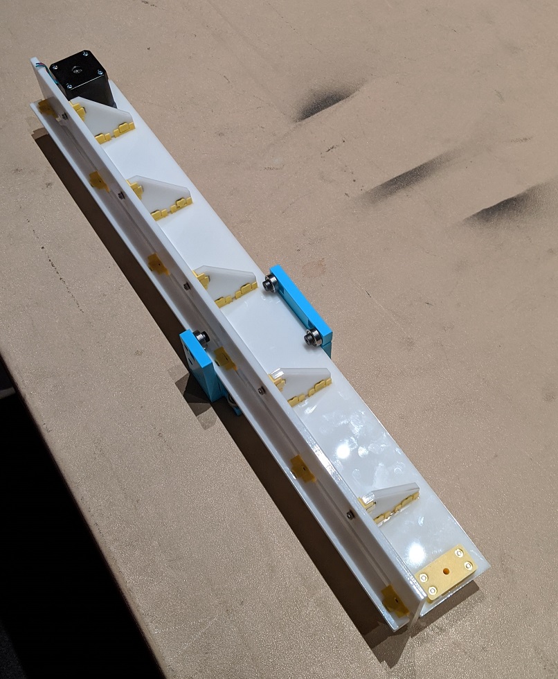
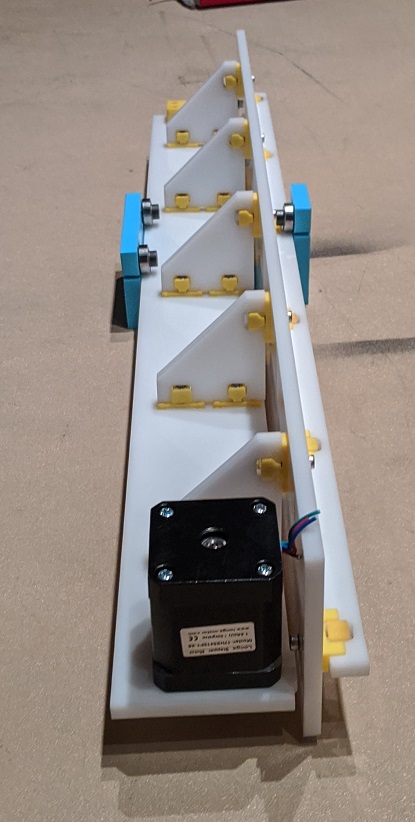
Gantry/Linear Movement
Here's a good image from Jake's documentation explaining the different components of the gantry:

- Horizontal panel (with length and teeth modification) x 1 (file.FUSIONPART)
- Structural triangles x 5
- Vertical panel (the part that has the pulley system attached) x 1
- Thinner vertical piece x 1
In the folder with all of the parts, you'll see drinkmachine.SLDASM. This is a Solidworks assembly made of the chassis .SLDPRT files and a .STEP file of the gantry. You'll also see that the back panel and bottom of motor mount panel have holes cut out of them. We prioritized the chassis CAD, we weren't yet sure of what wiring would happen and decided to add holes proactively. The holes were proactively made in case wires needed to pass through the back panels (for the gantry) or the bottom of the motor mount panel (for the pumps). Additionally, you'll see that the side panel, there are three rectangular holes. The corresponding teeth were added onto the edges of the flat panel. These teeth fit into the side panels and would later be secured with super glue. The only other thing we changed about the gantry CAD was its length so that it would fit within the side panels of the chassis.
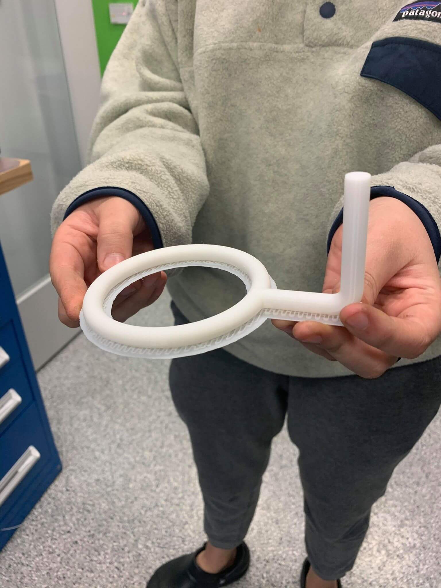
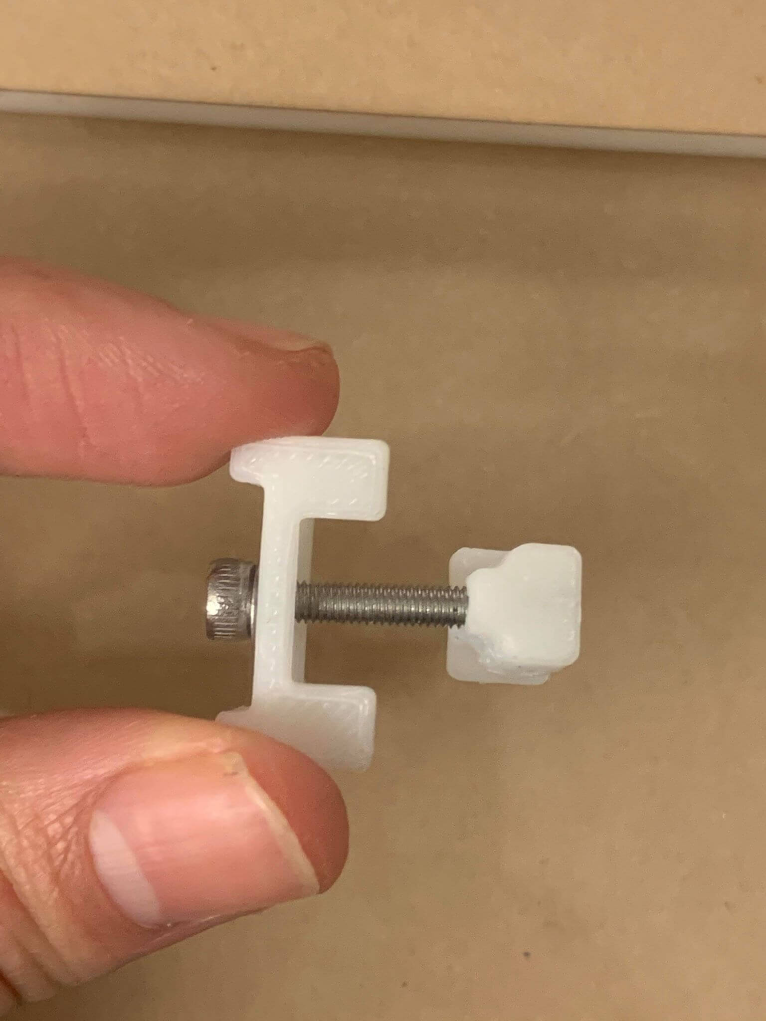
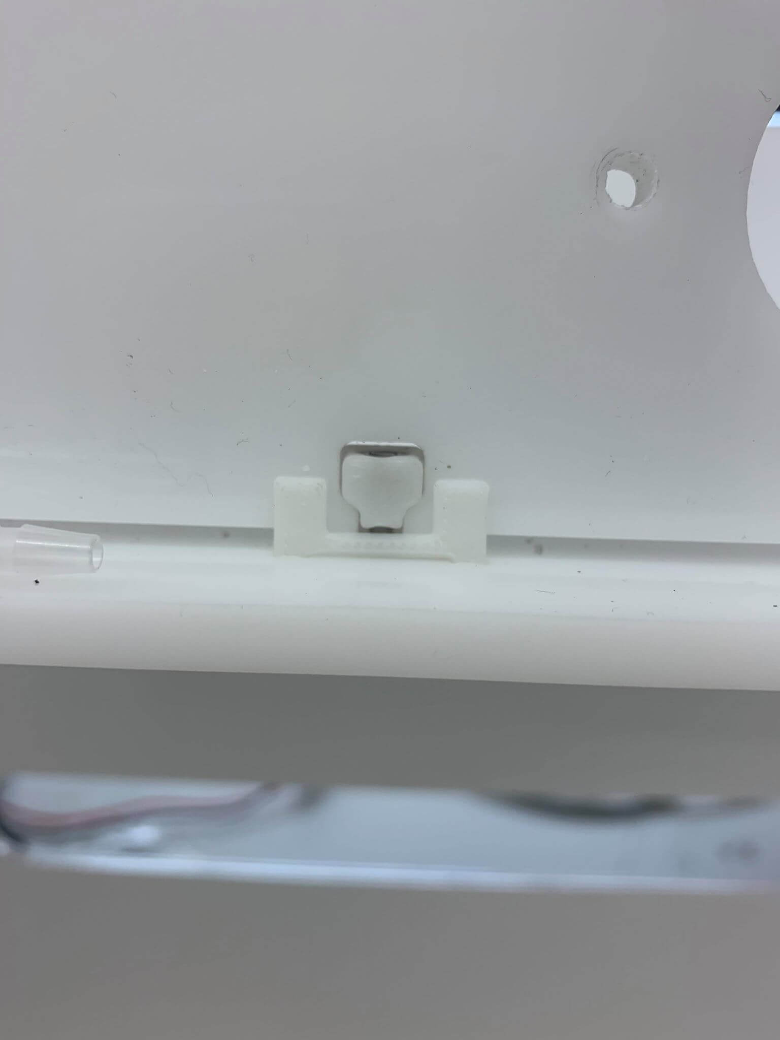
Machine Connectors
The connectors were also pulled from Jake's CAD design
Purchased Materials
- 1 Magnetic Bar Stirrers ($8.99)
- 4 Peristaltic Pumps ($39.20)
- 1 Silicone Tubing ($10.89)
Total Cost: USD $59.08
Fabrication
Cup and Motor Holder
These parts were 3D printed
Machine Frame/Chassis
These parts were laser cut in acrylic
Gantry/Linear Movement
These parts were laser cut in acrylic using the CAD
Machine Connectors
These parts were 3D printed and assembled with a bolt
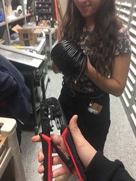
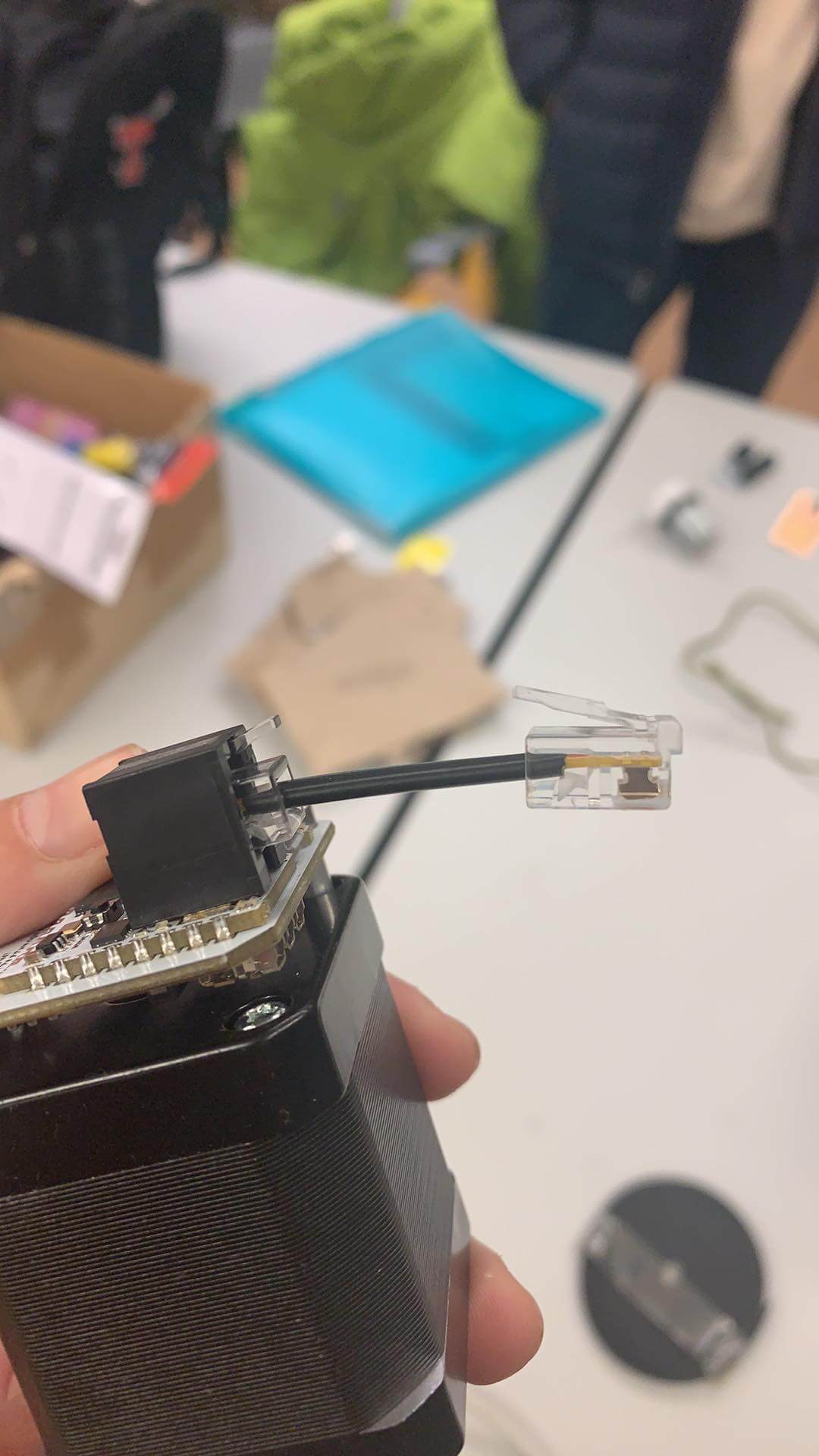
Telephone Cords
These parts were created through cutting ~10 inch wires, stripping ~1cm off of each end, inserting them into a 4 pin tool, and crimping them. The parts were then tested with a multimeter to ensure connectivity.
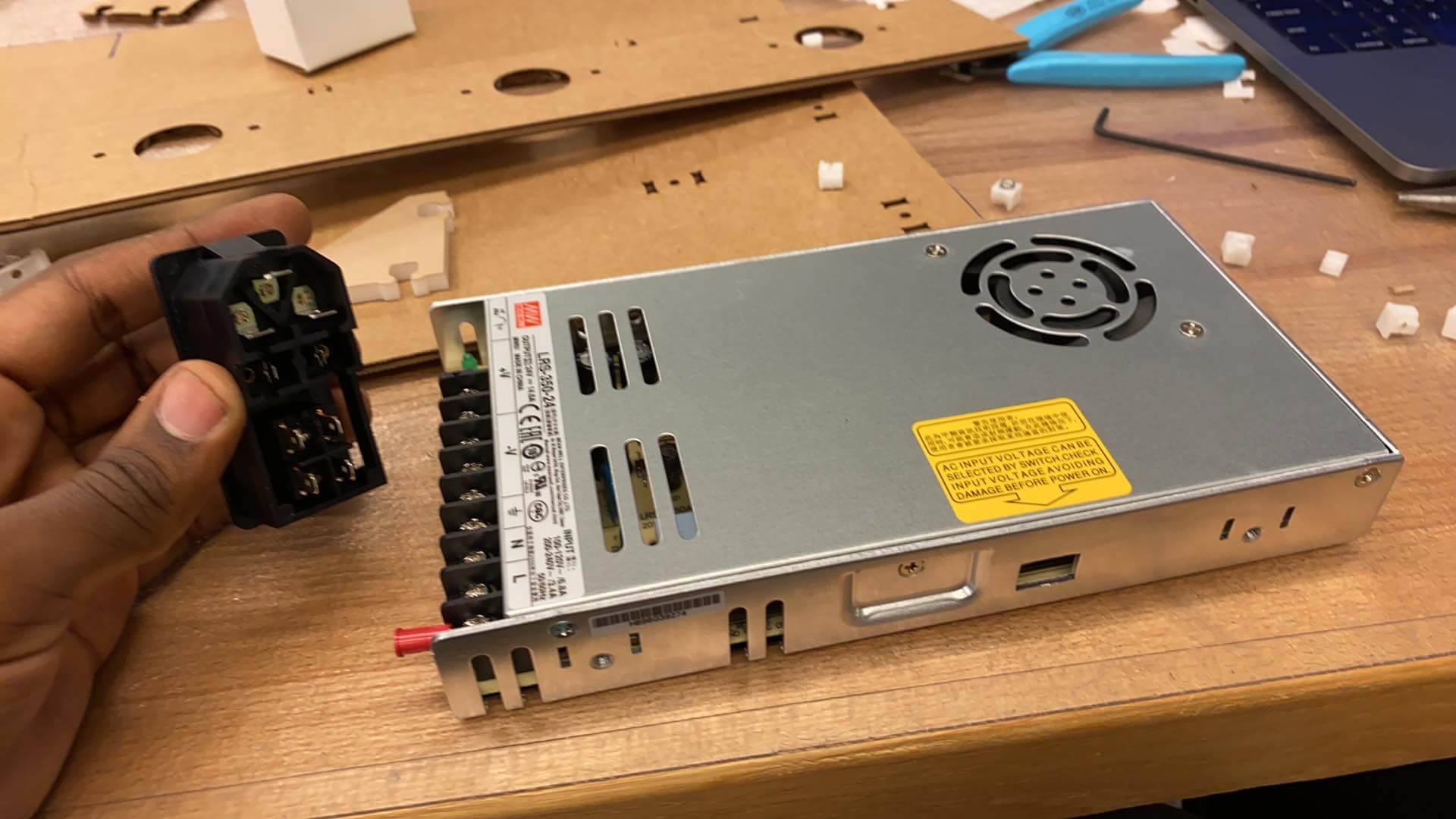
Power Supply Mount
This part was provided by Jake, and thus it was not necessary to CAD/fabricate a new one. The part was then wired successfully.
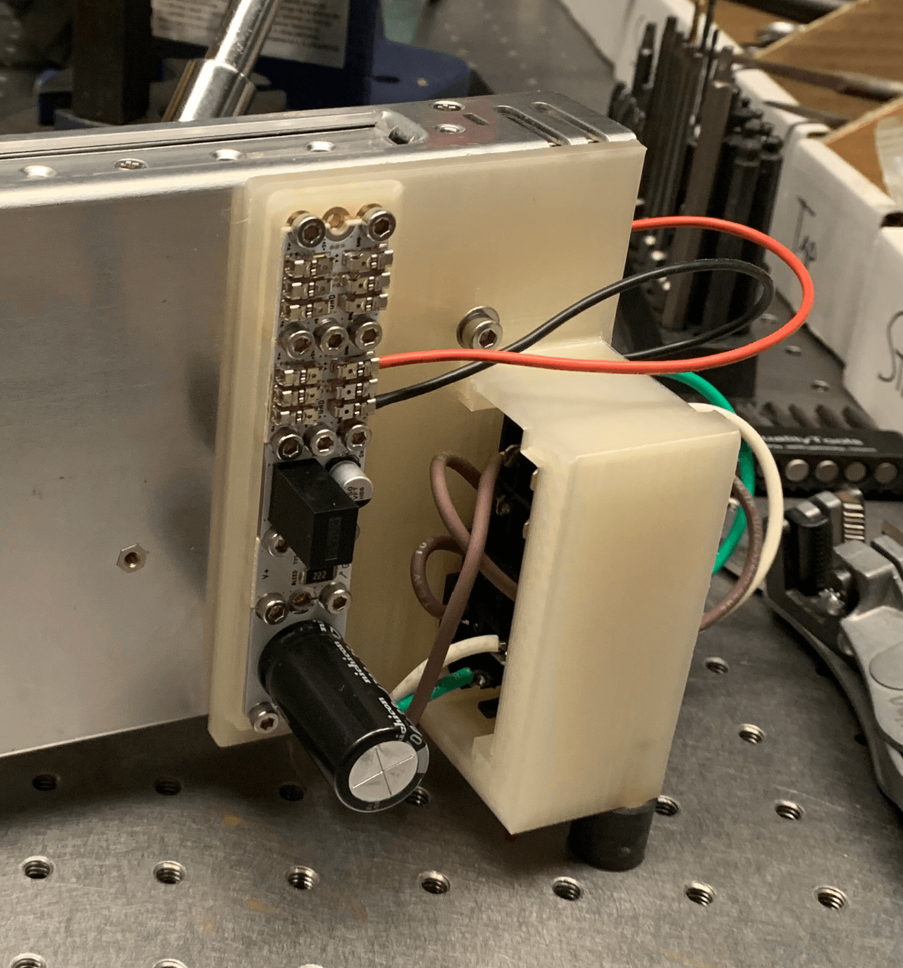
Electronics
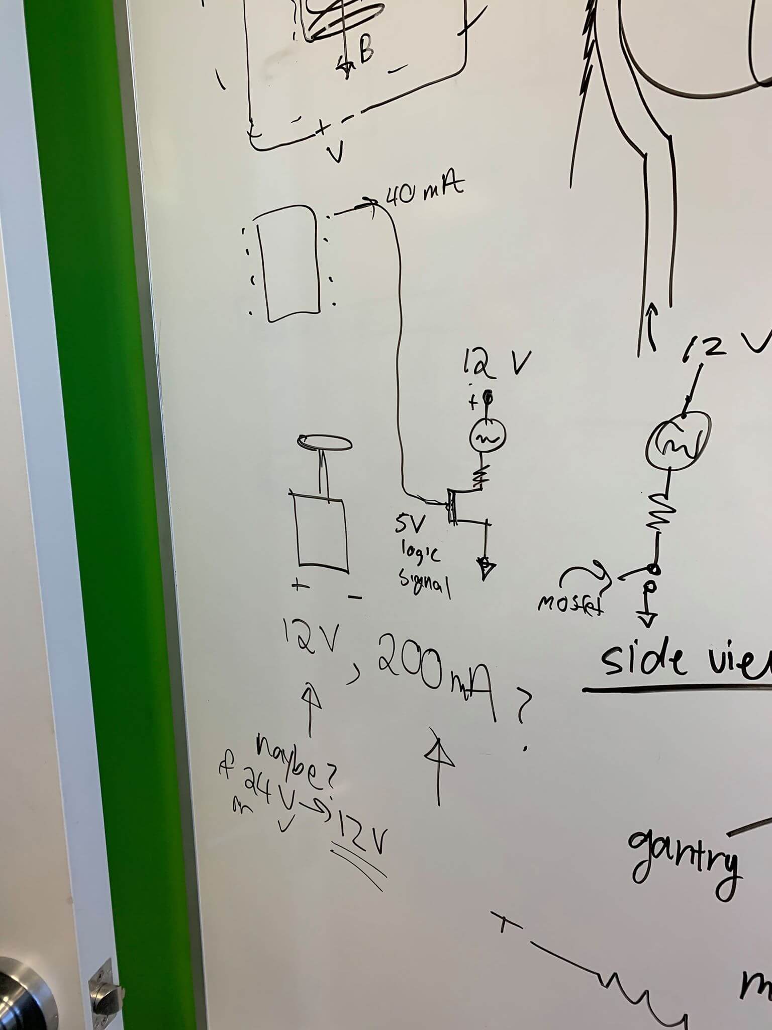
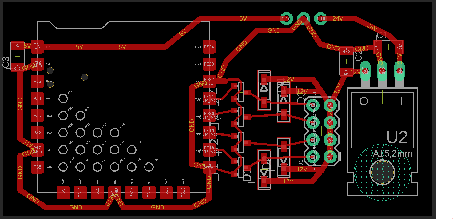
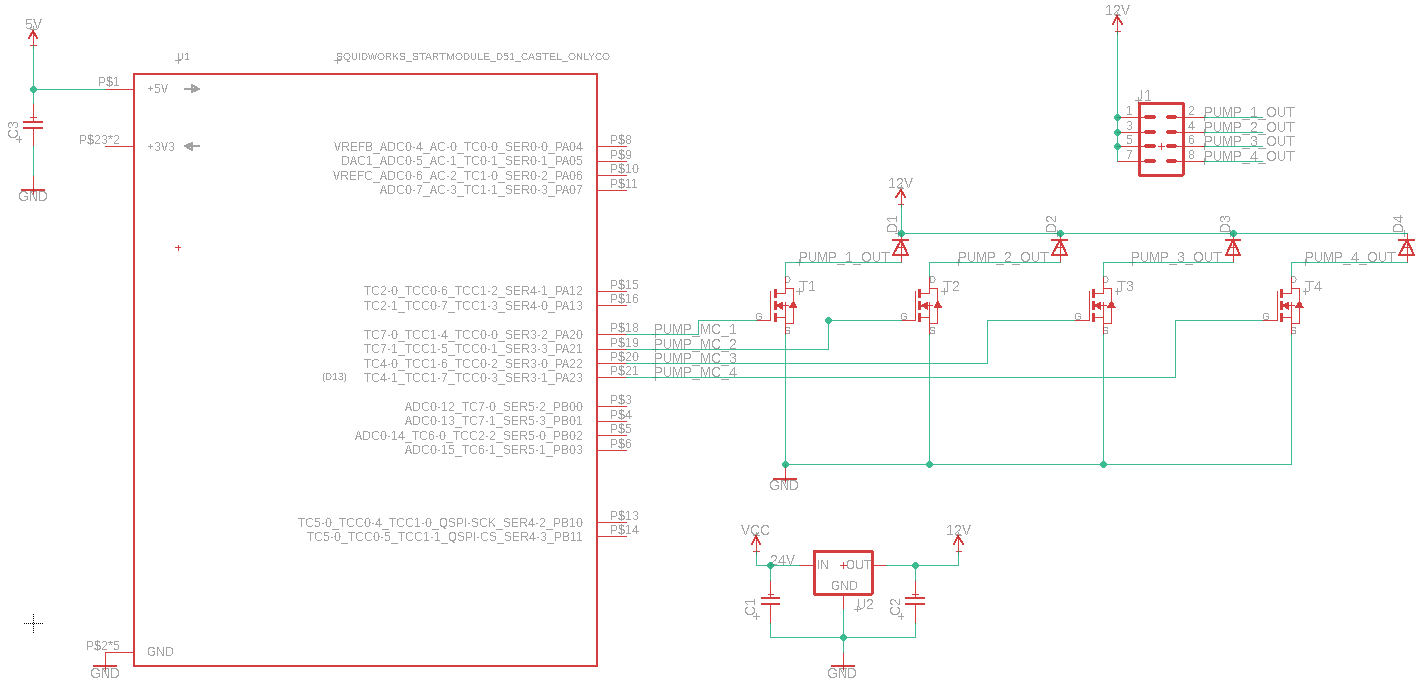
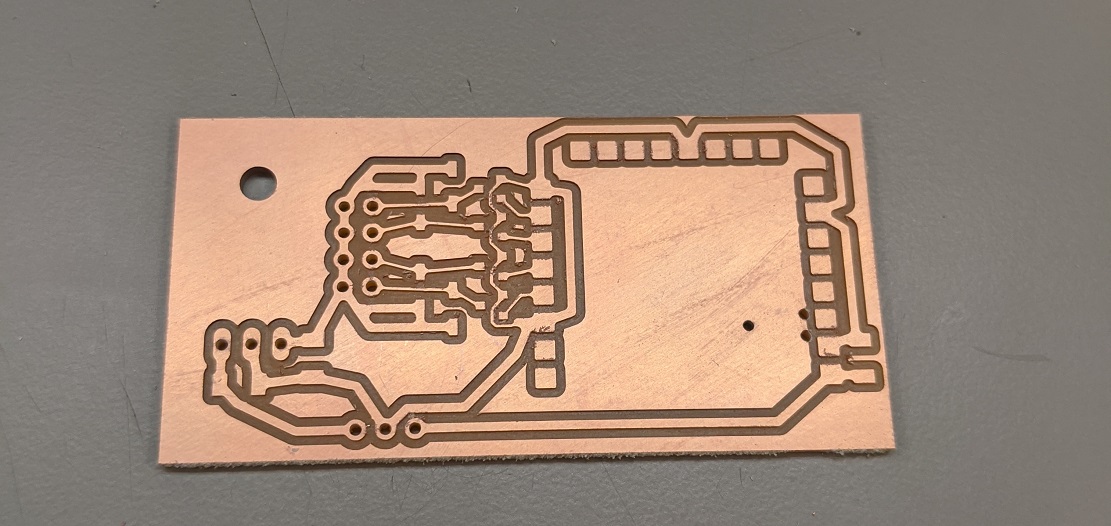
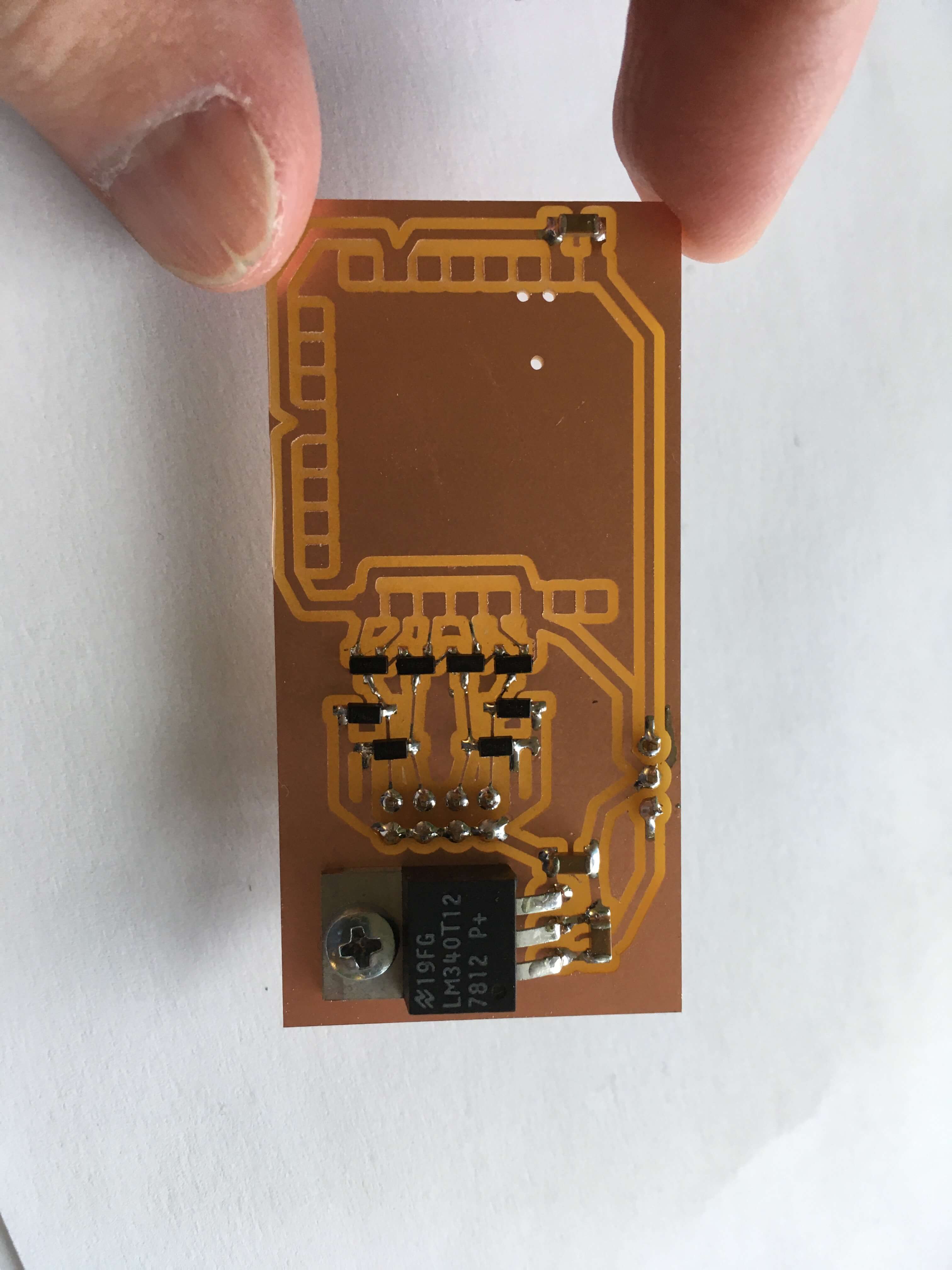
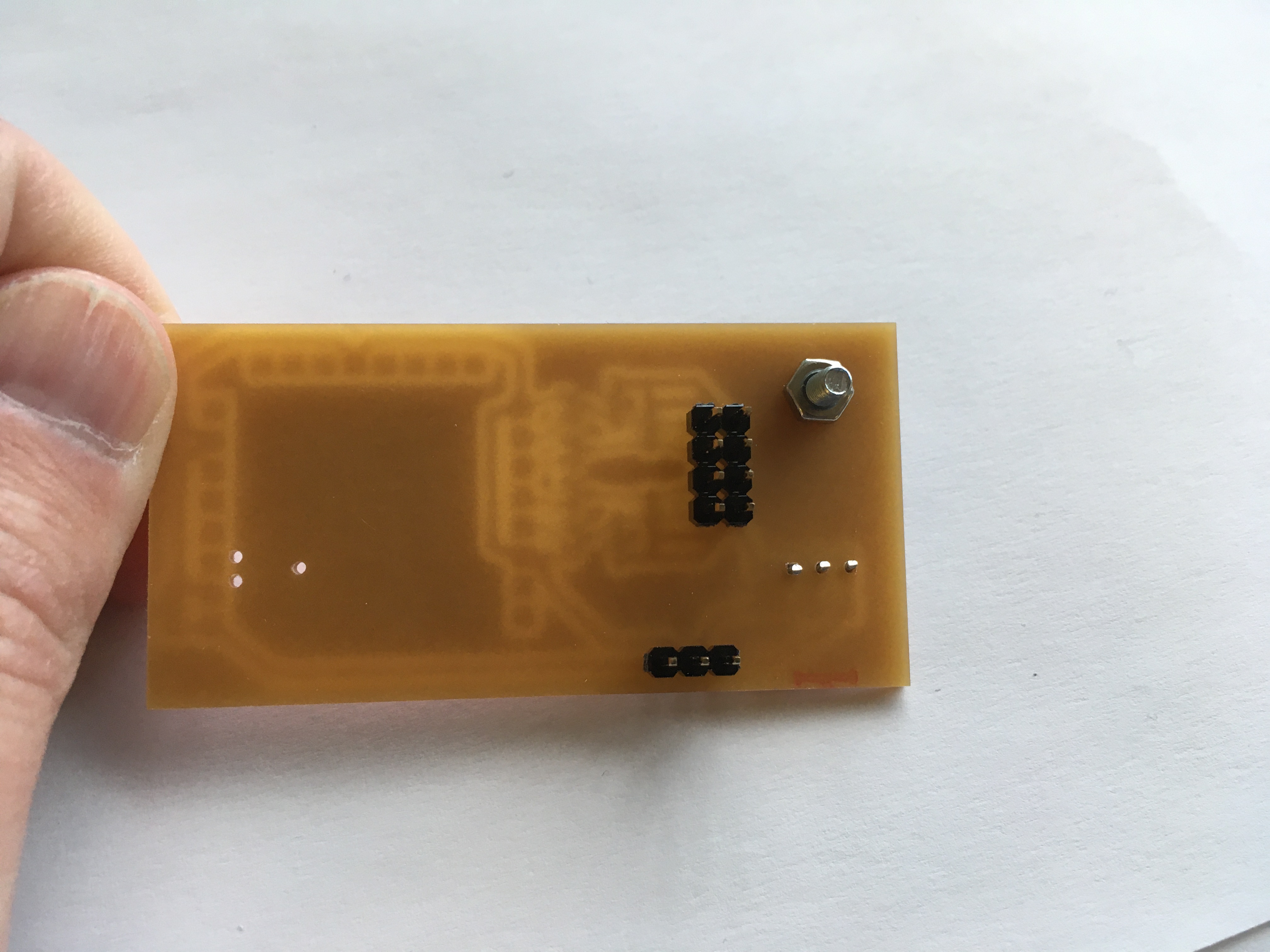
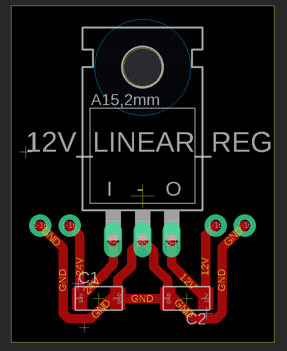
DC Motor Control Board
The board was revised (from what?) and includes the addition of a 12V linear regulator (power from supply is 24v). Routing was added for 5V power to the module board, as more power means more capacitance. The board was then milled and soldered
Drink Stirrer Board
The power board for the stirrer is just a linear regulator, and there’s a switch attached to it.

Software
Low Level Firmware to be Added to Jake's Module Board
Firmware was added using platform.io . Important ponyo files:
- atsamd51j19/src/hunks/pins/hunk_pin_pa12_output.cpp
- ponyo/atsamd51j19/src/build_bootstrap.h
PlatformIo and ponyo setup:
- Add hunk class (example code hunk_pin_pa12_output.h, hunk_pin_pa12_output.cpp) and add to build_bootstrap.h
- Upload code to Jake's board
- Create .js code for hunks, under :cuttlefish/hunks/interface
- Add hunks with inputs and outputs connected to toggle and errlight to output to LED
Code example:
		hunklist[hlc++] = "driver/errlight";
		if (type == "driver/errlight"){
			ret = new Hunk_ErrLight();
		}
Writing Jake's code to the module board: (using linux is easiest)
- Download platformio in visual studio code and open Jake's repo called ponyo folder from platformio home (not visual studio). Then start debugging and fix the following things:
- Run this command to change all "arduino.h" to "Arduino.h"
- Check if it worked by running this to search for any remaining "arduino.h"'s:
- Look for this in the code. It's important to do this otherwise things won't compile. You need to comment out SERCOM5_2_Handler and SERCOM5_0_Handler.
- Check your devices in platformio and if it doesn't say 8031, go to cuttlefish/processes/vfpts.js and change the product ID to match whatever your device reads. let pid = '8031'
// need to comment out arduino's instantiation of this,
// platformio keeps these things elsewhere,
// for (windows) this was (the .- proceeding the folder name means it's hidden)
// you'll have to make sure hidden files are exposed in your finder
// users/"<"me">"/.platformio/packages/framework-arduinosam/variants/feature_m4/variant.cpp
To test things, the name of one of Jake's modules was changed as well as the name in the hunks list in the bootstrap file, and it successfully updated in the GUI side.
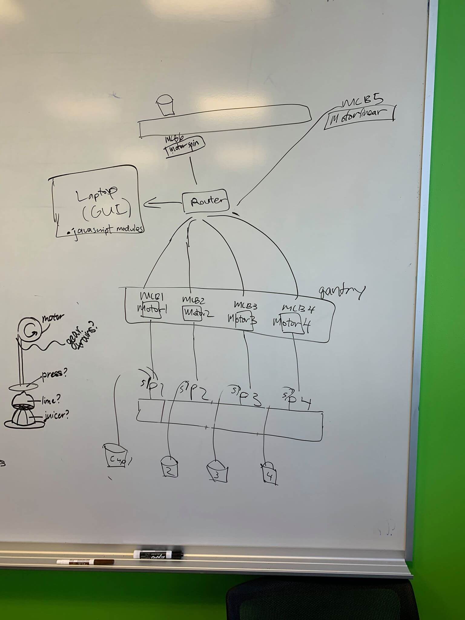
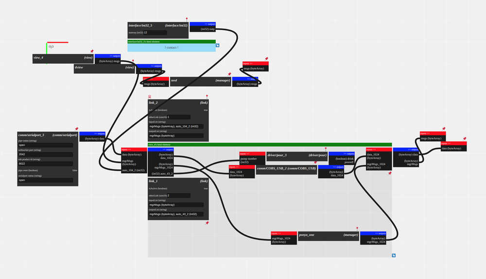
javascript/GUI code interface between cuttlefish and the module board/stepper motor board
Repository:git@github.mit.edu:premila/eds_cuttlefish.git
Cuttlefish:link - connecting the serial port hunk to your computer to interact with boards. Defining pins:
        #define PUMP1_PIN 20
	#define PUMP1_PORT PORT->Group[0]
	#define PUMP2_PIN 21
	#define PUMP2_PORT PORT->Group[0]
	#define PUMP3_PIN 22
	#define PUMP3_PORT PORT->Group[0]
	#define PUMP4_PIN 23
	#define PUMP4_PORT PORT->Group[0]


	#define PUMP1_BM (uint32_t)(1 << PUMP1_PIN)
	#define PUMP1_SETUP PUMP1_PORT.DIRSET.reg = PUMP1_BM
	#define PUMP1_ON PUMP1_PORT.OUTCLR.reg = PUMP1_BM
	#define PUMP1_OFF PUMP1_PORT.OUTSET.reg = PUMP1_BM

	#define PUMP2_BM (uint32_t)(1 << PUMP2_PIN)
	#define PUMP2_SETUP PUMP2_PORT.DIRSET.reg = PUMP2_BM
	#define PUMP2_ON PUMP2_PORT.OUTCLR.reg = PUMP2_BM
	#define PUMP2_OFF PUMP2_PORT.OUTSET.reg = PUMP2_BM

	#define PUMP3_BM (uint32_t)(1 << PUMP3_PIN)
	#define PUMP3_SETUP PUMP3_PORT.DIRSET.reg = PUMP3_BM
	#define PUMP3_ON PUMP3_PORT.OUTCLR.reg = PUMP3_BM
	#define PUMP3_OFF PUMP3_PORT.OUTSET.reg = PUMP3_BM

	#define PUMP4_BM (uint32_t)(1 << PUMP4_PIN)
	#define PUMP4_SETUP PUMP4_PORT.DIRSET.reg = PUMP4_BM
	#define PUMP4_ON PUMP4_PORT.OUTCLR.reg = PUMP4_BM
	#define PUMP4_OFF PUMP4_PORT.OUTSET.reg = PUMP4_BM
Added hunk to list in bootstrap
	  hunklist[hlc++] = "driver/pour";
	  if (type == "driver/pour"){
	    ret = new Hunk_Pour();
	  }
We created a state machine that transitions between pouring and moving in a javascript hunk to use in cuttlefish to set the workflow for our machine. We created two outputs: one for the pump number we want to pour out of and one for the position we want our cup to be at.
	// pumpState output -> microcontroller input
	let pumpState = this.output('int32', 'pumpState', 0);
	// stepperPosition output -> saturn posn input
	let stepperPosition = this.output('array', 'stepperPosition', 0);
We initialized the drinking machine hunk:
	this.init = () => {
		this.log('hello drinking machine')
	}
We have a dictionary mapping drink numbers to lists of the ratios/amount of each ingredient for each drink.
	  const dictDrinks = { //apparently you can't have integer keys
	    '0': [0], // a state to reset everything
	    '1': [1,1,2,2,2,4,5], // end with 5 so we go to the end
	    '2': [1,1,1,2,3,3,5],
	    '3': [2,2,2,3,3,4,4,4,5],
	    '4': [1,1,3,3,4,4,4,4,5]
	  };
We also created a dictionary for positions to move to via the stepper motor, with the states below:
	  const dictPositions = { // Pass an array to Saturn
	    '0': [0,0,0],  // far left
	    '1': [20,0,0], // under first pump
	    '2': [40,0,0], // under second pump
	    '3': [60,0,0], // under third pump
	    '4': [80,0,0], // under fourth pump
	    '5': [100,0,0],// far right
	  };

	  const states = {
	    IDLE: 0,
	    GET_NEXT_ITEM: 1,
	    MOVE_STEPPER: 2,
	    MOVE_DELAY: 3,
	    POUR_DRINK: 4,
	    POUR_DELAY: 5
	  };

      //We used a delay technique to wait for different states to finish:

	  const delayInMillisecondsMove = 1000; //3 second
	  const delayInMillisecondsPour = 2000; //30 seconds


       //Here's the list of drinks we can make for you!

	    const pairList = [
	      [0, 'Reset'],
	      [1, 'Mojito'],
	      [2, 'Manhattan'],
	      [3, 'Screwdriver'],
	      [4, 'Tropical Sunset']
	    ];

      //This is the loop that switches between states:

	  this.loop = () => {
	    switch(state){
	      case states.IDLE:
	        // do nothing while idling
	        break;
	      case states.GET_NEXT_ITEM:
	        // check to see if there's anything left to grab
	        if (currentIngredient >= drinkList.length){ // nothing left to do!
	          state = states.IDLE;
	          console.log("Drink Complete");
	          break;
	        }
	        // pull the next drink
	        let oldMove = curMove; // check previous move to see if we've done it already
	        curMove = dictPositions[drinkList[currentIngredient]];
	        curPour = drinkList[currentIngredient];
	        console.log("Preparing ingredient " + currentIngredient);
	        currentIngredient++;
	        if (oldMove == curMove) { // if we've already moved the stepper here, don't do it again
	          state = states.POUR_DRINK;
	        }
	        state = states.MOVE_STEPPER;
	        break;
	      case states.MOVE_STEPPER:
	        stepperPosition.put(curMove); // move the stepper
	        console.log("Moving to " + curMove);
	        setTimeout(function() { // after 3 seconds, switch to pour state
	          state = states.POUR_DRINK;
	        }, delayInMillisecondsMove);
	        state = states.MOVE_DELAY;
	        break;
	      case states.MOVE_DELAY:
	        // do nothing while waiting for move to complete
	        break;
	      case states.POUR_DRINK:
	        if (curPour == 5){ // don't pour if we're at the end
	          state = states.IDLE;
	          console.log("At the end, no pour");
	          break;
	        }
	        console.log("Pouring " + curPour);
	        pumpState.put(curPour);
	        if (curPour == 0){ // there's nothing to pour
	          state = states.GET_NEXT_ITEM;
	          break;
	        }
	        setTimeout(function() { // after 30 seconds, switch to get
	          pumpState.put(0); // stop pouring after complete
	          state = states.GET_NEXT_ITEM;
	        }, delayInMillisecondsPour);
	        state = states.POUR_DELAY;
	        break;
	      case states.POUR_DELAY:
	        // do nothing while waiting for pour to complete
	        break;
	    }
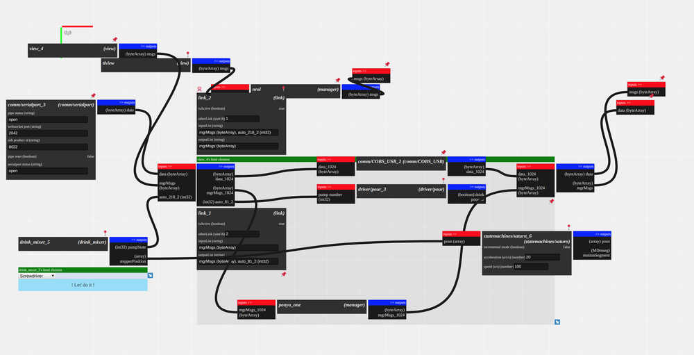
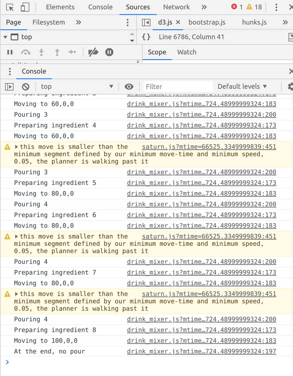
The GUI for one drink, cuttlefish saturn pump success, and the successful state machine are below:
Assembly
After fabricating all of our parts we ended up assembling them we realized the cup holder was too tall to fit in the chassis correctly. We ended up adding this to the side of the machine to hold the cup for magnetic stirring and fabricated another shorter cup holder to go in the chassis. We then tested the product without the holder (with duct tape) while we waited for the part to print. We hooked all the pumps up and covered everything with electric tape.
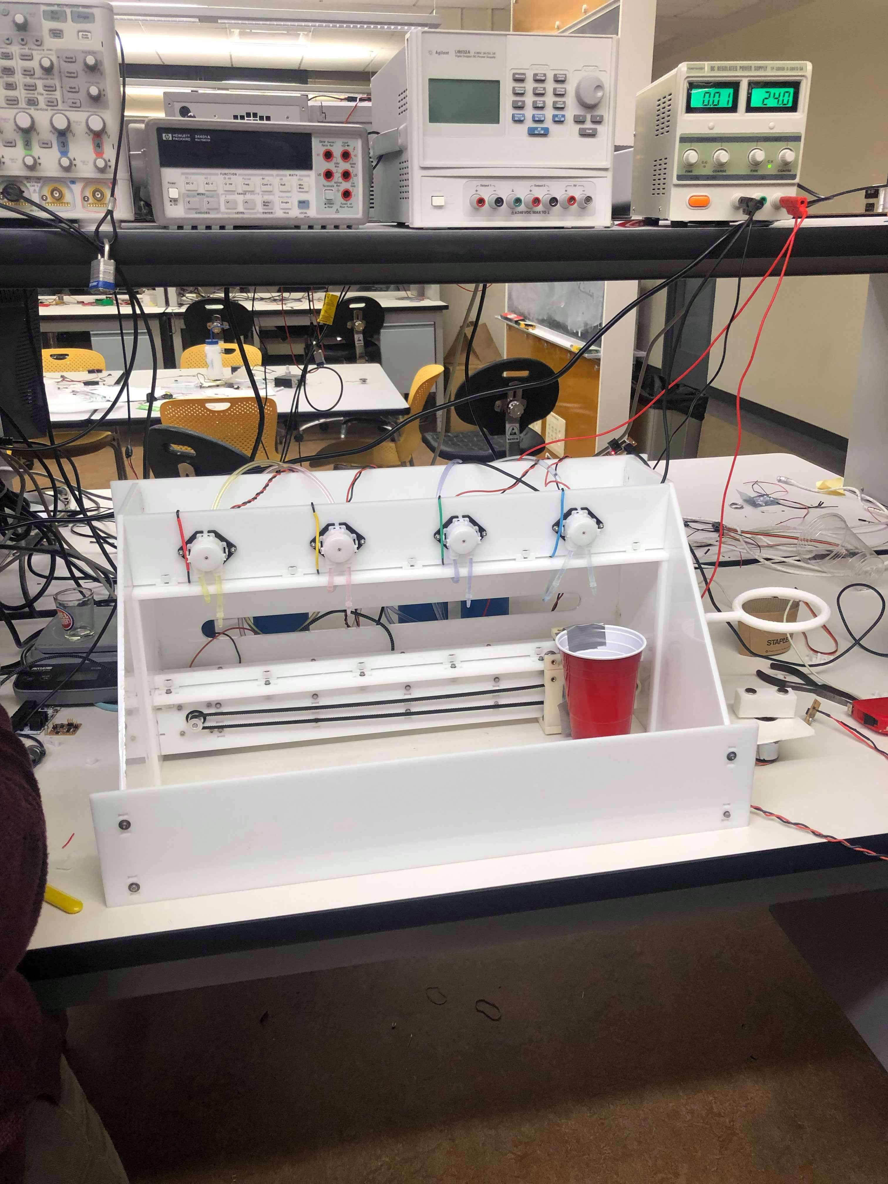
Testing
We first tested the silicone tubing and magnetic stirring
We then tested the gantry and the pumping of liquid together. The first build failed due to another program not being started. The second build succeeded and we successfully made the drink "Green Monster"
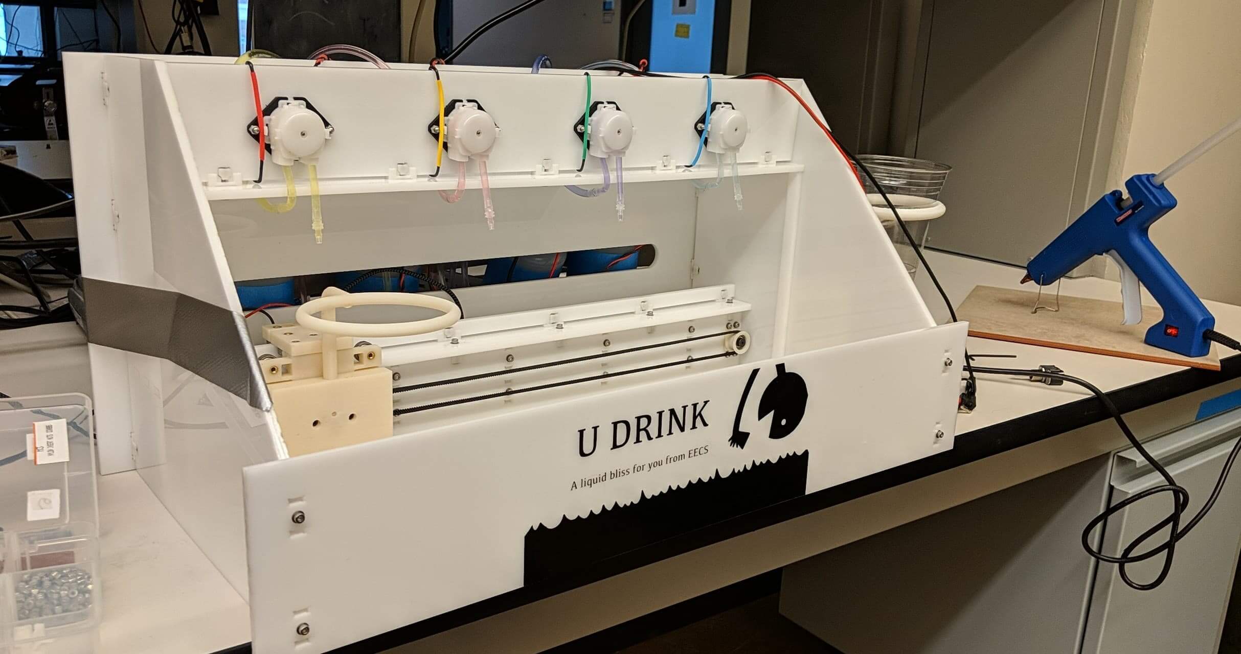
Final Product
Introducing UDrink!