Week 6: Embedded Programming
This week, we learn how to program the microcontrollers! Throughout the class, we've been building random boards and loading them with instructions written in some esoteric file descriptions. This week I wanted to erase some of this mystery and figure out how the system actually worked.
To start with, I took the board I had milled for Electronic Design. Using a guide on the Make website, I tried to load a simple program onto the board.
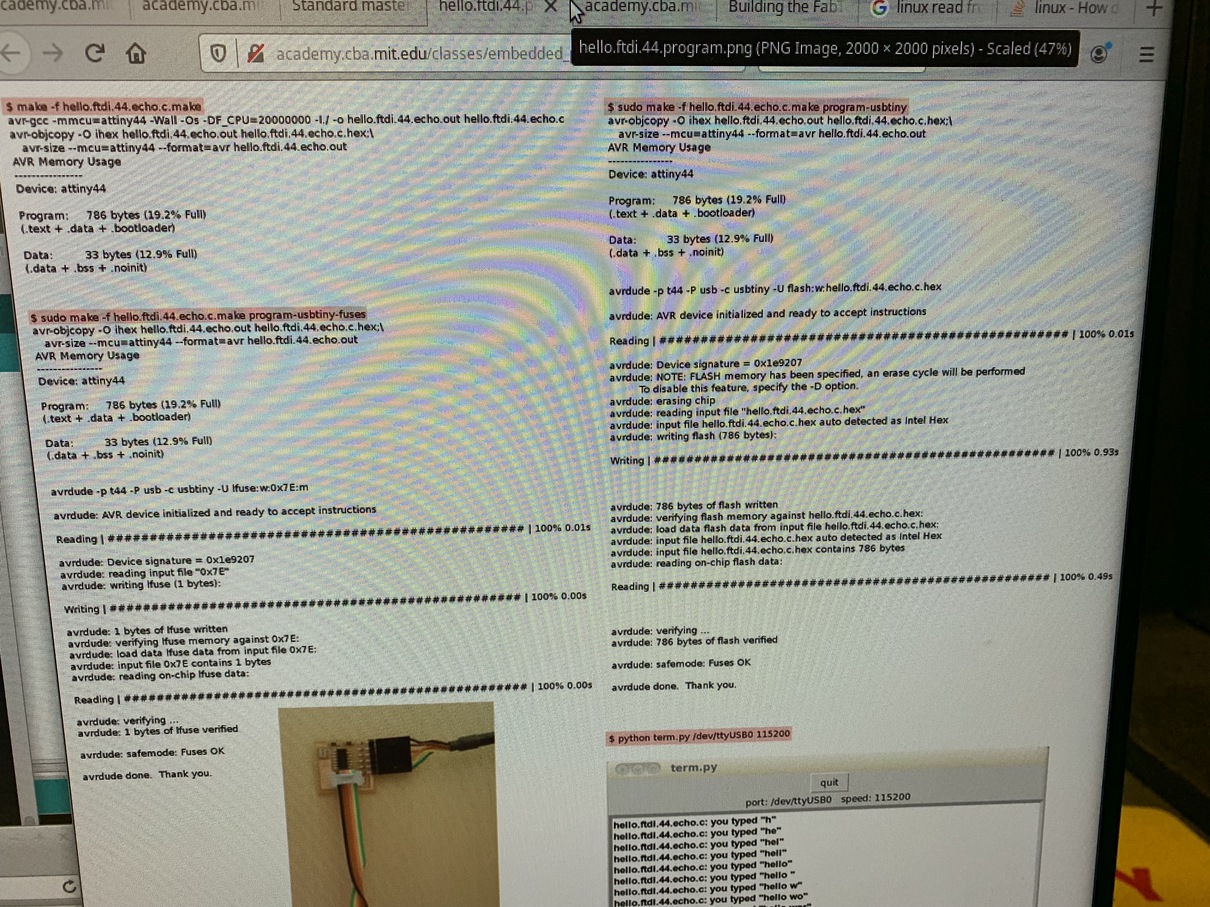
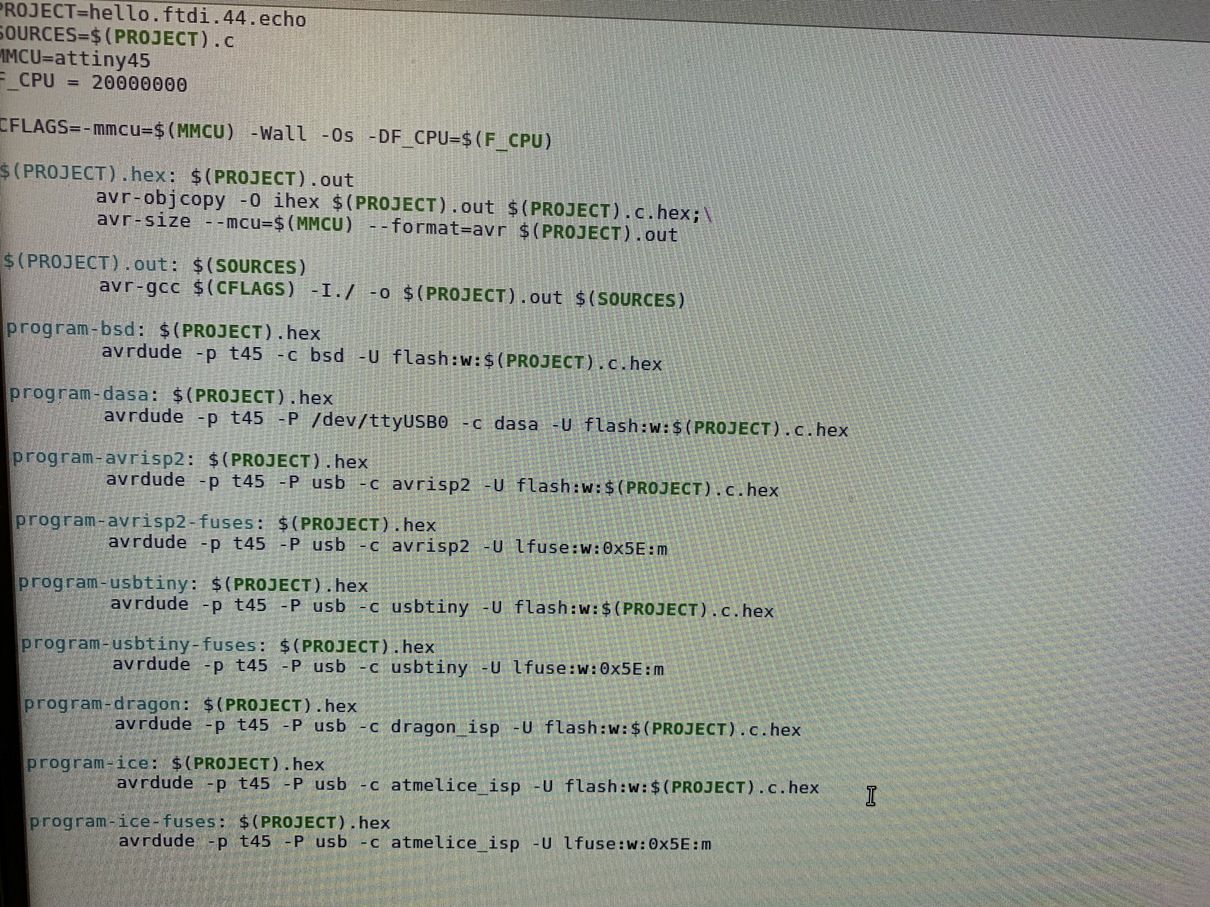
The first thing to do was download the C code and make the project. I checked out the make file to see how everything was working internally. Basically, the top of the Makefile specifies what microcontroller we are building for, and it was very important to get this right. The rest of the build targets basically just use variants of avrdude depending on what programmer we're using. Since I was using my own programmer from earlier in the class, I used the usbtiny option.
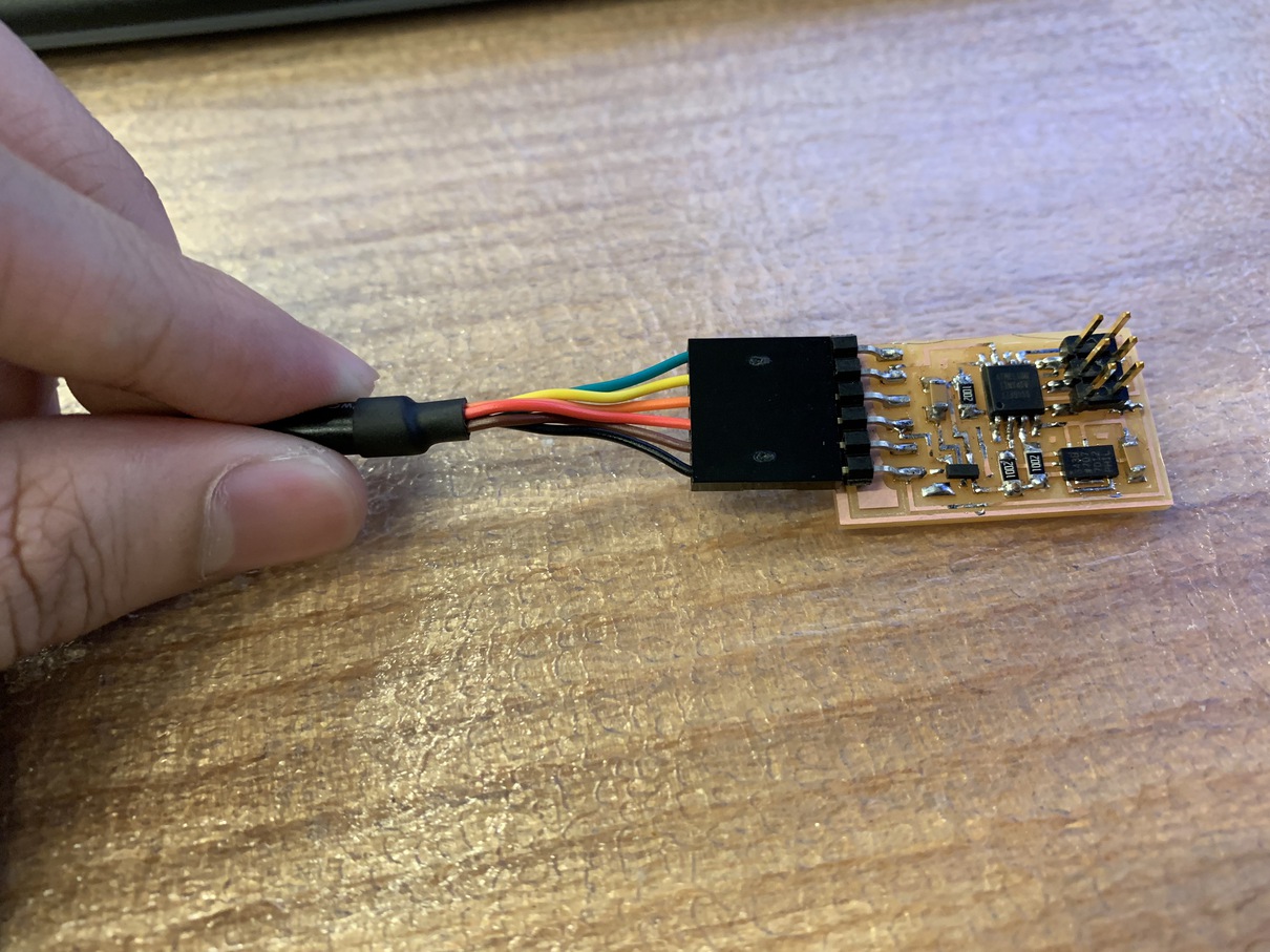
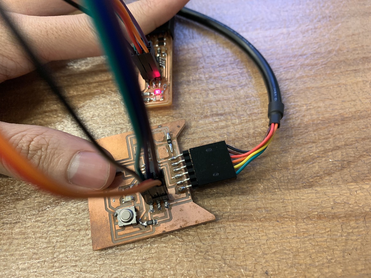
To actually hook up the cables, I had to connect the programmer to my computer via an FTDI cable. I found out the orientation by looking at the pin diagram for the programmer and matching up the volt and ground pins. It turns out that one pin carries voltage and one carries ground, and the rest are all carrying signals from the host (my computer).
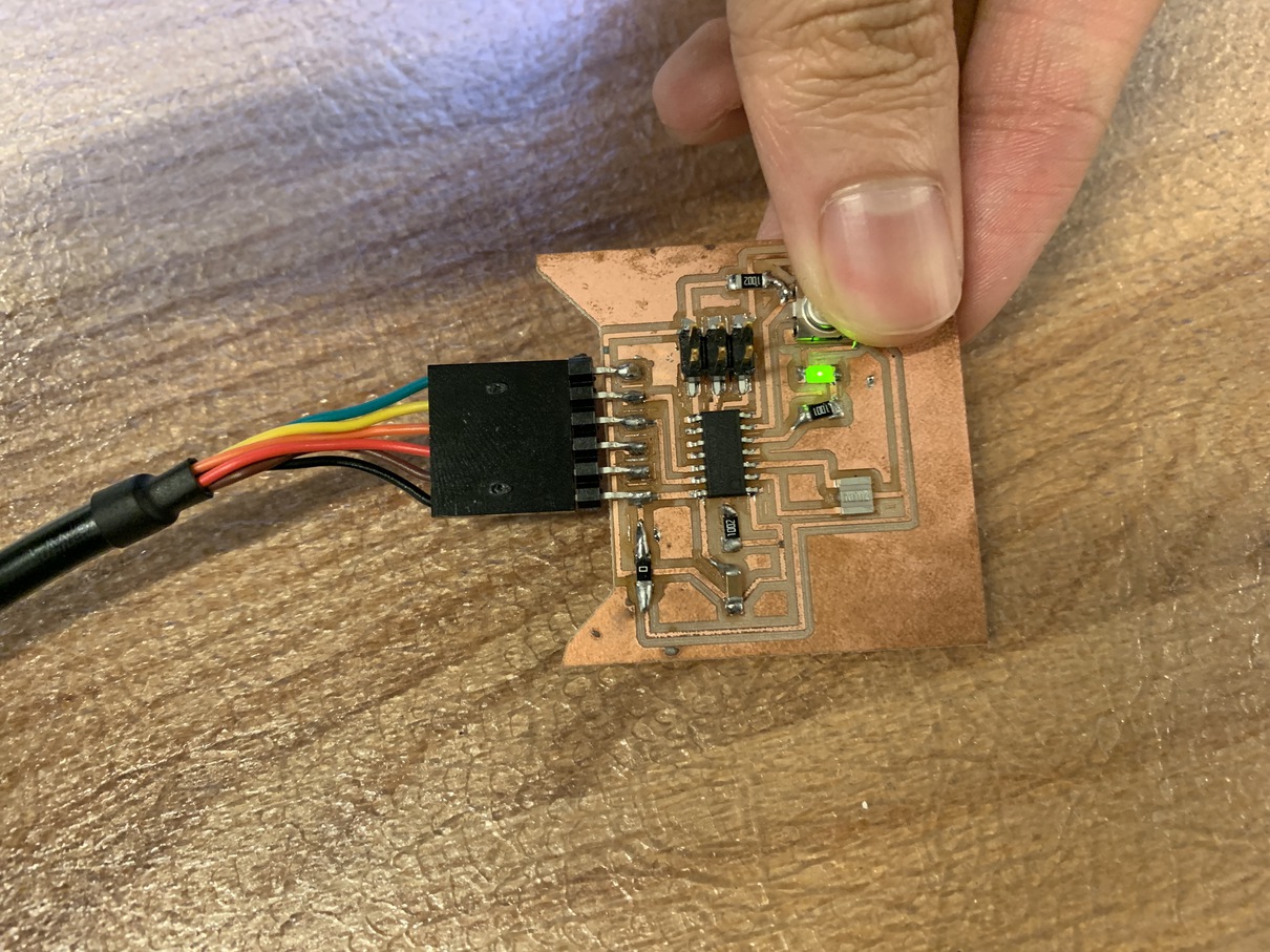
Next, I had to connect the programmer to the board. This uses the six-pin pinout located on both of the boards, which always follow a standard layout, but it is important to make sure the pins are not rotated 180 degrees or the programmer won't be able to see the board. Finally, I also had to power the board itself -- in this case, I didn't need to connect all six of the pins FTDI-style, but only the voltage and ground pins.
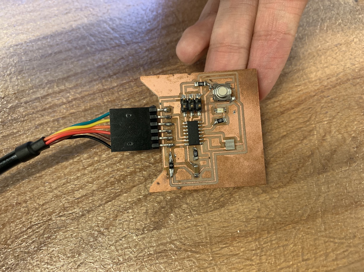
With that, the board was working and could light up the LED when the button was pressed! This week was mainly a simple test to setup the pipeline of getting a board programmed. For some more advanced board programming shenanigans, see my week on Input Devices.