Week 8: Input Devices


This week on How to Make, we start the components of the final project! The idea I have is to build a motorized wooden shrine. In traditional Japanese custom, a visitor uses a shrine by first offering a coin into a donation box. This week, I wanted to build an electronic donation box that could track when a coin was inserted.
I already had built the shell of the box out of wood, which actually posed a nice challenge as I couldn't modify the design to account for the need for sensors and wires. Using a chisel, I pried open the side of the box which I had wood glued shut earlier to reveal the inside.
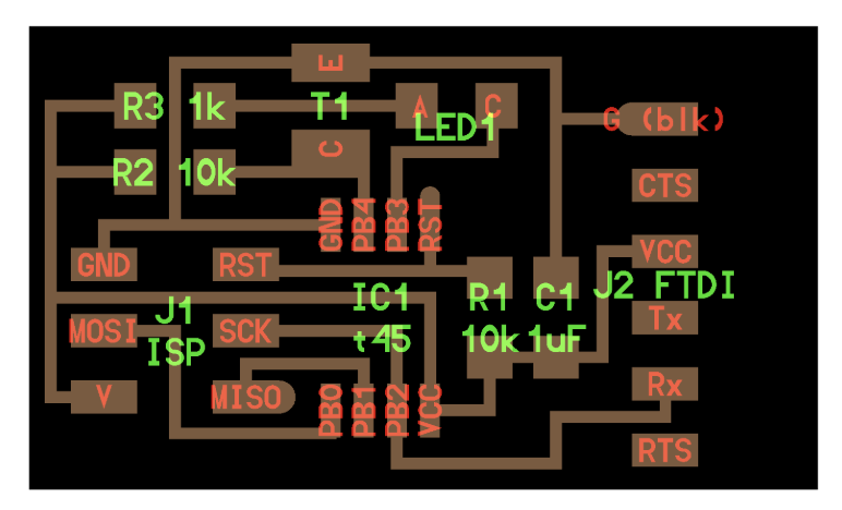
After going over some options, I decided to use an infrared sensor along with an LED to detect when the coin fell into the box. More modern coin detectors use magnetism or a laser, but they usually route the coin into a thin corridor through mechanical means, like in a vending machine slot. Since my box was already so size-constrained, I needed to use a detection method that would still work over a large area. I started out with the "light" board from the Make website.
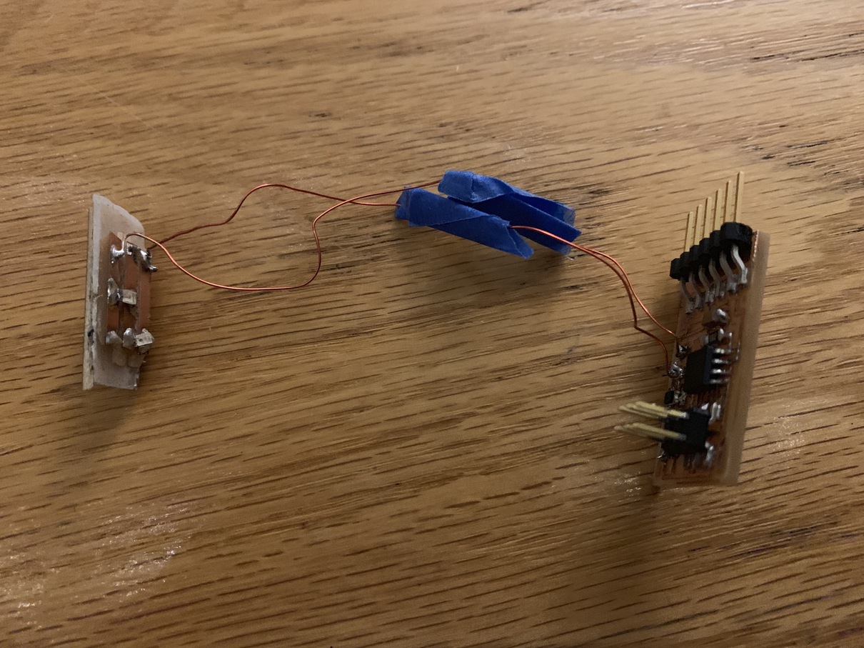

The default board has the LED and the photoresistor in roughly the same location, and basically relies on the reflection of an object to track if something is in front of the sensor. While this works in close range, I found it very hard to detect objects greater than a few milimeters away. To solve this, I soldered an extension wire where the LED should have been on the traces, and instead powered a remote LED which would go on the other side of the box. If a coin falls through, it would block the light from reaching the sensor for a few moments, and I could capture that.
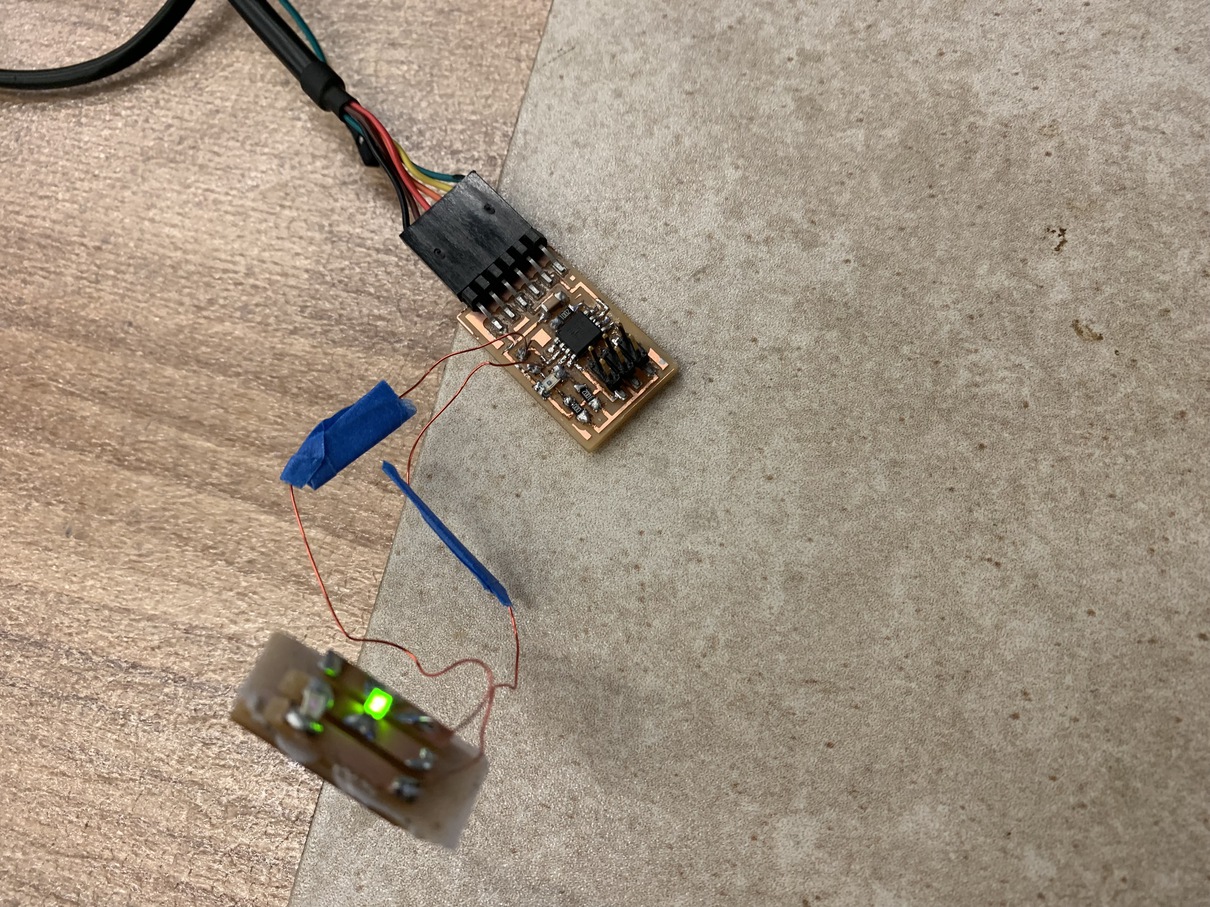
As it turns out, it's really hard to debug when using an infrared light, since infrared is by nature invisible to humans. To solve this, I added a second LED to output green light as a sanity check that the LEDs were outputting anything at all. In the first iteration of this, I had them in parallel, but it made the lights output a very dim light. By putting them in series the current passing through would not be as limited so the lights could shine much brighter.


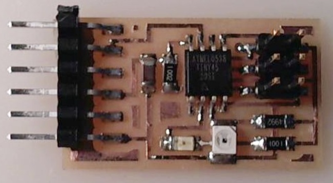
I think the biggest nightmare in getting this setup working was the programming. A few weeks ago I had learned the embedded programming pipeline, but what worked in the simple case encountered a lot of friction this time around. My avrdude refused to recognize the board, and it seemed like every att45 would not be seen by the usbtiny programmer, while the att44 boards were just fine.
It turns out that it was simply a coincidence, and the att45 boards I was using to test both had faults in their traces which caused the circuits to behave incorrectly electronically. After remaking the board, and making sure to align the pinouts and FTDI cables exactly the right way, I was able to write to the board!

I also learned a ton about how the C code used to program the boards operates. The lines above are a good example. As it turns out, PB2 and PB3 are constants defined in the AVR library, representing the bits corresponding to the output pins of the microcontroller. By bit shifting a 1 to these locations, we can essentially refer to the pin in code, and use it wherever it is needed, such as turning on the LED or reading from the IR sensor.
Once the base system was setup, there were still some problems to work through and fix. I could detect the light and read from the sensor, but only at a close range. I had to increase the brightness of the LEDS, and also increase the sensitivity of the photoresistor, to make the sensor more responsive. This was achievable by swapping out the resistors for smaller values so that the voltage range the microcontroller was reading/writing could be more spread out.

Finally, after many many hours late into the lab, the detector was working! I could read the values of the photoresistor directly from my computer through an FTDI cable, and it was a strong enough sensor to detect objects up to a few inches away.