Week 9: Input Devices
The input device I wanted to use this week is a quadrature encoder. I got a DC motor with an encoder from a friend so I'm not sure what the exact model is, but this datasheet has a matching pinout so I used this to figure out the connections I needed.

Designing the board
I wanted to use a attiny44, A4953 motor driver, and include a FTDI header on my board. In my first design, I accidentally connected the encoder pins to the motor driver instead of the attiny. I fixed this and made sure that the motor power pins were connected to the output of the motor driver. Here is the schematic and board that I designed using Eagle:


Milling the board
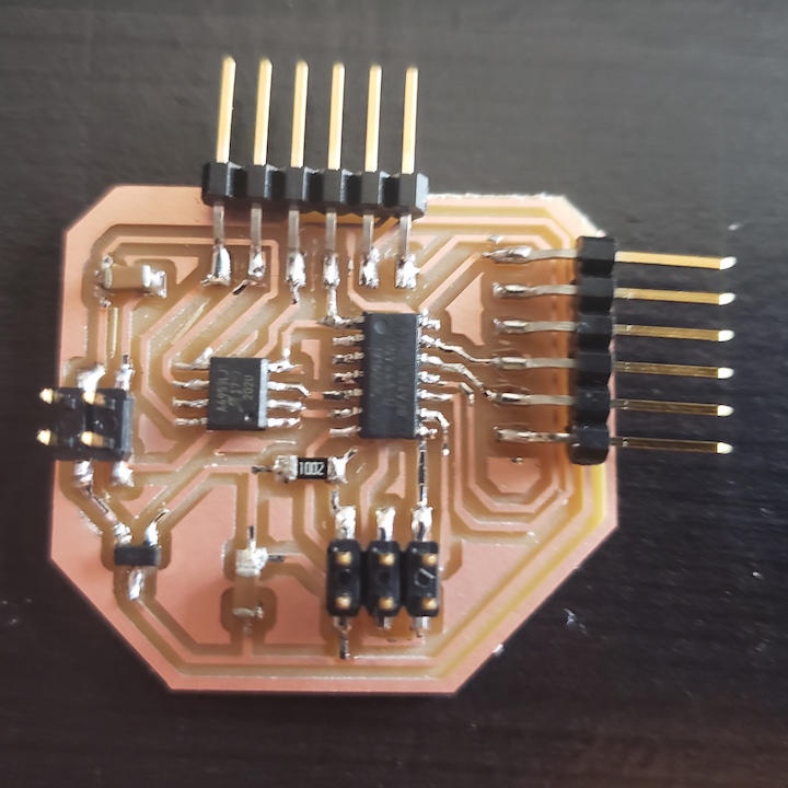
I think the many boards I've made for this class so far have paid off because I milled and stuffed the board correctly on the first try. The 6-pin header on the top is for the motor connection and the 6-pin header on the right side of the board is for the FTDI connection. Since I am powering the board with a 9V battery and stepping down the voltage using a 5V voltage regulator, I don't need the 5V from the FTDI connection.
Programming the board
Just to verify that the board was working, I first programmed the motor to spin. I used the Arduino IDE for this and just used the program I for the embedded programming week.

Then, I had to tackle the challenge of handling serial communciation. Since I am using the attiny44, I have to do all my communication through the SoftwareSerial library. I started off with the example software serial code example to just try to get readable output to show in my serial monitor. I had to play around with baud rates and clocks. The setting I found that worked was internal 1MHz clock speed and 9600 baud rate.
I switched back and forth between a machine running OSX and a machine running Ubuntu. One issue I found on the Linux machine was that my user didn't have permissions to open the serial port. To solve that, I had to change permissions on the port (/dev/tty/ACM0 on my machine) to allow access: $ sudo chmod a+rw /dev/ttyACM0

Once I could print out characters to the serial monitor, I wrote up a program that would read in the encoder values and increment or decrement a counter depending on the direction of rotation. The code is pretty simple and here's a video showing the counter increase as I turn in one direction and decrease as I turn in the other direction.
Since I need accurate and steady motor speed control for my final project, I plan use the encoder values to set up a PID control loop next week for output devices so stay tuned.