Concept
I want to make a sand table that is constantly changing. The initial conecept came from this video linked below. The idea is centered around having a table sitting with fine sand in it. There is a magnetic ball on the top of the sand that continuously moves around based on the electronics hidden below. The table will be made to look like there is nothing but a wire connected to it for power. On the inside should be sand that is covered in a glass plate and the ball inside. Youtube link
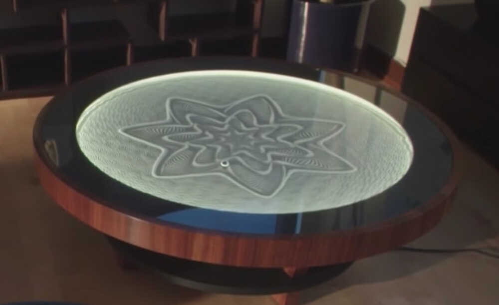
Table concept
Designing
First I have made some sketches of what the table should look like. I want the table to be wooden and ideally stained or painted in the end to look more interesting. The electronics and the insides are the harder part of this project. I need to have a 2 axis contraption below that will be moving the magnet to move the ball--I am initially thinking it will move similar to watching a 3D printer operate (but only in 2D). If the material the sand is sitting on is thin and the sand is not too thick then the magnet that is attached to the moving axis will pull the ball magnet along the sand.
Initial Sketches
Thoughts about the initial setup of the machine
Sketch of the proposed arms
Sketch of the proposed arm movement
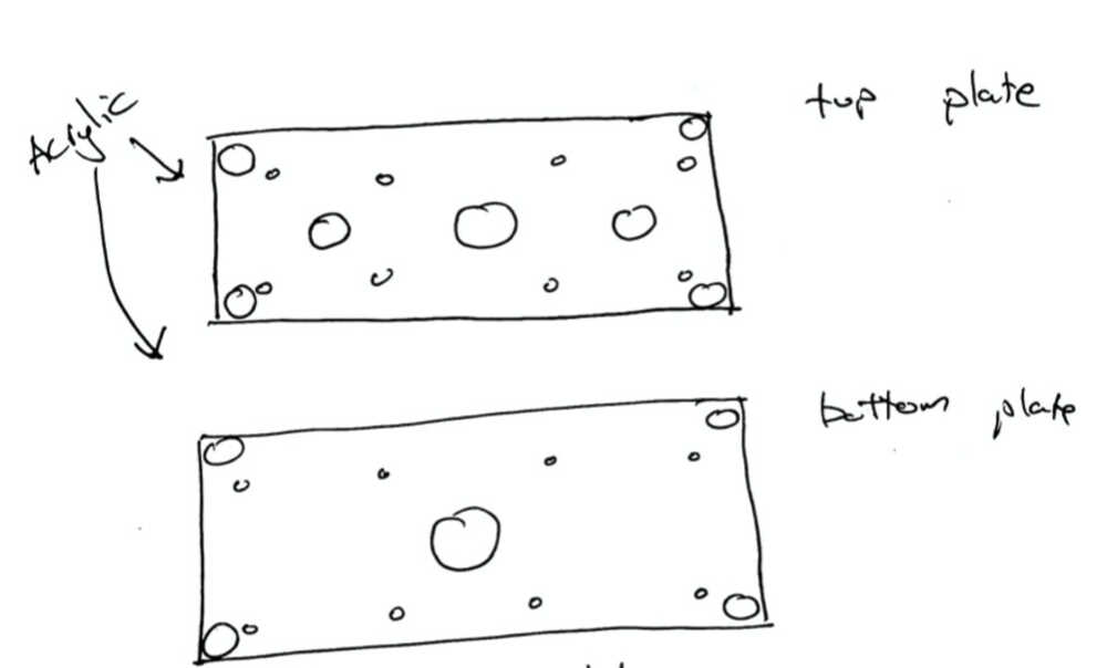
Sketch of the plates
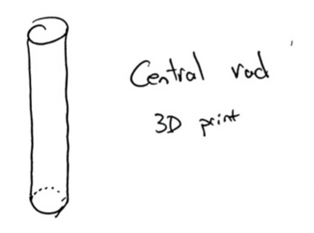
Sketch of the proposed rod
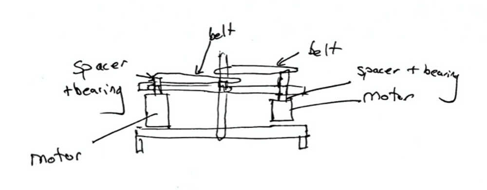
Sketch of the proposed machine from the side
Designing Parts
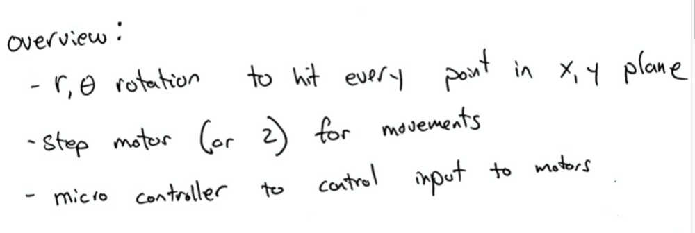
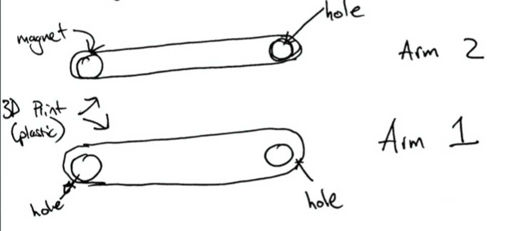
I am in the stage of designing many parts and seeing how they will fit together. I have come to the conclusion that the cordinate plane we will be using is radius and radius. There will be 2 different arms that are controlled by 2 step motors. One arm comes out of the center and is on a belt from motor 1. This arm only spins in a circular motion. The second arm is attached to the first arm at the end and to motor 2. This arm does the same rotation to come up with the other part of the radius to be able to hit every spot on a circle with the magnet. The magnetic spot is at the end of arm 2.
Arm 1
Arm 1
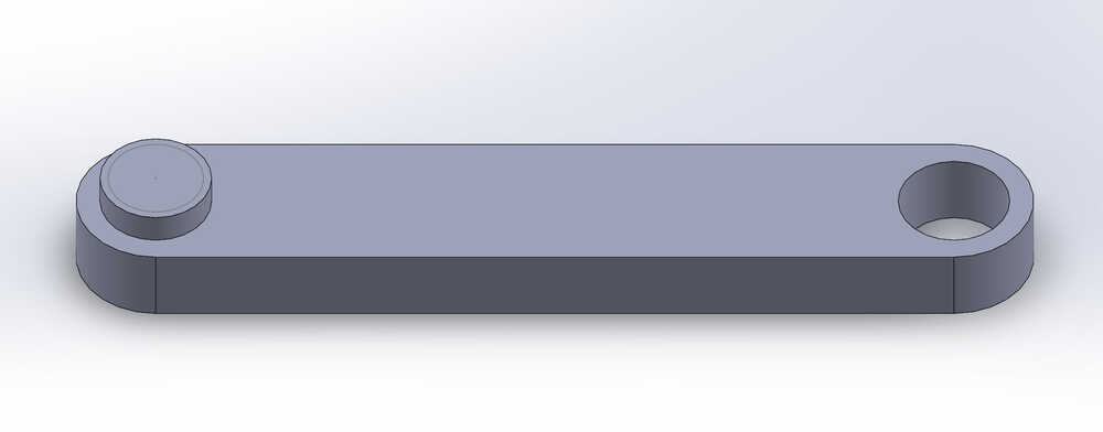
Arm 2
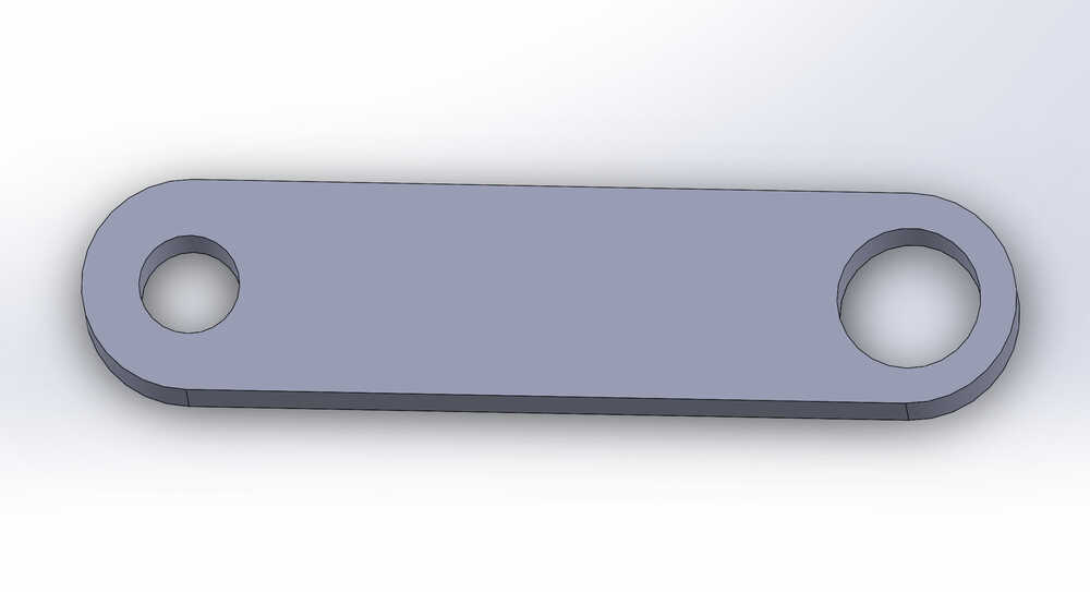
Arm 2
Top Plate
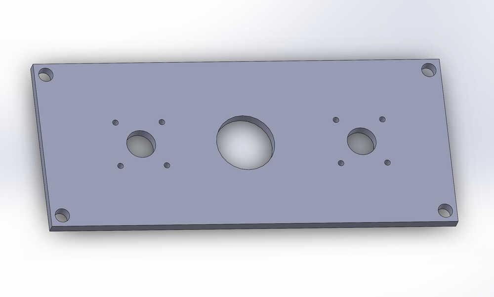
Top Plate
Bottom Plate
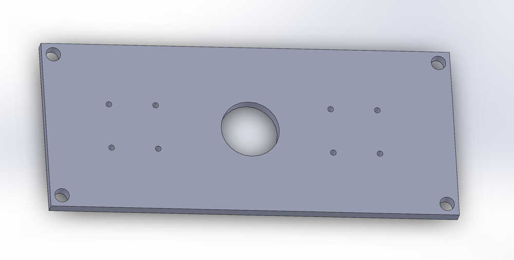
Bottom Plate
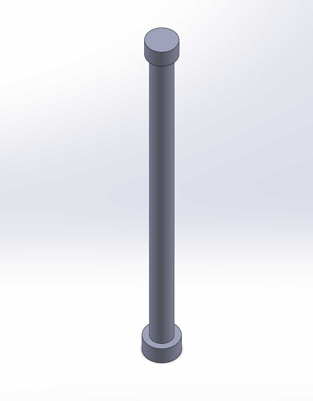
Central rod
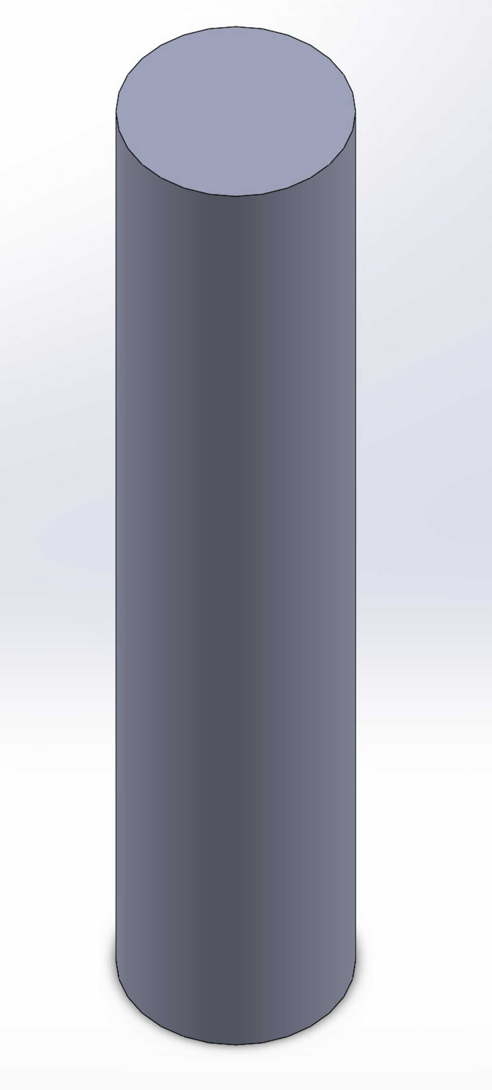
Central rod
Legs
A leg
Combined
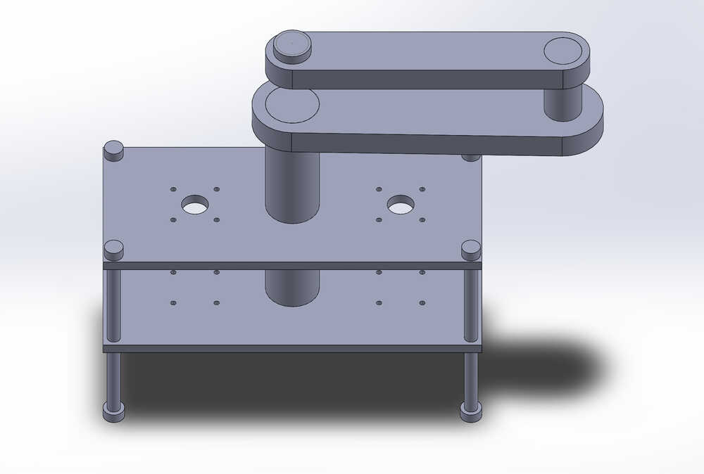
A view of the current CAD file assembled together, the arms spin
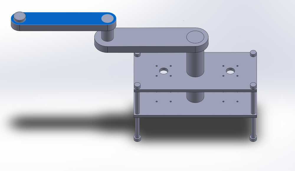
A different view of the assembled piece
Electronics
2 stepper motors linked to a micro controller on a circuit. The steppers have 4 (or 6) output wires for controlling the stepping. I am thinking of making my own software layer to control the spinning of the motors. To create the turning designs I am thinking of having a way of connecting to the machine with a wire to a laptop and appending to the list of known designs. The machine iterates through the known designs and creates them in order. Ideally there is a way to connect to the machine via Bluetooth or some other protocall howver that seems more advanced.
Materials List
- 2 stepper motors
- 1 8 pin micro controller
- top plate--cut from acrylic
- bottom plate--cut from acrylic
- Arm 1--3D printed
- Arm 2--3D printed
- 1 belt cut into 3 pieces
- 1 magnet
- 1 ball
- 1 central rod--3D printed
- 4 legs--3D printed
- Sand
- bearings
- bolts
- spacers
- nuts
Mechanical
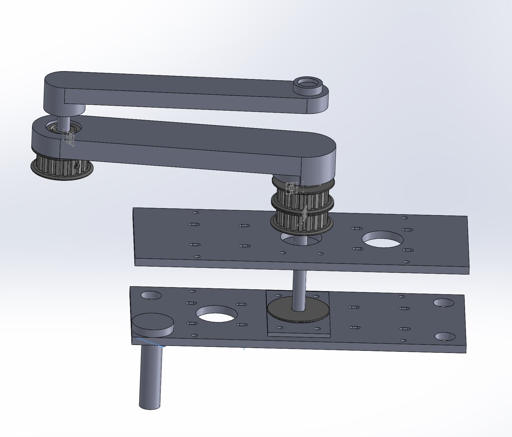
Final CAD design
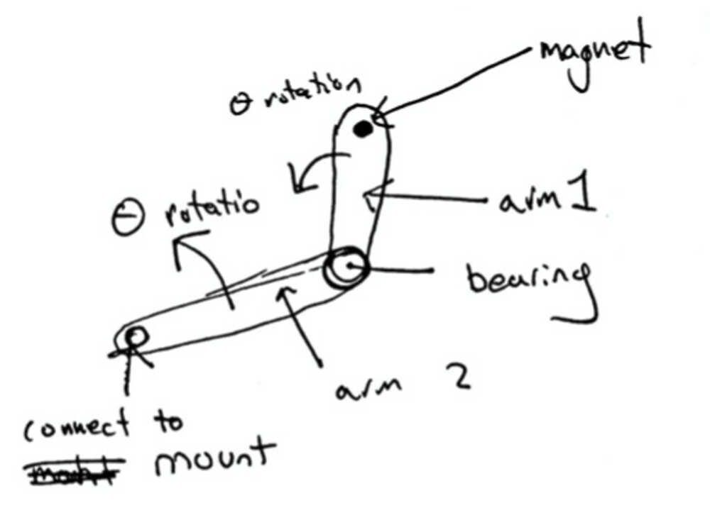
My final CAD design is below. There are multiple parts interacting. First is a central rod that will be guiding the stepper that is facing down. This rod will go through the center of the machine and connect to arm 1. The first arm is used to get theta rotation around the center of the machine. The second arm connects to the first with a second rod and is used for theta rotation around the end of arm 1. I am using gears and bearings to connect the different parts together.
For the body I am laser cutting the acrylic out for the connections. I have multiple mounts that are added on also to help hold the central rod.
The movement from the stepper comes from 3 XL belts that were bought on mcmaster along with pulleys and gears. The bottom stepper controls rotation of the central rod while the top controls the movement of arm 2.
Electronics
For the electroncis I am going with 2 stepper motors for the final. They have 4 wires coming out to control how they connect to the input device.
Board Design
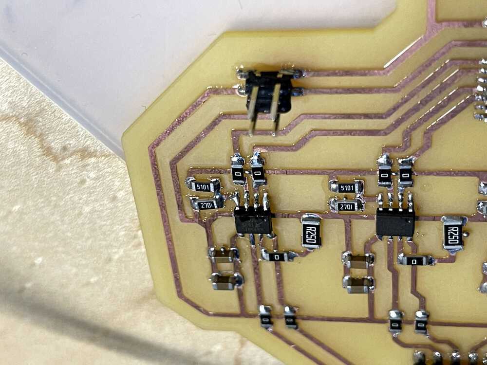
For the board design I made a board that uses 4 h bridges to connect to the attiny1614. They are connected with a 6 pin input and a 4 pin for the wall outlet plug. The output from the 8 out plugs is going to sit in a 10 pin connecter that will connect to my laptop. The wall power will come in from an outlet into a 9 volt supply that goes onto the board with 2 wires. This will be used to power the 2 steppers. Each of the 4 hbridges have 2 capacitors after them with 0.1 u and 10u to control the variance coming into/from the stepper.

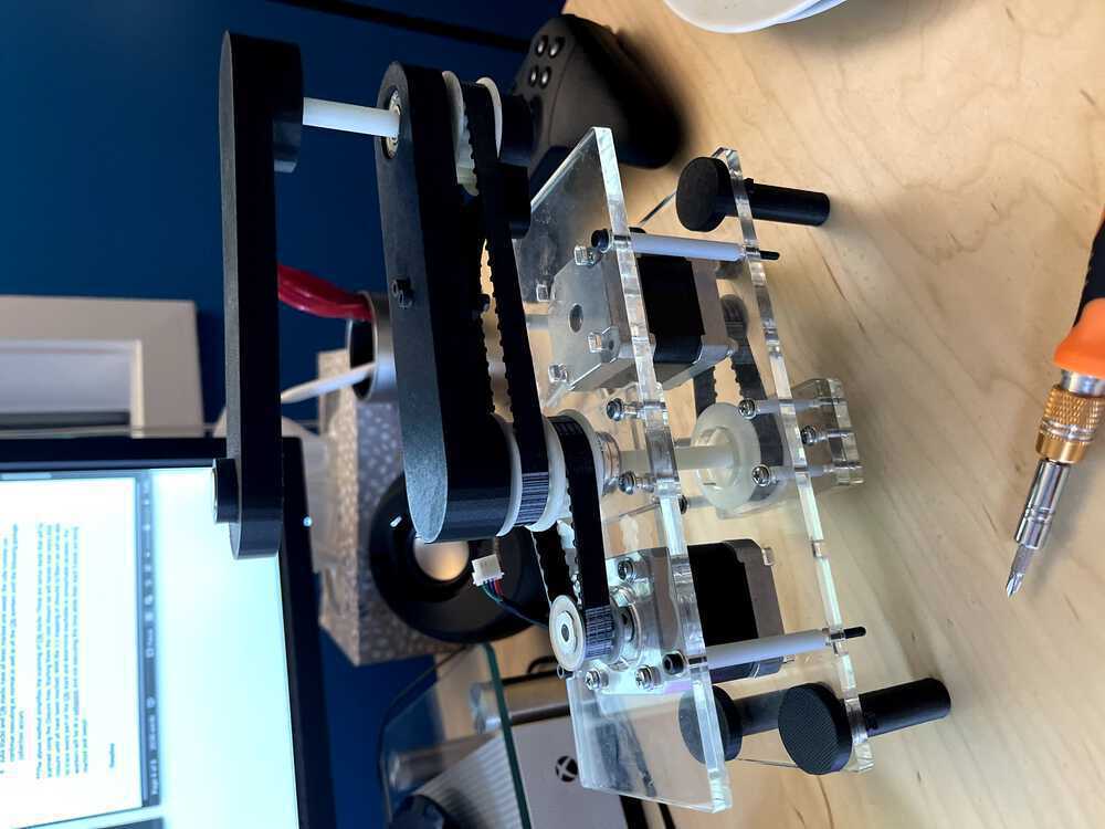
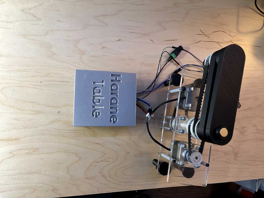
The CAD machine
Different view
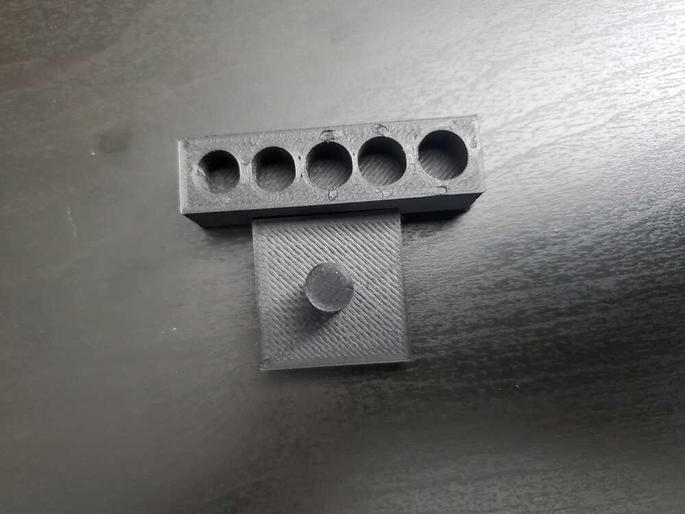
Testing the tolerance of the 3d printer
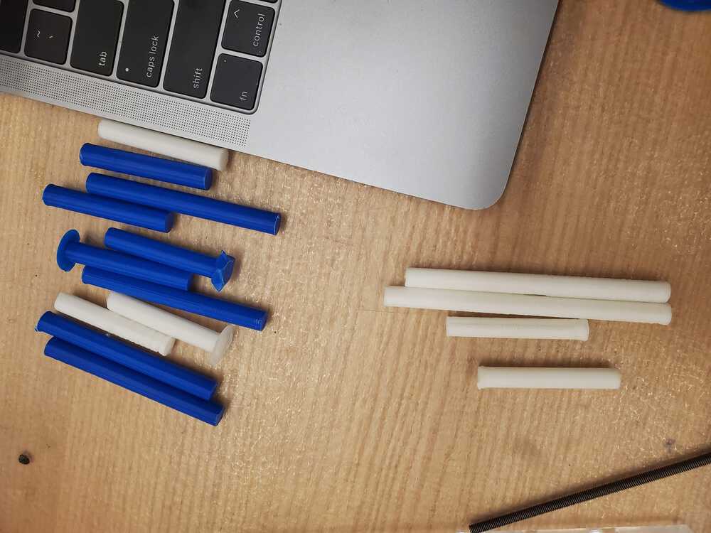
Many iterations of central rods
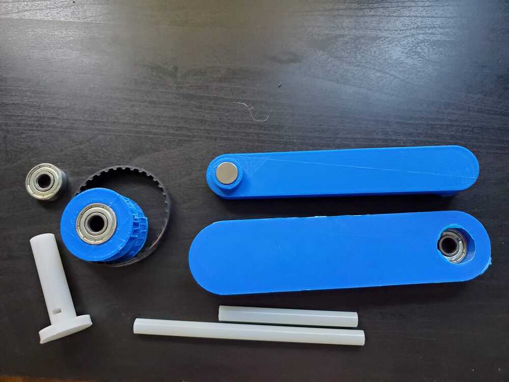
3d printed parts, some laser cut
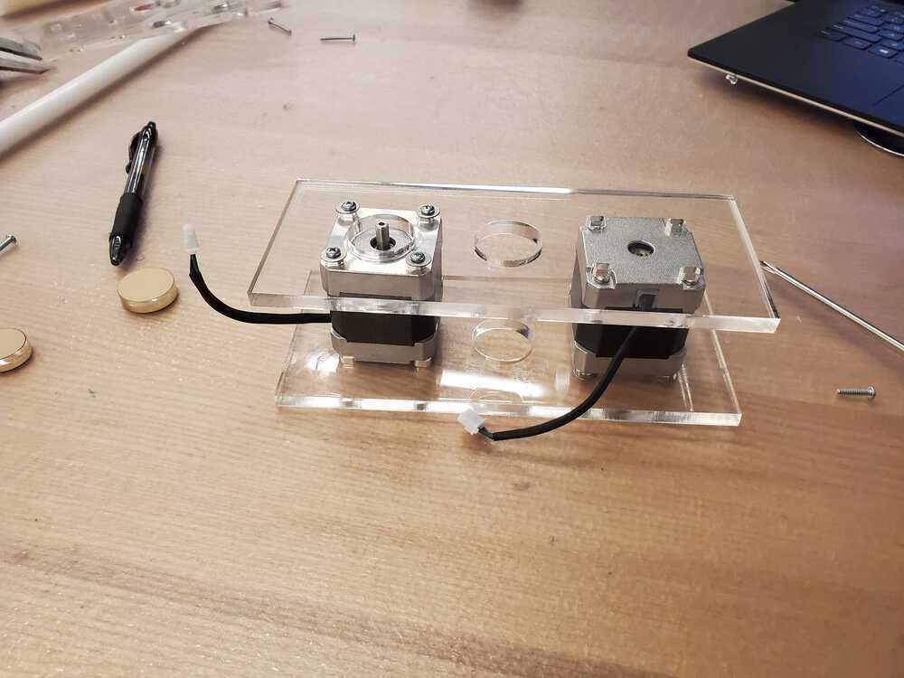
Steppers living on the acrylic
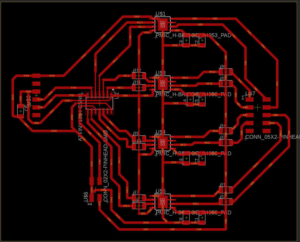
The board design
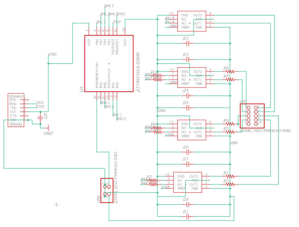
The board design
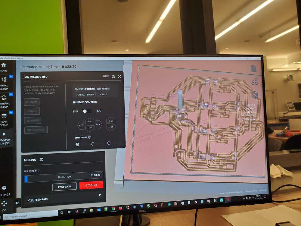
Cutting out the board
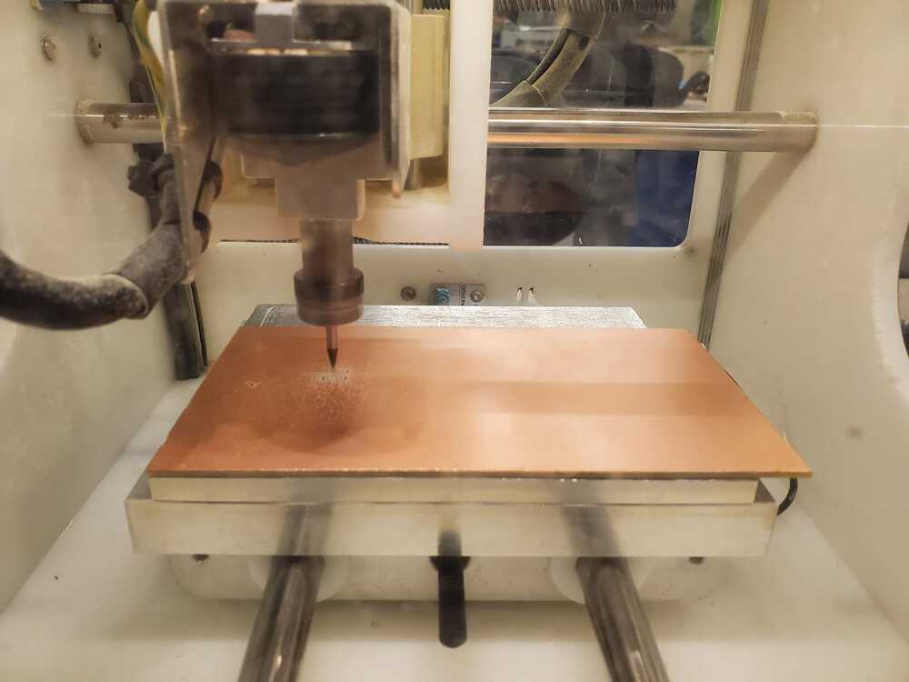
Cutting the board on the Othermill
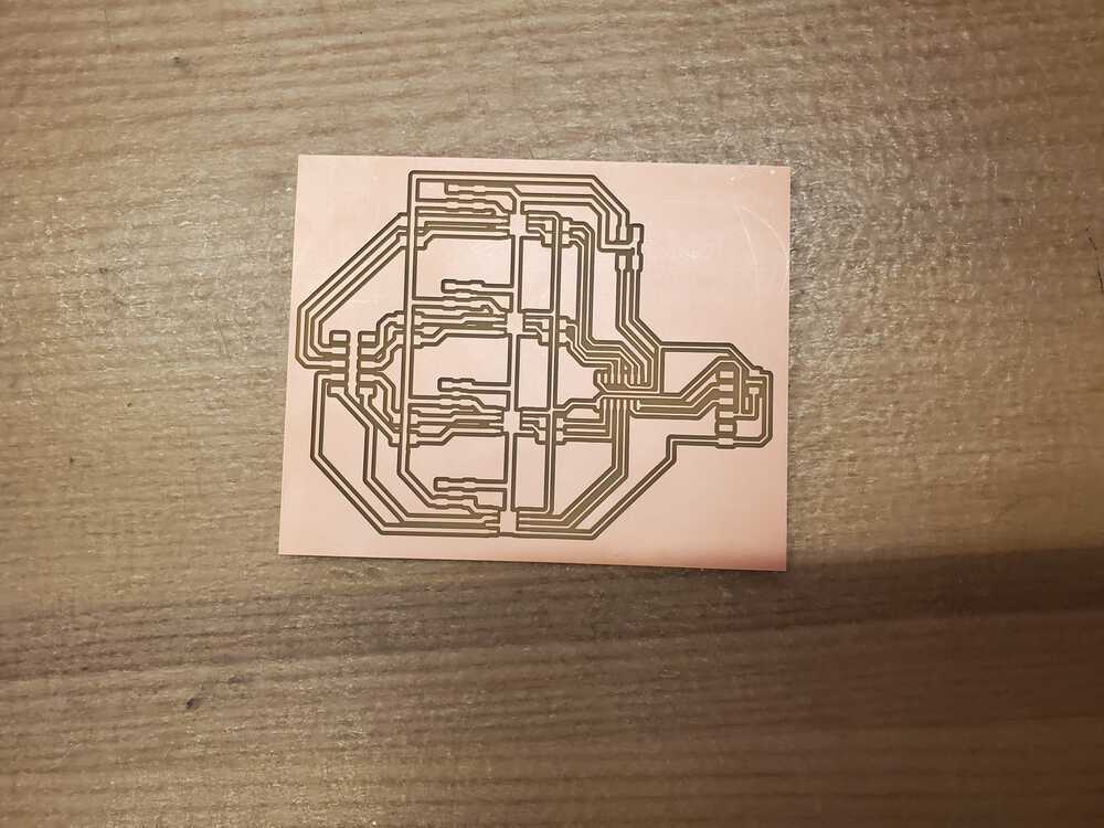
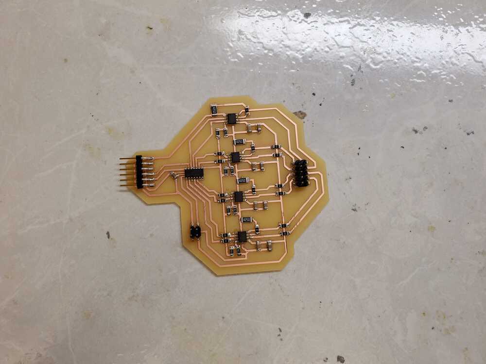
The cut out board
Final Electronics Design
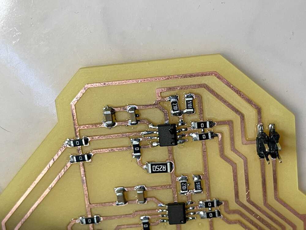
I finished off the project using the same board as above. The board has 4 h bridges, an attiny1614 and many resistors and capactiors. Each H bridge is powered by a central line of wall power coming in at 9 volts with a barrel plug converter from the wall. This is used to get gnd and wall power to the system. In addition, each h bridge is connected with 2 capactiors to reduce the variance in voltage going through the h bridge system. Each h bridge takes in 2 outputs from the 1614, gnd, vdd, and vbb. This is then converted into 2 outputs each that are fed into an 8 pin connecter at the end. These 8 pins are the wires going into the 2 steppers (4 per stepper).
I have far too many battle stories about the board to put on here but I'll list a couple notable ones: Anthony helping me with getting my first stepper to work after me not being able to get it to run for a couple of hours. We are running the pin combinations manually (with setting one pin to be high and the rest low in order to get the stepper to turn in the correct direction) and we find a configuration that starts to power the first stepper! However, using that same ordering into the arduino stepper library still gave no revolutions. Needless to say, I stuck with the manual approach instead of trying to figure out what Arduino created into a libary. Another notable story was trying to get the second stepper to work. I had 3 h bridges and the first stepper working perfectly at this point. They were all posting the correct volage when triggered by the 1614; however, I could not get h bridge 3 to work after probing everywhere and finding no shorts. The h bridge always seemed to show 9 volts instead of the 6.3 volts I was expecting from each h bridge output. I probed around the area of the power line (9V) to the outputs of h bridge 3 and finding no shorts there either. I go off on a whim and take off 2 0 ohm resistors that are crossing the power line with the outputs, clean up the area and re-solder them back on. I try again and the outputs work. I have no clue still how it was not picked up by the probing but I got my steppers turning finally :)
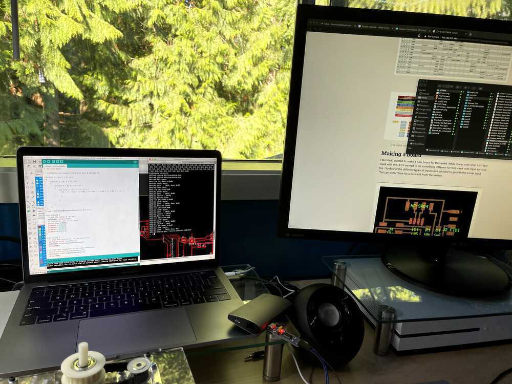
How to send issues to Anthony during remote
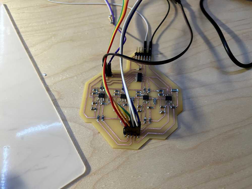
board
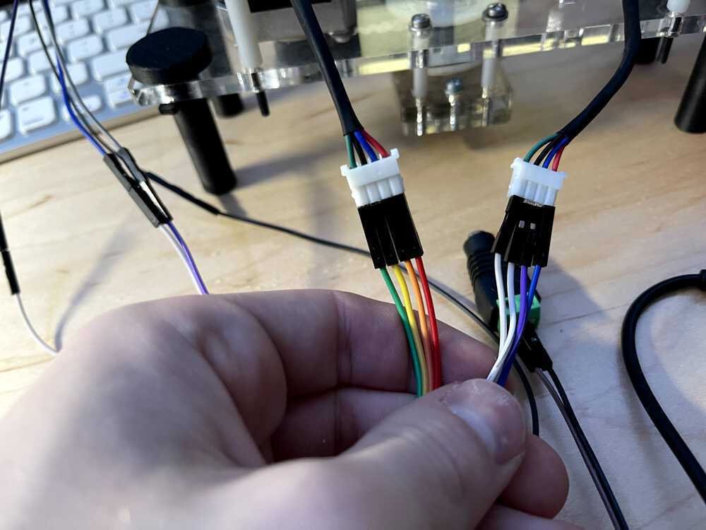
the wires into the output
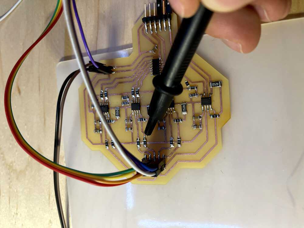
Probing for issues
debugging the board
Having issues with the board
Debugging
how steppers attached
The first time both motors spun
Software
For the software I wanted some way to control the steppers to make the shapes I wanted. In addition, I wanted a way to be able to have inputs go back into the laptop and be displayed as they were happening. Ideally this would be built into an app on a phone but we work with limited time here.
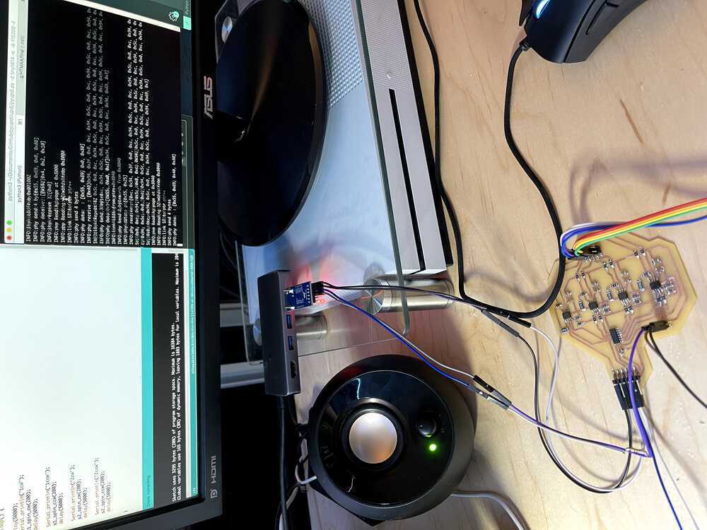
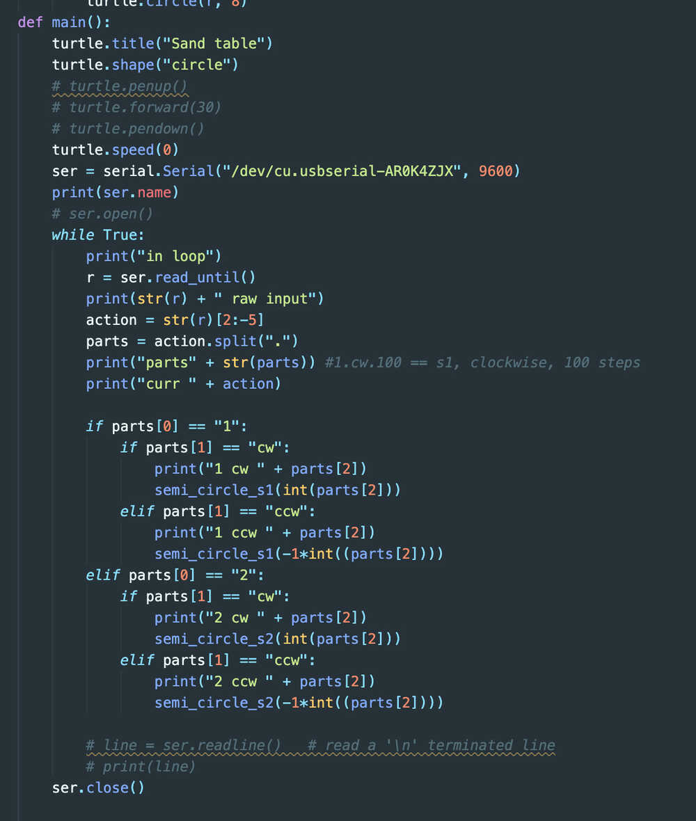
For the stepper code, I used the Arduino ATTiny1614 megacore library to program my microcontroller. I was able to write code, upload through updi and then run the code while being plugged in with wall power and the laptop programmer. This amounted to a slower development cycle than I had hoped (with switching wires back and forth between programming and testing) but was successful anyway. For the stepper file, I created multiple functions that would do the turning for me. For the first stepper, the correct pin ordering was 2-0-3-1. I originally had these spin with 0.002 seconds between each pulse; however, this was too fast so I switched this to be 0.004 seconds between each. I created functions to spin arm 1 for a certain amount of degrees clockwise, arm 1 counter clockwise, arm 2 clockwise, arm 2 counter clockwise, and then combinations to have them move at the same time in either cw or ccw directions. I also created some functions for microstepper the top arm to make a more smooth motion for the stepper and be able to handle 0.008 second waits between different pulses...it did not like this 100% of the time but was the current best solution for handling the slower movement from the steppers while remaining smooth. The way to flash the microcontroller is with: python3 ~/Documents/GitHub/pyupdi/updi/pyupdi.py -d tiny1614 -c /dev/cu.usbserial-AR0K4ZJX -b 115200 -f ~/Dropbox\ \(MIT\)/School/Meng/HTMAA/final/stepper_oneRevolution/stepper_oneRevolution.ino.t1614.20c0.u5V.mD0.hex -v
Now I moved onto the software for the vizualization side. I was able to (with a lot of Anthony's help) get the c code running on the microcontroller to post when it was doing certain movements from the functions mentioned above. It would cast this over serial and a python script of mine would be looking for said input. It could read this input and start to display it using a library called Turtle (https://docs.python.org/3/library/turtle.html). This tool was easy to pick up and did the basic display needed for this project. On a command start from the hardware, the software would also start to vizualize the same trace that is being made by the ball at the top of the arms. This started to come together really well in in the synchronization since I created the ball moving on the screen to match the speed of the arm movements. This should be ported to an app fairly easily at some point. I created functions for the machine to be able to do a looping circle. It creates a circle with the top arm and afterward moves the arm holding it by 5 degrees and repeats. This creates a lily pad-like pattern on the design. In addition, I created a spiral that spirals from the center out. This can be reversed and have the spiral work on the way in.
The code is attached
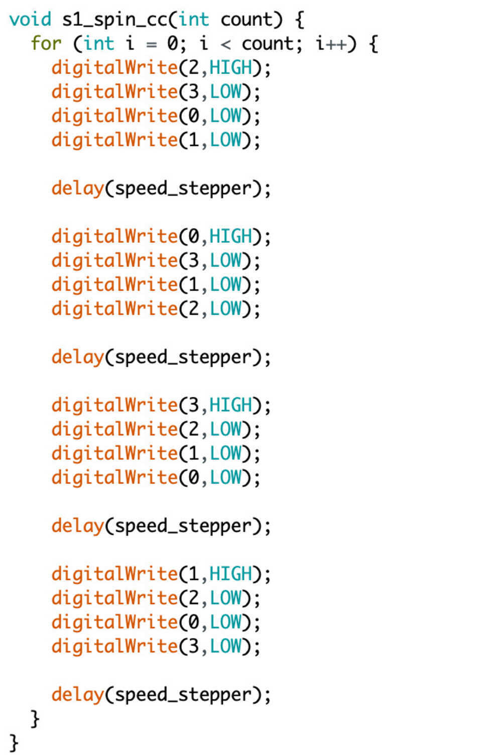
code for s1
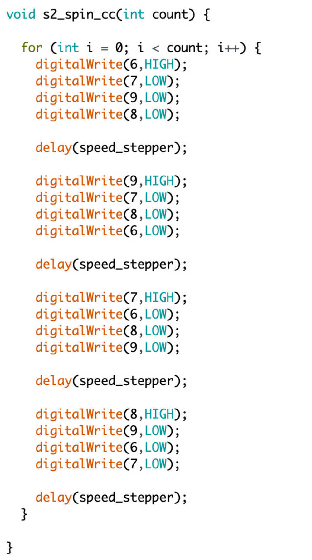
code for s2
Testing doing 360's with each arm
coding steppers
python code
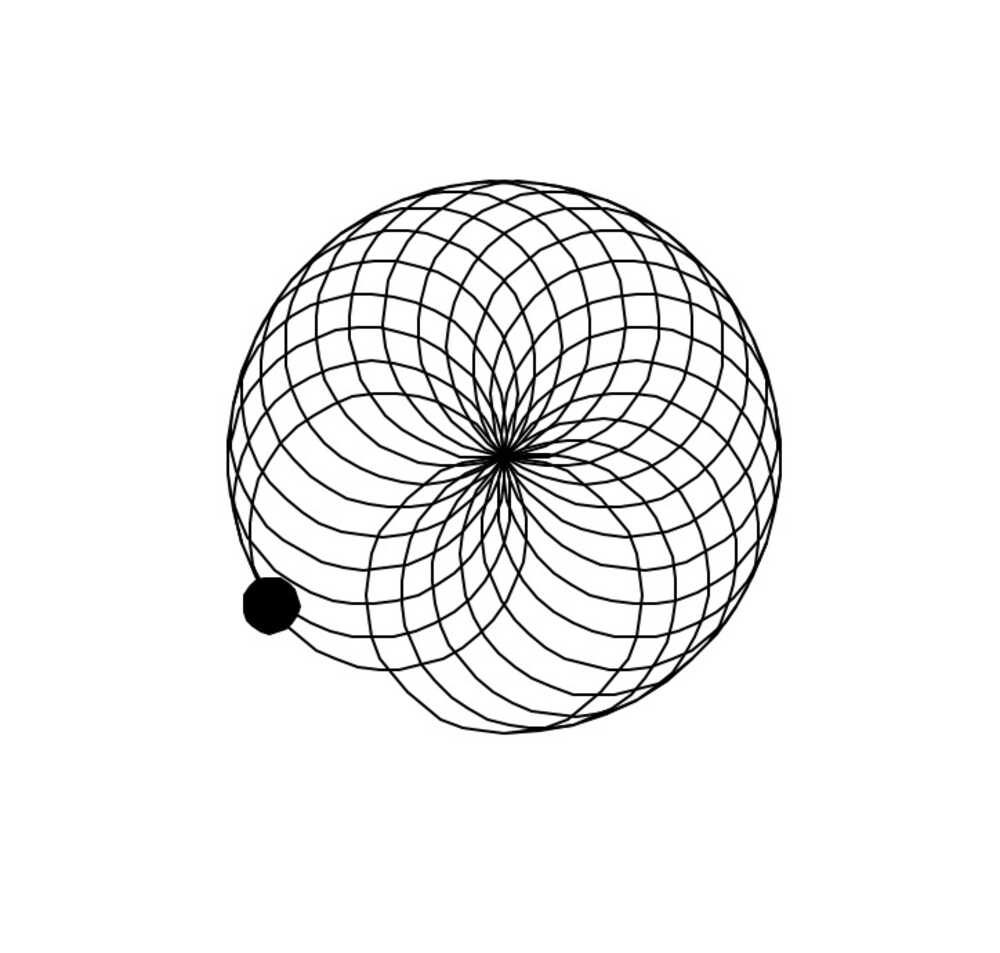
output of code
Final Hardware Design
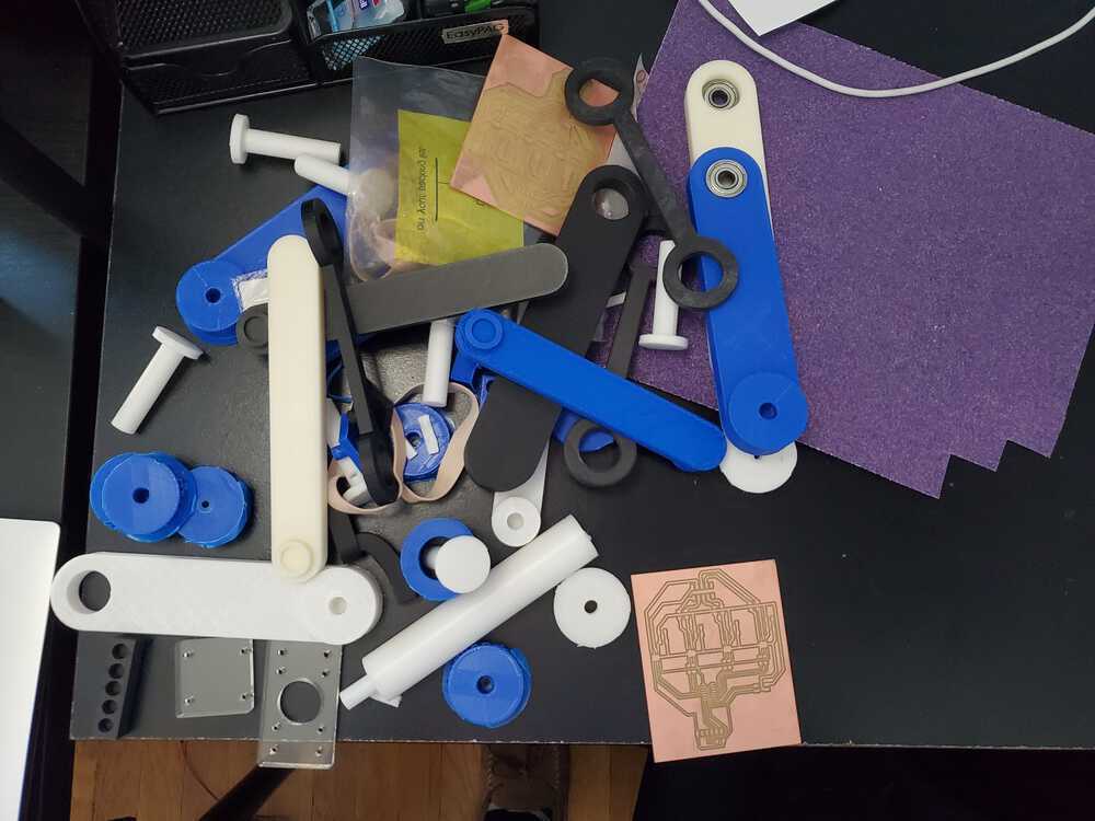
All the extra iteration parts
There are a lot of CAD files that I made to have this project come together. I think it may be best to list off the different parts and then talk about the more important ones. I hope that most of them can speak for themselves as to why they are useful or important to the design.
Acrylic Base
The main part of the structure is the acrylic base plates. There are 2 that look very similar for the top and the bottom. Each of these hold 1 stepper in place. The bottom one also has holes for the legs. These two are linked together with 4 very large screws along with nylon spacers to give the machine some structure. They are held together with nuts at the end that are tightly fastened to compensate for the steppers spinning a lot.
Rod and Arm Connection
There is a central rod that marks the middle of the machine. The rod is there to provide the stepper that is facing down a part to turn the bottom arm. The rod is held in place with another acrylic combination of 2 acrylic blocks that are combined to hold a bearing in the middle of the top one and the bottom as a brace for the rod/bearing. This allows the rod to spin freely with minimal friction coming down at it. These two connected acrlic peices are also using nylon braces to hold them tightly in place and not allow the rod to move very much.
The central rod has 2 different types of gears on it. The bottom gear is one that connects to the stepper facing down with a belt. The belt is 7 inches long and is tightened manually with the stepper screws. The stepper in the acrlyic has elongated screw holes to allow one to connect the pulleys and gears and then add resistance and screw them in place. This creates the tension needed to allow the pulleys to be tight. The other set of gears on the central rod connects to the second stepper motor with a 2nd pulley. This is a double gear combined as one piece and a larger center to allow bearings to fit inside. The bearings allow the 2nd stepper to rotate independently from the first and turn the 2nd arm.
The two arms move independently from each other powered by 2 steppers. The two arms together allow the end of arm 2 to reach anywhere in a set of points 2*r away from the central rod location.
Electronics Enclosure
I created an enclsure for my electronics board and some wiring. This is a simple case with a top and a bottom that hold together with press fit ends at each corner that was 3D printed on a Prusa. It is fairly minimalistic and covers the board well to hide the ugly parts of it from view along with protecting the pieces. The box is fit really tight however can be opened with some work and a screwdriver to wedge it open without breaking it.
The final look!
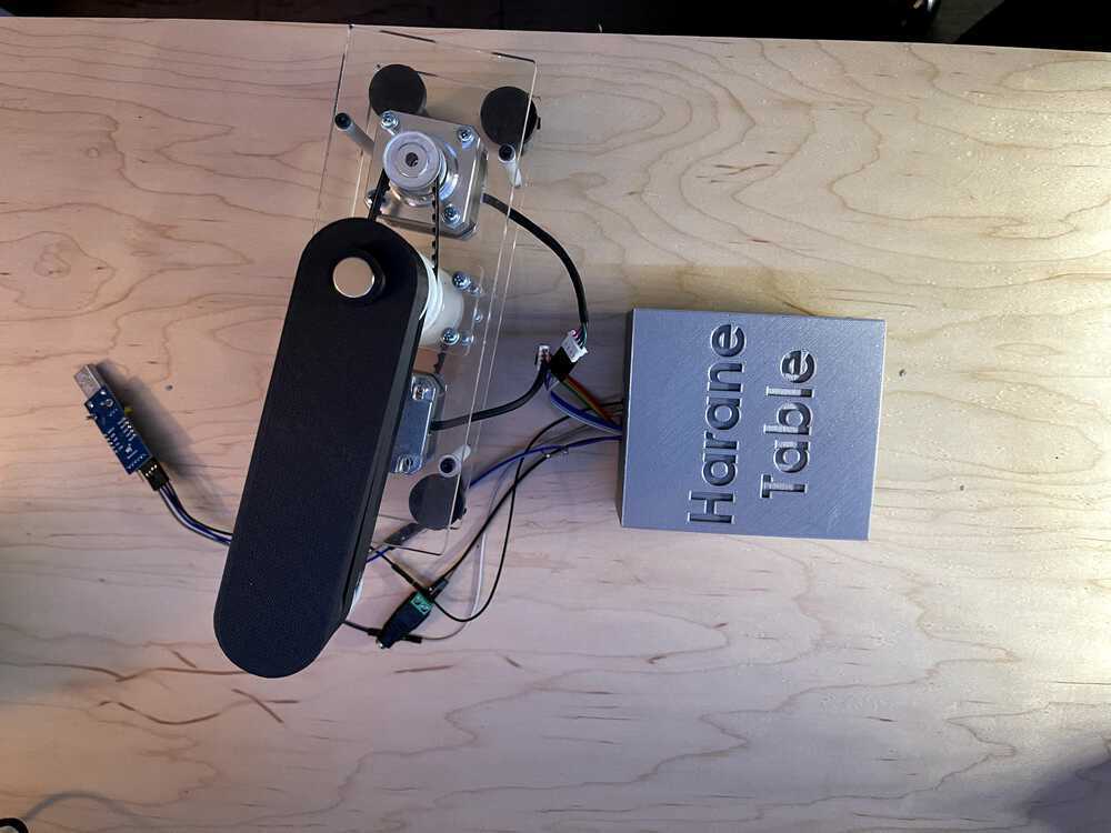
The final look
The final look, different angle
A showing of the completed project!
Future Improvments
Below are some improvements for the future of this project
Electronics
The first piece to improve would be to add a regulator to the board and enable it to run without tx, rx, vcc, and gnd from the laptop. The regulator would take in the 9v wall power and output 5v for the microcontroller input by connecting with a 3 pin connecting to gnd, vdd, and creating a new vcc for the microcontroller. The only change would be this 3 pin and an extra 0 ohm resistor to jump 1 trace.
The second major imporvement would be to remove the necesity to plug in to the board at all. I would want to connect the board to wifi to control it. I think this would be a little more complicated than bluetooth but add a lot of ease of use to the overall structure. It would function similar to how a Google home would function with connecting to it. I think I would use an ESP32 to power the chip instead of the attiny1614 since it has wifi built in.
App
An app on the phone that through wifi can show you the vizual software would be a nice touch. Also control of LEDs and other accessories such as inputing your own designs.
Steppers
The current 4 pin steppers I am using are built for fast movement and do not preform very well at slower movement with how they are being operated on in my design at the moment. I would explore other options such as different steppers or making gears more atune with bikes that decrease the amount of final turn from the stepper turning (ie letting it run at 2x speed for the same amount of rotation).
Thank yous
I think Anthony should honestly get a whole page to himself for the help her provided me in this project. There would be absolutely no way I would have gotten anywhere on this beast of a mechE project as a cs major without him. Thank you very much for the long lab hours and long Zoom calls when we went remote. In addition, I would like to thank the course staff for being so helpful in general and setting up a great class--it was fantastic even during COVID times. Thank you Neil for teaching and running the class, Jake for the Clank, and Premila for the TAing in lab specifically.