Product Description
What does it do?
This is a machine that can flip pages of a book in both directions. It’s a real page-turner ;)
Who's done what beforehand?
I was not able to find any similar projects in the fab academy. I did find other projects on the internet that I took inspiration from. In particular I want to give credit to this publication that described the mechanism design I tried to replicate.
What did you design?
I designed all of the hardware, electronics, and software. Specifically, I designed my own dev PCB board using the SAMD21E18 micro controller, PCB servo hub for organizing servo controls, acrylic table and book platform, acrylic arrms, wheel, and all embedded software.
Materials and Components:

What parts and systems were made?
The table top, base platform, servo arms, and servo wheel were all laser cut. The brackets to fasten the servos to the table tops were 3D printed. The PCB boards were milled and stuffed. The embedded software was implemented in Arduino and Node JS.
What processes were used?
All hardware parts were designed in Fusion 360. For those parts that were laser cut, they were exported as DXF's and imported into Rhino. The 3D printed parts were exported as STL meshes and imported into Sindoh software. For fabrication, I used the Epilog laser cutter, Sindoh 3D printer, and Roland SRM 20 for milling PCB boards. Lastly, I used soldering to stuff my PCB boards.
What questions were answered?
My main questions while designing this machine were: 1. Will the servo's I selected have enough torque to hold up the servo+arm+wheel? 2. Will the wheel be "grippy" enough to drag a page? 3. Will the wheel only grab 1 page and not multiple?
What worked? What didn't?
80%-90% of the time it successfully turns a page! It performs best on pages without any folds in it so that it can be rounded wheel and the bottom arm can successfully get underneath it. It works best on hard cover books, but does not work that well on paper backs because the pages can’t be pined down. Sometimes it does rip the page...
How was it evaluated?
I measured success for this project by the following critera: 1. Does it successfully turn a page a majority of the time (in both directions)? 2. Is it easy and intuitive to command? 3. Does it adapt well to different book sizes?
What are the implications?
This machine could be extremely useful for disabled individuals who don’t have the dexterity to grip individual pages with their hands.
3D Modeling in Fusion 360
Here's a timelapse of my entire CAD assembly. I designed all of the subcomponents in different files and integrated them all into one design.
And here are all of the parameters I defined:

Initial Base Platform
The base platform is the platform on which the book will be layed. It is also the place where all the servo motors will be mounted and electronics integrated. I also wanted to be able to change the angle of the platform. To start, I leveraged my design from the make something big week:
If you look closely, I added mounted holes all around the table top for servos. Unfortunately, this design turned out not to be stable - more on this in the fabrication section.


More Stable Platform
I really liked the table top, but I needed a more stable and robust base. I decided to redesign the base, this time using finger joints for more stability:


You'll notice that I have 6 legs and 5 cross braces. This is excessive, and I did this intentionally. My plan was to fabricate more pieces than I needed, and during the assembly phase I would test out how many legs and braces I actually needed; I ended up only needing 4 legs and 2 braces.
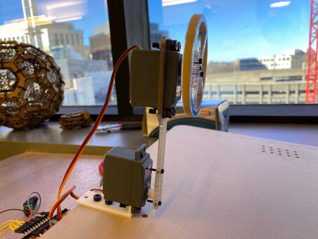
Servo Brackets
To attach the servo's to the table top, I needed to design some brackets. Specicially, I need one bracket that will hold the servo up right, and 1 bracket that will hold it horizontal. I found this super usefuly CAD model of the HK15138 servo, so I was able to design my brackets to be compatible precisely.


Since these brackets can't be fully projected onto a 2D surface, I needed to 3D print these. I exported these as STL's and printed them on a Sindoh 3D printer - more on this below.
Servo Arms
I needed to design several arms to attach to the servo, and an arm that will also hold a servo (the one that controls the wheel).
The arm on the left is for the bottom servo arm that does the actual page flipping. The one on the right is for the side servo's that help pin the page down.

And here is the top arm that will be attached to the top servo, and it will also hold up the servo that controls the wheel.


Servo Wheel
I needed a wheel to rotate and drag a page. Since this wheel will be attached to a arm with a servo, and it's being held up by another servo, I needed it to be light weight.


I experimened with different wheel diameters. I 3D printed one at 2.5in, but that turned out to be too small. It also took quite a while to print, so I decided to turn to 1/4" acrylic and laser cut a wheel. I laser cut three at 2.75in, 3in, and 3.25in diameters. I ended up going with the 2.75in diameter wheel (pics below).
2D Projections for Laser Cutting
Here are all the 2D projects I made to laser cut. These are screen shots of dxf files (linked below) that I imported into Rhino.


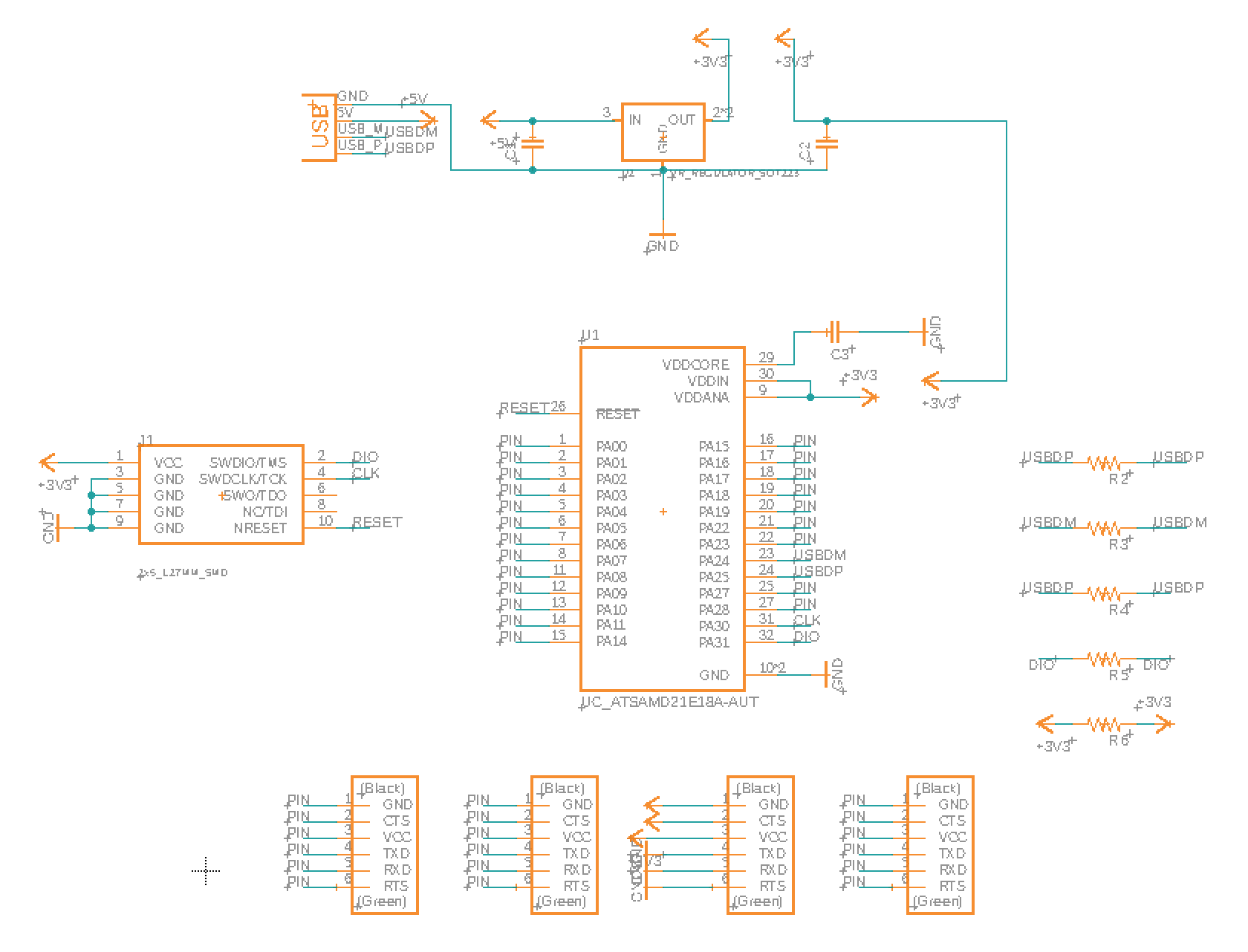
Electronics Design in Eagle
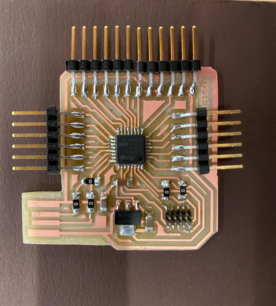
For my electronics, I made use of the D21E dev board I made during input device week, and the servo hub I designed during output device week. These two PCB boards were all I needed. I was able to control my servos and take in inputs via Serial, buttons, and step response (more on this below). Here are the schematics and board designs:


Fabrication
Laser Cutting
Before going straight to acrylic, I wanted to test out my design on cardboard. I'm glad I did, because I discovered that my initial design is not stable enough:

From here I redesigned the base to be lower to the ground, have more support, and use finger joints. I was confident that this design would be more stable, so I proceeded to laser cut it into the acrylic sheet. This is what it looked like assembled:

I also laser cut the wheel. I cut three different sizes since I wasn't sure which one would work best.
PCB Milling and Stuffing
I milled both PCB boards using the Roland SRM 20 in the arch shop. Please refer to my previous weeks for a more detailed description of my milling process. Here is what the final boards looked like after being milled and stuffed:

3D Printing
I 3D printed my servo brackets on a Sindoh 3DWOX1 (I also 3D printed a 2.5in diameter wheel but unfortunately I don't have a pic of it). They turned out super well:

Assembly
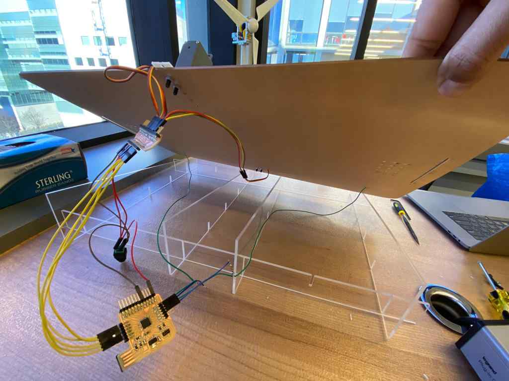
Base
I started by assembling the acrylic base. While the finger joints made the structure stable, they were quite difficult to fully push in due to tight tolerance. In the future I would like to add a tad more tolerance.

Mounting Servo Brackets and Arms
To mount the brackets and arms, I made use of the following fasteners:

And I then fastened the servos to brackets and brackets to the table top. And then I connected the arms to the servo horns that are held in by the screws provided with the servo. For the wheel, to make it grippy, I simply put a rubber band around it, and this worked remarkably well!


Connecting the Electronics
For the electronics, all I had to do was hook up my servos to my servo hub, and connect the corresponding signal wires from from the servo hub to the digital pins on my dev board. I also connected power and ground from my external power source to both the servo hub and dev board.


Testing the Mechanism
Now that all the servos were mounted and electronics connected, next step was to test out the mechanism. Eventually I need all the servo's working in unison, but to start I wanted to move each servo individually to test if 1. the wheel would be able to grip a page, and 2. if the bottom arm would be able to flip the page to the other side. Much to my surprise, it pretty much worked on the first try! Here's a clip of me controlling the servo's manually. To do this, I used the servo_control.js script I made during interface and application programing week. This script communicates with my dev board over serial.
Coordinating the Servos
Now that I was confident the mechanism was working manually, the next step is to program the movements of the servos so they move in unison automatically. Please have a look at my code file below for a detailed description of the algorithm. At a high level, the states of the servos can be categorized into two positions: Base Position, and Page Turn Position.
Base position is when the servos are in their rest state, waiting to be commanded to turn. Specifically, the degrees are:
- Top Arm: ~25 degrees
- Wheel: 0 degrees
- Bottom Arm: 0 degrees
Page Turn Position is when the servos are trying to turn the page. I command the servos to move to certain degrees, but equally as important is the order in which the movements happen. This is roughly the steps:
- Rotate wheel to 180 degrees (this grips the page and pulls it up)
- Rotate bottom arm to 180 degrees (this hooks onto the lifted page and drags it to the other side)
- Rotate top arm to 30 degrees (this lifts the top arm up slightly so that as the bottom arm turns the page isn't pinned by the wheel and the page won't rip).
Note that the degrees above are for turning the page from right to left. To turn the page in the opposoite direction, I simply subtract the above degrees from 180 since it is symmetric.
An interesting thing I discovered/realized as I was turning the pages is that as you turn pages in one direction, say right to left, the thickness of the book on the right side is decreasing and the thickness on the left side is increasing. To account for this, I keep track of how many pages have been turned in both directions, and I update the angle of the top arm accordingly. For every 4 pages turned, I decrease the angle of the top arm by 4 degrees so that the wheel will always maintain sufficient contact with the page.
Here's a clip of all the servos working together:
Adding Touch Controls
The mechanism is now working great! But I was having to control it with left/right button clicks which I didn't think was very convenient. Since I had an extra 2 days before the final presentation, I decided to try and see if I could make two capacitive touch pads using step response!
The setup was actually quite straightforward. I need 1 transmit pin and 1 receive pin. On the transmit pin I am sending out a square wave. It is connected in series with a 910K resistor, and on the other end of the resistor is a wire connected to the receive pin, and a wire connected to copper tape, like so:

Essentially, when I touch down on the copper tape, is acts a capacitor and takes time to charge. This introduces a phase shift in the square wave, and this can be measured on the receive pin. I basically wait to see if there is more than 10% change in the "un-touched" reading on the receive pin to detect a touch, and if so, I initialze the page turn sequence. Here's a brief demo:
Lastly, I wanted to make the touch sensors look nicer so I cut them and pasted them on the bottom corners of the patform:


Final Presentation
It's show time. I arrived to the MIT Media Lab 6th floor in the morning to setup:
I'm pleased to say the presentation went well! The mechanism (mostly) worked, and people enjoyed it working it action. Here are a few clips:
Files
page_turner.ino (Arduino sketch that has all input and output controls)final_cad_files.zip (Contains base, table top, top arm, bottom arm, and wheel)