My jellies tell me I'm gonna face many problems with
creating a ciruit board for my final project.
"Fail early to suceed sooner!" is the thought I had with
the previous electonics week.
Turns out, I did run into a bunch of problems trying to
make my first prototype work software-wise.
The board from last week
@Archshops - Connection Troubles
For one, the board would not be recognized by the
computer's when plugged into its USB port. I wondered if the board
got messed up or if my computer was faulty.
Unfortunately, it would only connect to me computer
through a USB extension cable, which I did
not own at home. Luckily
there was one at the ArchShop, but I didn't want to
hog the single computer and extenion cable there.
Calvin suggested it may be because some boards work
better over USB2.0 rather than USB3.0.
Afterwards, what was confusing was that I was certain I
was able to upload and run Neil's echo.ino
code for the ESP32 before, but when I tried again this week,
I could no longer upload any other sketch using even
the Archshops computer, which worked before.
When I tried at home, I was so worried it was a board issue. But now it's recognized as being attached!
FATAL ERROR. What used to work doesn't
@EDS - MY PROGRRAMMER thinks its an ESP32 and tries to fool me
I stopped by EDS to try again. Maybe Anthony would have
another idea. He also lent me a USB extension cable
which worked.
At one point, Anthony made an off-hand
comment about the switch that connects GPIO0 to
ground (which I didn't truly parse what it did
until then), I
realized I've been misssing the 'loading ritual' or
setting the switch in the correct position
(which I marked on the back)
then pushing the button before every upload.
After a bunch of the same error and exhausting my
Google Search options, I went to Anthony, who removed
the ESP32, connected 2 pins on the programmer, and
found it was emulating the ESP echo program, saying
it's the ESP while echoing back what I typed into the
serial monitor. WHAT? WHAT! I guess I wrote the
program into the programmer instead of the ESP!
Another important thing Anthoony brought up is my
5 to 3.3V regulator was too small current-wise to do
things like wifi and bluetooth for the ESP. Also
that maybe the ESP32 doesnt take the normal neopixel
libraries I use. go figure.
USB! I got a USB cord from Anthony over at EECS, and I was able to work not-in-the-archshop-hoarding-the-USB-connector
Anthony reccomended to use a FTDI cable to bypass the
need for a programmer to convert USB data (which
is what the computer/Arduino coding writes in) to
serial (which is what the ESP32 takes in). It worked fine.
And is not trying to trick me.
FTDI! Thankfully, I could bypass the programmer board with an FTDI cord from Anthony.
The computer can program to the ESP (via FTDI)!
Comes out jank, but the ESP32 (and ACTUALLY the ESP32) can somewhat echo!
@East Campus - Probing for Problems
Showing and complaining about my board to a friend
on hall, they offered to help with the EE tools they
had in their room. It was literally a mini EE lab!
Gosh, the
things kids are into these days.
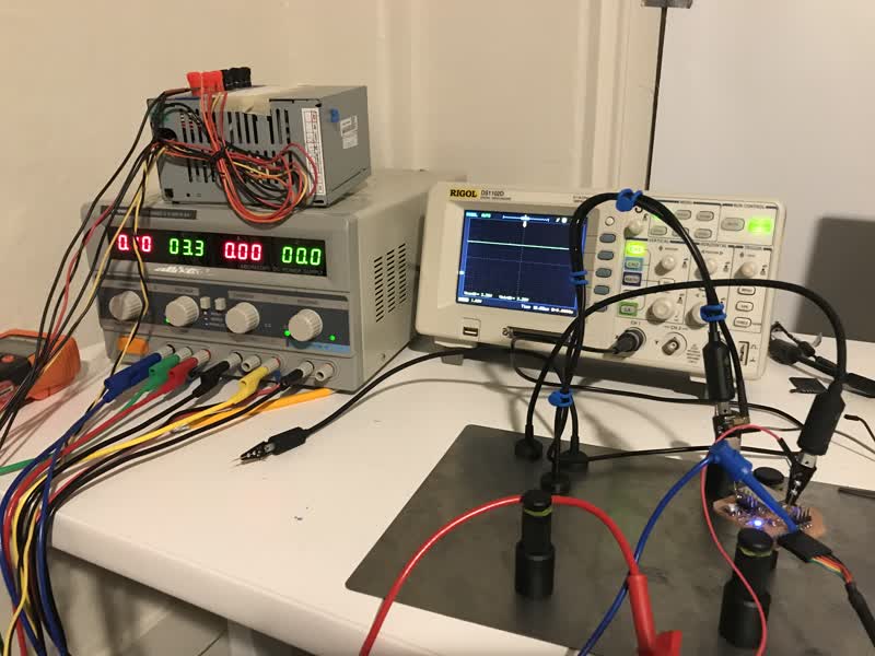
Checking the circuit with these super cool probes that hold in place
Voltage looks alright
Wait. Voltage is not alright. Trying to run
code to use wifi.
Voltage Regulator Fail
The above video shows a drop in voltage, which we watched
at the same time as the serial moniter. We had print
statements in the arduino code we tried to upload,
and the timing of the voltage drop to what was on
the serial monitor provided evidence that
program dies after trying to use wifi and doesn't
recover.
I used the hot air gun to reflow the
voltage converter and plucked it off with
a pair of tweezers. We then supplied our own voltage
using a power supply (a steady 3.3V),
and then the example bluetooth program goes through!
It was super neat to see a true hobbyist's dorm setup of
an EE lab and see what techniques and train of thought
they used to debug hardware.
Also, the probes were unlike anything I've used before!
Feeding it 3.3V
Wifi doesn't find anything, but program runs all the way through!
Does Bluetooth things!
LED attempt & fail
Turns out the data also needs to be 5V, not just
power to the LED. The video shows the signal is
outputting, but it's not strong enough to be
recognized properly.
UPDATE: The data line does not have to be 5V,
as I have found out through my final project. However,
with that potential reasoning gone, I do not know
what went wrong here. And for some reason all my
attempts and creating a logic converter to step up the
3.3V output from the ESP32 to 5V fail to work. :(
UPDATE 2: According to another EE friend of mine,
Winnie, the mosfet might not be switch on/off fast
enough to pass the signal to the LEDs. I did not think
the mosfet would be the limiting factor!
LED is supposes to be blinking red. Instead it's green?
@Mental Notes - Things to fix
New board needs bigger 3.3V converter - more current
--Anthony
Things needing >5V need bidirectional voltage converter (unsure if I'll need this)
--https://www.electroniclinic.com/learn-esp32-completely-esp32-course-for-beginners/
Tiny accelerometer look at useable pinouts
--https://www.youtube.com/watch?v=LY-1DHTxRAk
Grounds need to be connected?
LED Signal converter to 5V - logic converter?
MY PROGRAMMER BOARD :(
-- documented in week 8 (even though it was done closer to week 9-10ish)