Week 8 - Input Devices
— weekly — 2 min read
Input devices week is a great opportunity to work on final project related stuff! I already know that I am going to be estimating the position of the Pong controller based on the distance of the object from the edge of my Pong table. So I decided to experiment with the VL53L1X laser ToF distance sensor.
ATTiny Serial Board
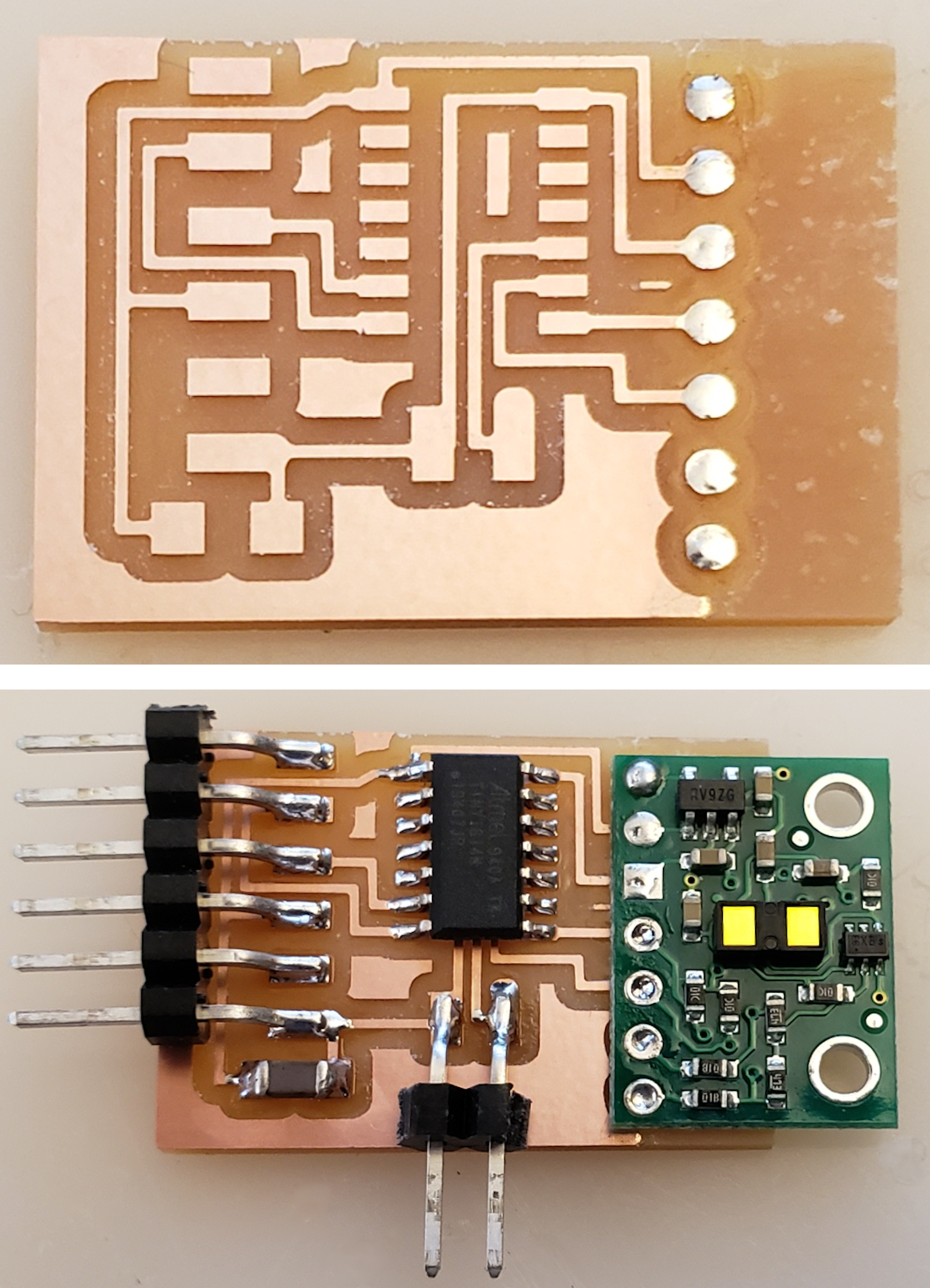
As a first step in the uknown world of input devices, and as a lesson from past weeks, I wanted to get something simple to work first and then iterate throughout the week. I decided to replicate Neil's ATTiny Serial board and connect it to the board I designed in week 2.

This is an extremely simple board to mill and solder, so as expected this came out nicely without any extra effort.

At this point the only missing thing was the VL53L1X module, which we ran out of. We were supposed to get them by Monday or Tuesday, so I thought of using this time to create a breakout board with SAMD21E18, this way when the module arrives I can simply connect it with a generic header. I should be able to use this board in my final project and in the following weeks.
SAMD21 Breakout Board
This is going to be quite a complex board to design. I followed Jake's phenomenal micro-controller guide to come up with the schematic of a generic SAMD21 board. The purpose of this board is to be able to connect anything easily in the future, including the VL53L1X when it arrives on Tuesday.


It took a while but I am very happy with my design. Time to mill!

As you can see in the above image, after 45 minutes of milling, it turns out that the SAMD21 legs were too close to each other on the KiCAD footprint. This resulted in all the pins coming out of the micro controller being connected to each other. Very bad. After discussing with Zach, the simplest solution for this was actually changing the footprint for the SAMD21 in the fab library. We edited all the traces to be a little more narrow and retried to mill.

This one came out beautifully! Time to solder my components.

Not the cleanest solder I've seen, but I thoroughly checked all the connections and they seem to continously flow current. This design was the first time I have ever used vias. All my grounds are connected together on the back of the board. The cleanest way to connect them is using rivets. This was a very satisfying procedure, using the rivets I was able to flawlessly connect all the vias.

Now I used the Atmel ICE to program this board. I wanted the board to have the Arduino MattairTech pin mapping, so I downloaded the corresponding binary and used edbg to program.


Now that my board is detected and programmed via USB, I can use it to connect the sensor. Tuesday has finally come and the modules arrived! I was excited to test them on my freshly created breakout board. There still was a little non-trivial soldering work to do with the connection header. I used a "third hand" tool to hold my board while I soldered the header to it.

Finally I can now connect this module to my breakout board!

And it worked! I used the library's example code to verify that the sensor reports the desired numbers
1VL53L1X sensor;2
3void setup()4{5 Serial.begin(115200);6 Wire.begin();7 Wire.setClock(400000); // use 400 kHz I2C8
9 sensor.setTimeout(500);10 if (!sensor.init())11 {12 Serial.println("Failed to detect and initialize sensor!");13 while (1);14 }15 16 // Use long distance mode and allow up to 50000 us (50 ms) for a measurement.17 // You can change these settings to adjust the performance of the sensor, but18 // the minimum timing budget is 20 ms for short distance mode and 33 ms for19 // medium and long distance modes. See the VL53L1X datasheet for more20 // information on range and timing limits.21 sensor.setDistanceMode(VL53L1X::Long);22 sensor.setMeasurementTimingBudget(50000);23
24 // Start continuous readings at a rate of one measurement every 50 ms (the25 // inter-measurement period). This period should be at least as long as the26 // timing budget.27 sensor.startContinuous(50);28}29
30void loop()31{32 Serial.print(sensor.read());33 if (sensor.timeoutOccurred()) { Serial.print(" TIMEOUT"); }34
35 Serial.println();36}