Final Project: Holosynthcube
High-Level Conceptualization
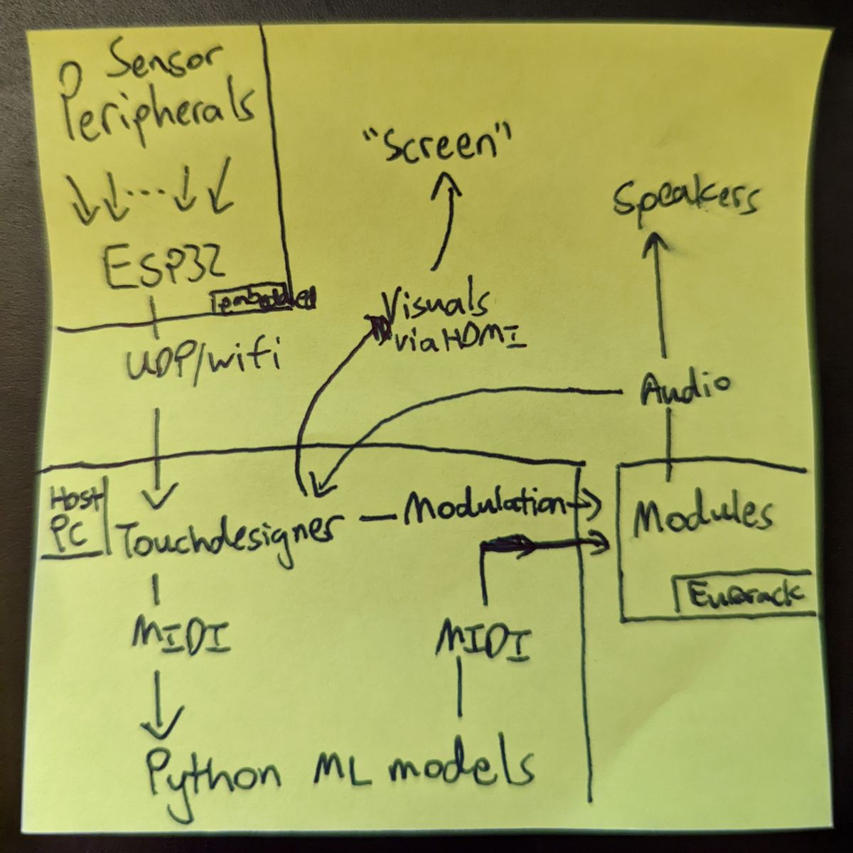
A core interest area of mine is the area where I can bring together machine learning, art, and technology in an interactive manner. I've recently been exploring generative arts, both with Eurorack modular synthesizers and visuals using TouchDesigner, more Eurorack, and GANs. I wanted to come up with something that would be playably interactive, but also aesthetically interesting. Recently, I've been inspired by faux-holographic effects using a technique referred to as Pepper's Ghost, as well as infinity mirrors/hypercubes. So I decided to pursue a more artistic and interactive final project that would serve as a testbed or prototype for what a future, larger-scale art installation could look like. It would serve as a cool audio visualizer for my electronic music livesets, with a dusting of machine learning magic and hopes for future art installs.I chose to incorporate all these ideas for a fairly unimaginative project name - Holosynthcube. Yup. It's holographic. It works with synths. It's a cube. Sorry, I'm not that creative! As a project that serves as a testbed for future art installations, I wanted to incorporate a higher level of systems integration than I had seen most of the class do or that I had done myself up to this point. After all, a finished product needs to "hide the magic" to suspend disbelief!
Draft Mockup & Detailed Conceptualization
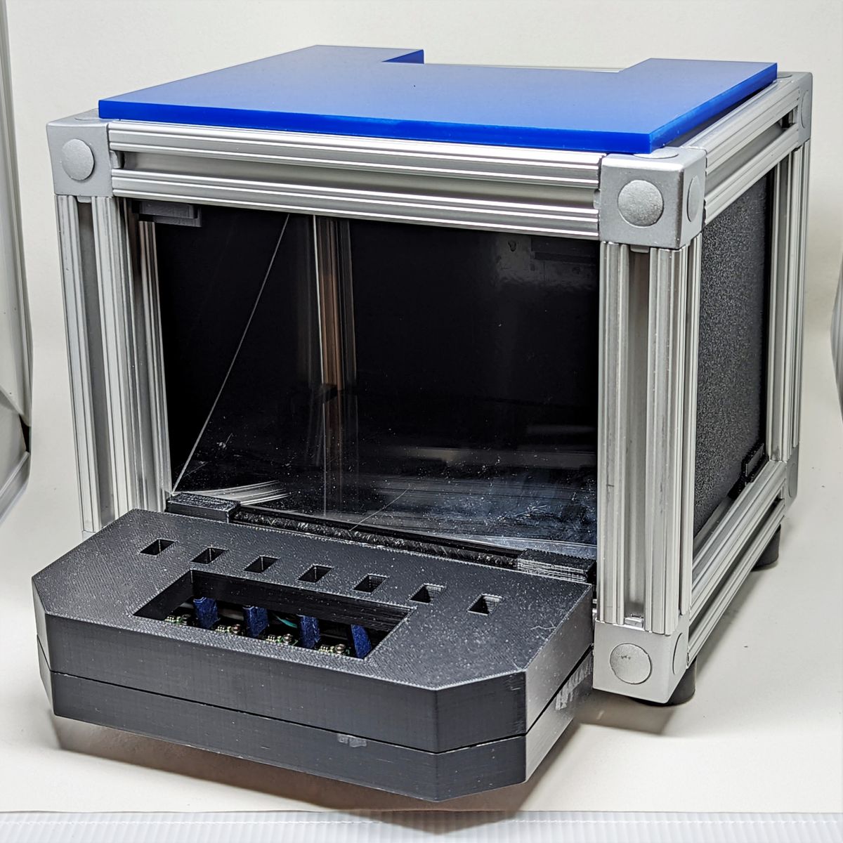
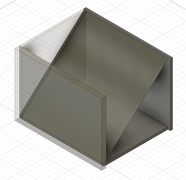
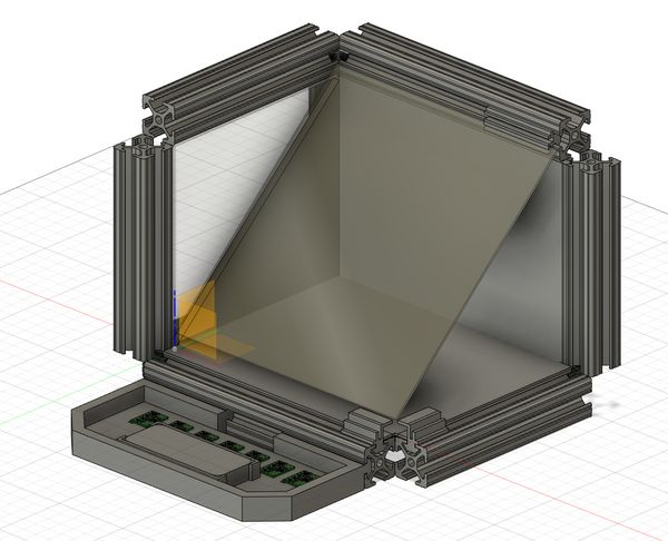
I drafted an idea of what the system might look like. Based on conversations with Anthony, he suggested that my high-level idea was "multiple projects", so I decided to scale down the holographics from a three-sided pyramid into effectively, a single-side, which would ease design and manufacturing. It would take the form of a cube with electronics integrated in its base, a 45-degree acrylic sheet in the center, and paneling all around and a screen as the top. A small chin would jut from the front base with integrated sensors.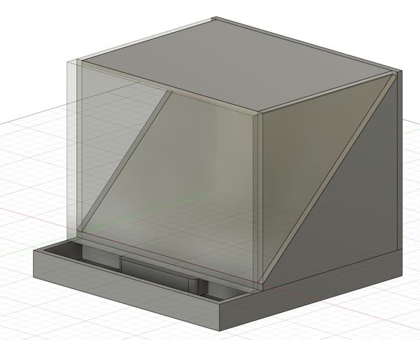
Fleshed Out Design & Materials Acquisition Woes
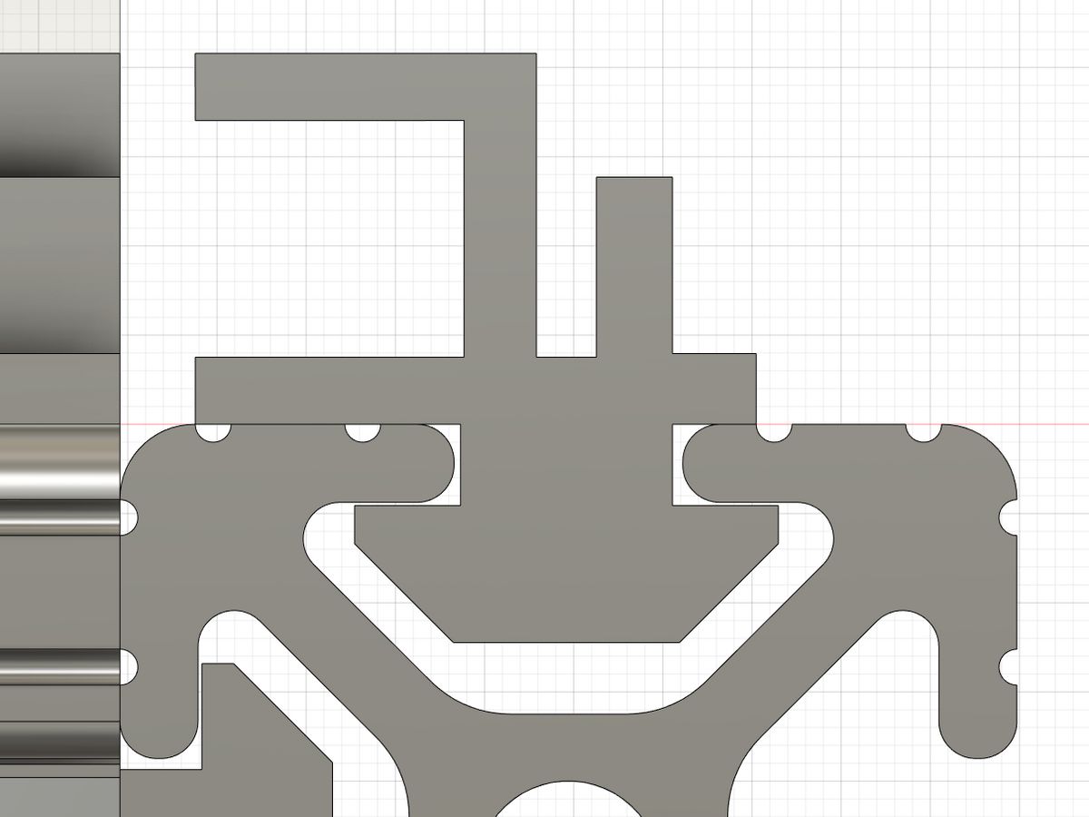
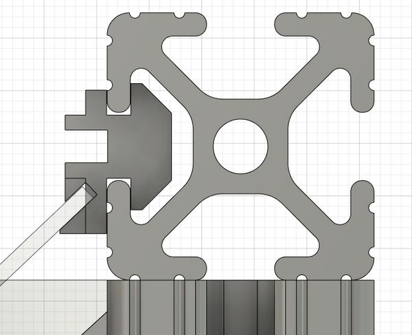
I decided that T-slot aluminum extrusion bars would provide the most flexibility in construction while remaining a fairly rigid structure. When trying to download and import McMaster-Carr's CAD models into Fusion360, I discovered that Fusion360 natively has a browser to search and import from their catalog! Armed with this in hand, I was able to CAD the rough structure of the cube, which gave me a better sense for how to design the rest of it.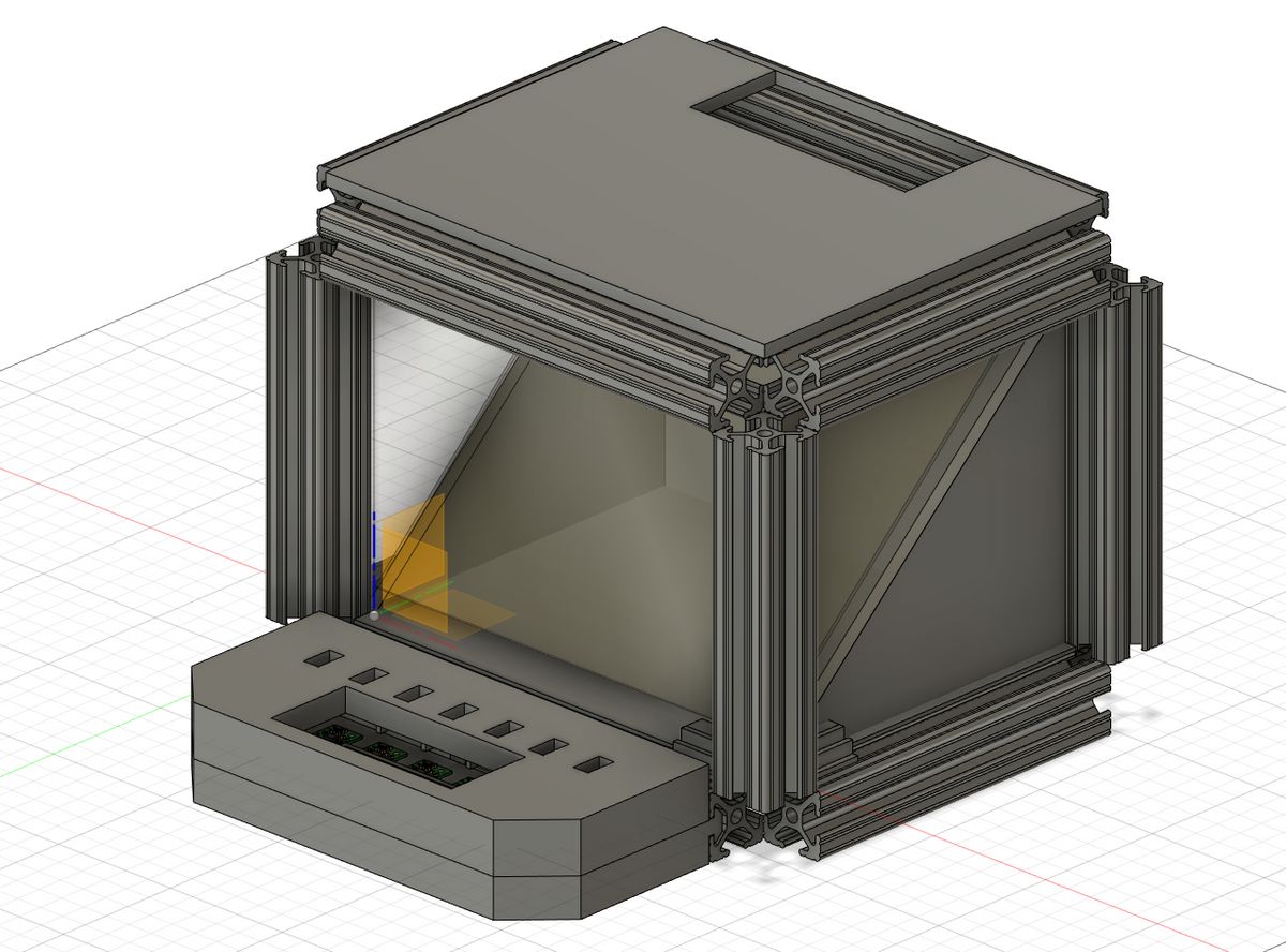
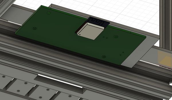
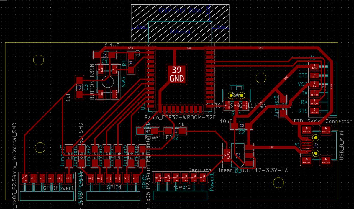
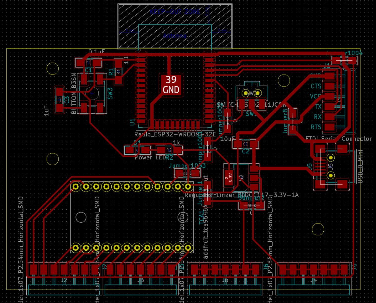
Finally, I used the same technique I had learned before by exporting my board design from KiCad and importing it into Fusion360, which allowed me to design a PCB carrier with screw holes in the proper positions that would fit underneath the baseplate.
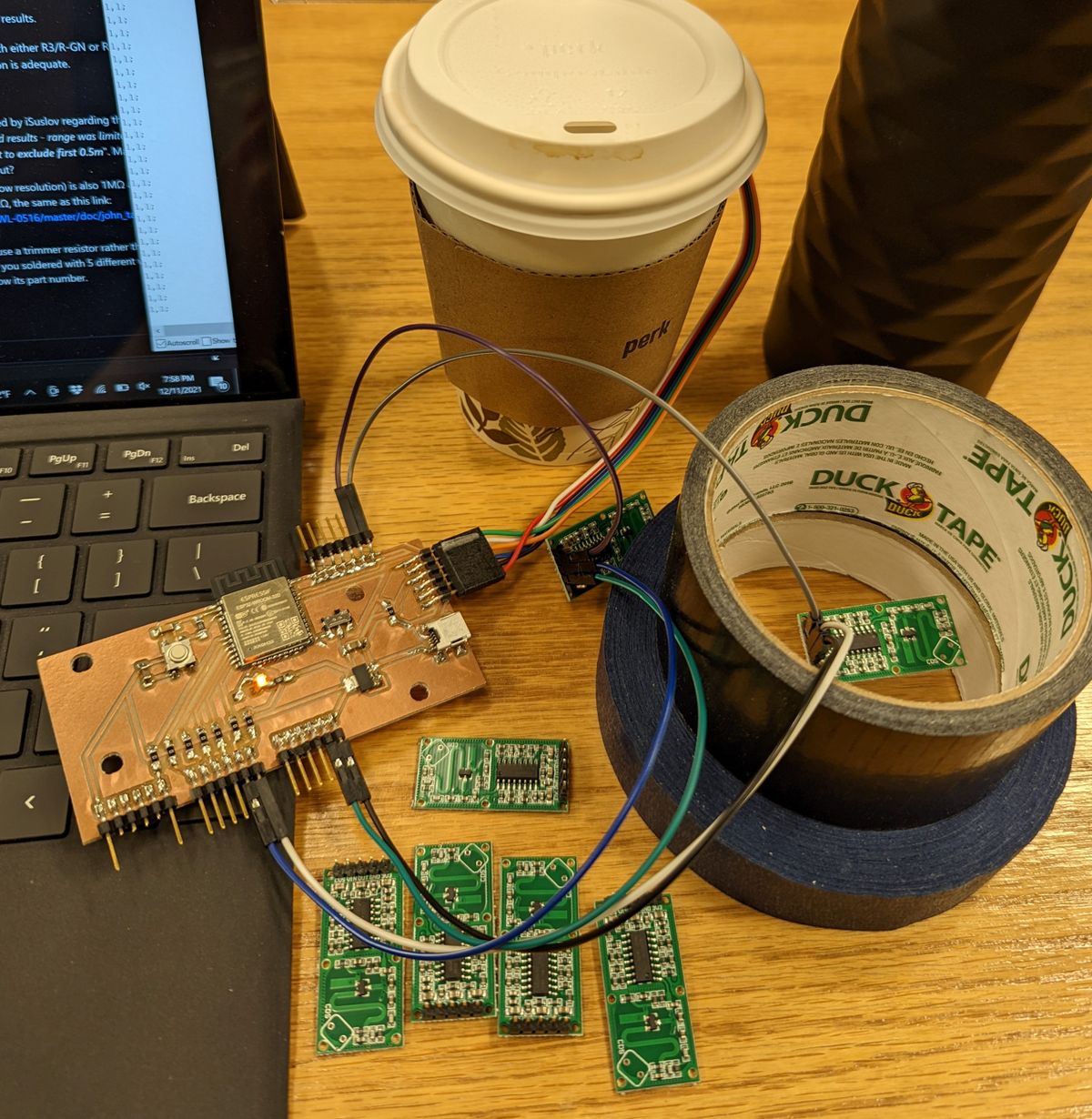
Unfortunately, my order of two-way mirror glass and high-reflective acrylic sheets ended up getting delayed by several weeks going into the final week of the project. When I tried to place replacement orders, the quickest delivery would have arrived on demo day, which meant that I had to make do with whatever clear acrylic scrap was available in EDS, and had to forgo the "infinity mirror" design on the sides. Additionally, EDS' delivery of time-of-flight (TOF) sensors never arrived, so I designed my system to use 7 RCWL-0516 Doppler radar sensors instead. I discuss the challenges with them later, but between salvaging three off of my Week 11/Week 12 boards and scavenging two from CBA, I could at least feature five. Luckily, the night before, Anthony was able to find the TOF sensors that did end up getting delivered.
The final BOM for the major components are as follows:
| Item | Quantity |
|---|---|
| 1"-side T-Slot Aluminum Extrusion | 2 Bars |
| T-Slot 3-Way Outside Corner End Bracket | 8 |
| Pololu VL53L1X Time-of-Flight Sensor | 7 |
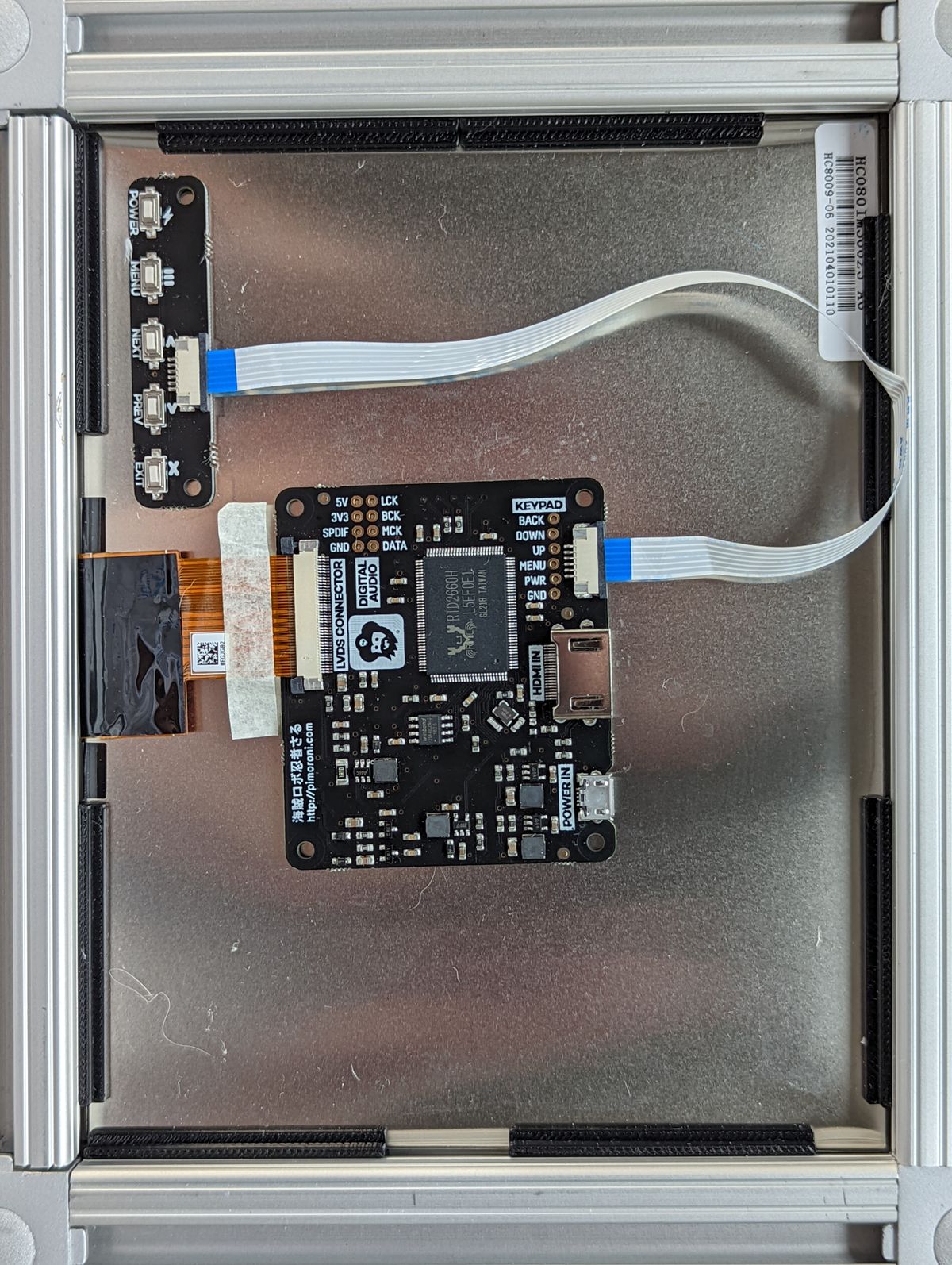
| Pimoroni HDMI 8" IPS LCD | 1 |
| Adafruit TCA9548A I2C Multiplexer | 1 |
| Leap Motion Controller | 1 |
| Acrylic Sheets | Scraps |
| Unidentified (ABS? Delrin?) Sheets | Scraps |
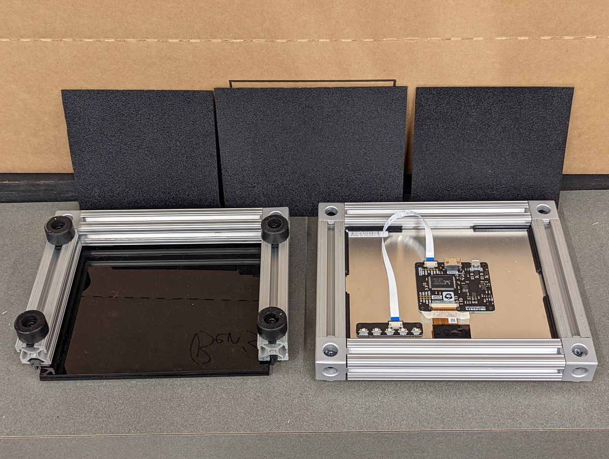
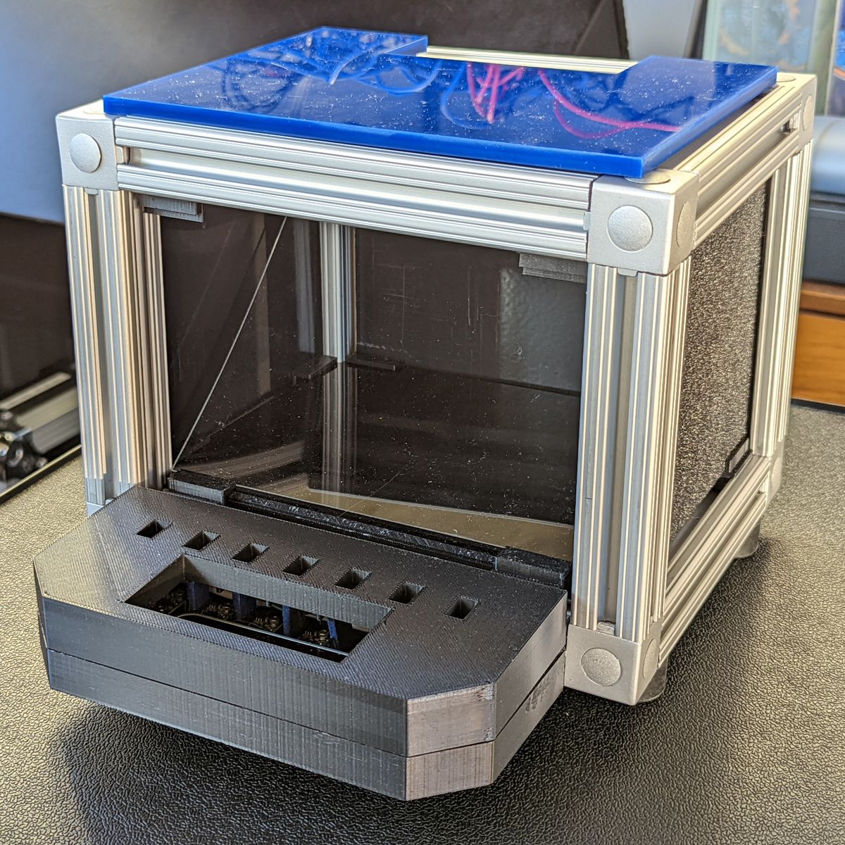
- Screen Subassembly
- Baseplate Subassembly
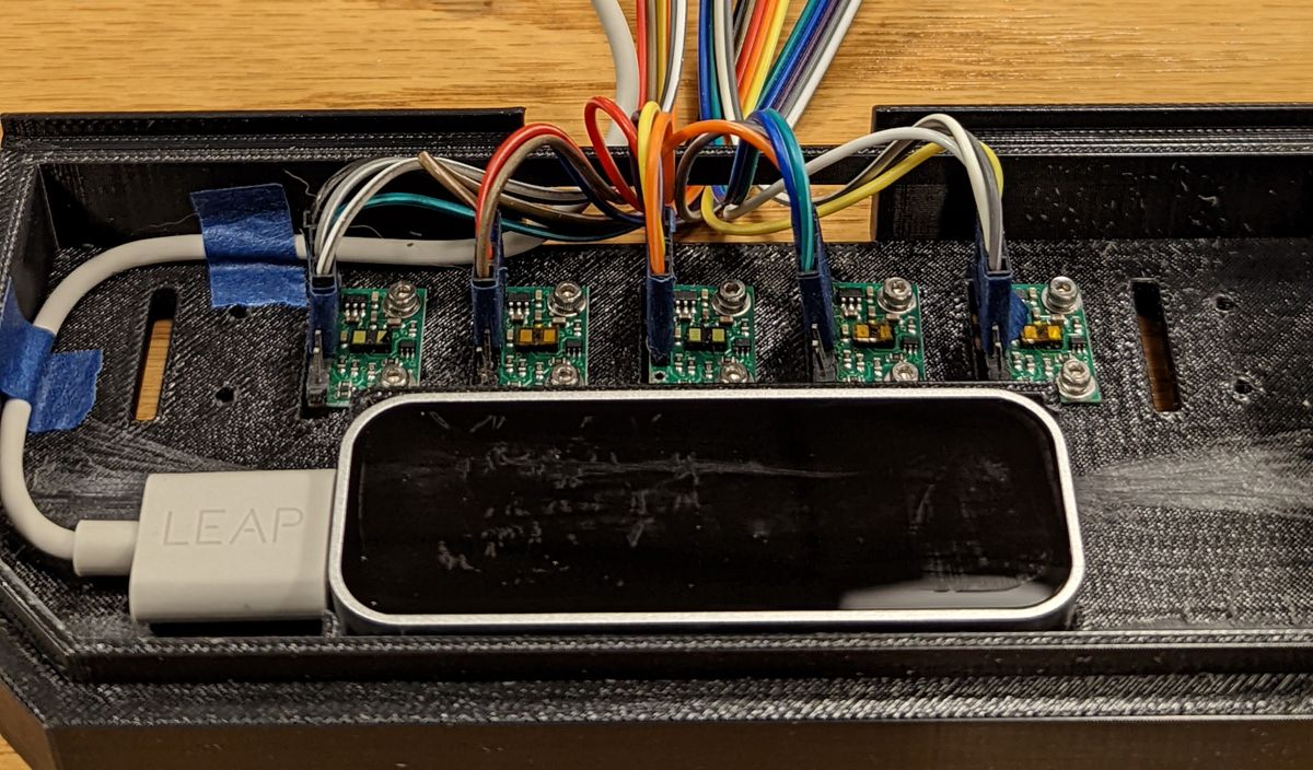
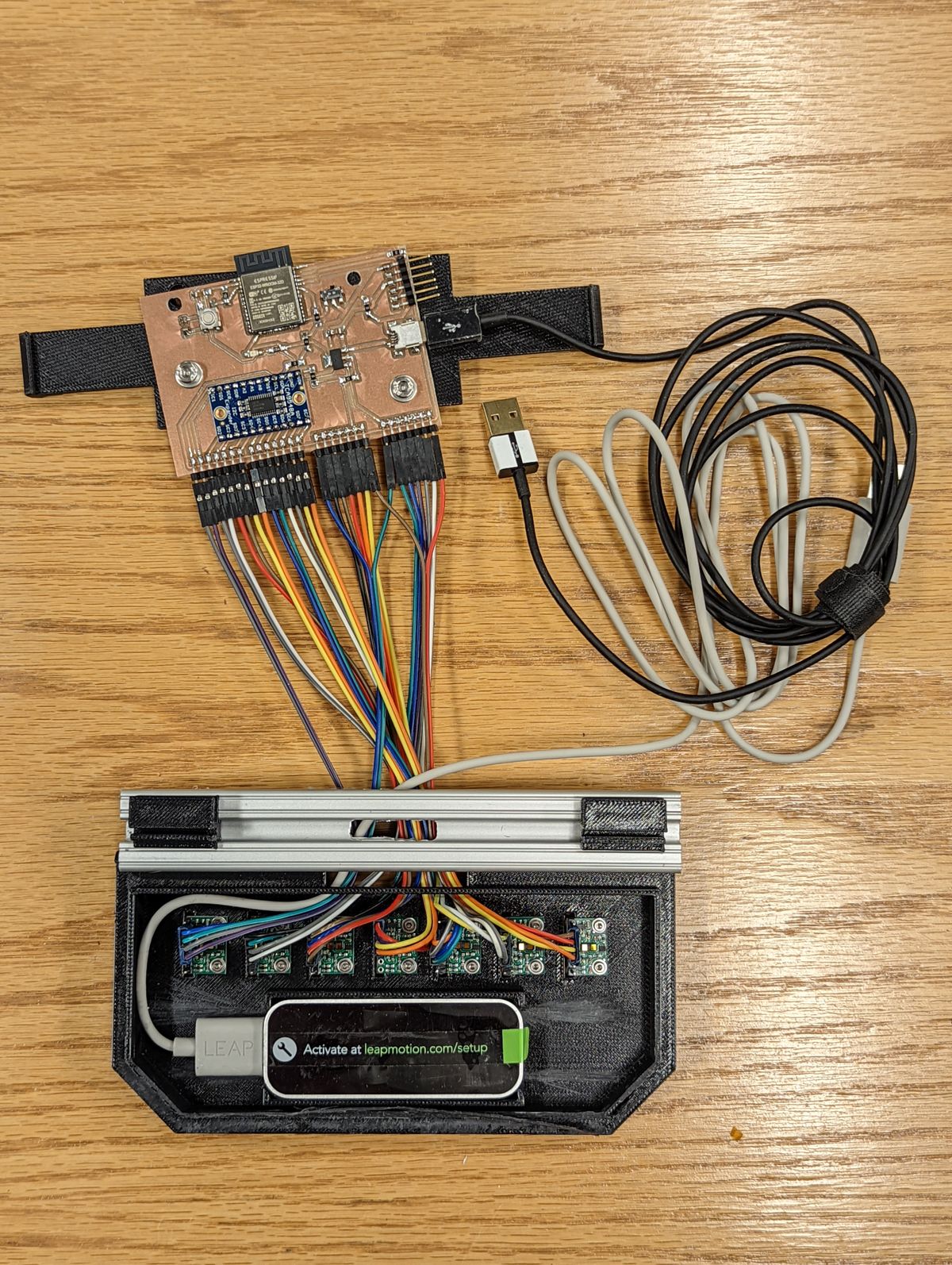
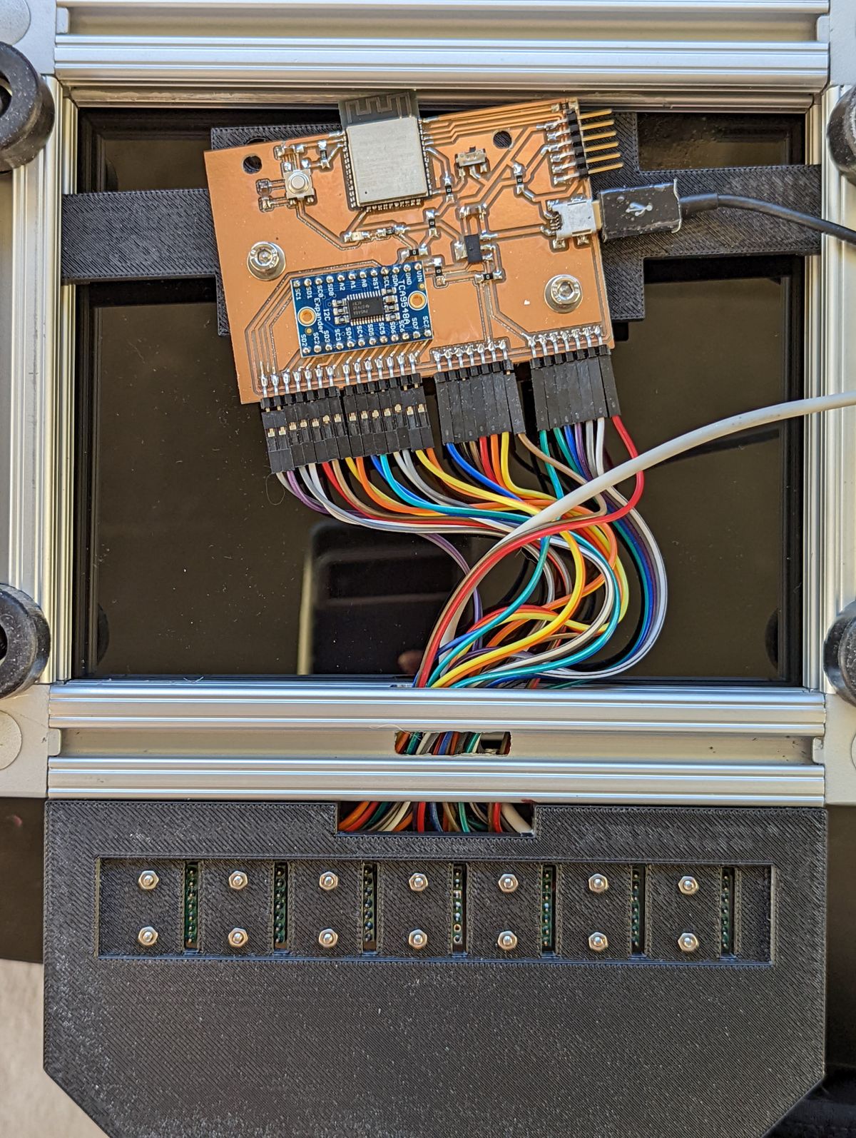
- Sensor Carrier & Electronics Subassembly
Chassis Fabrication
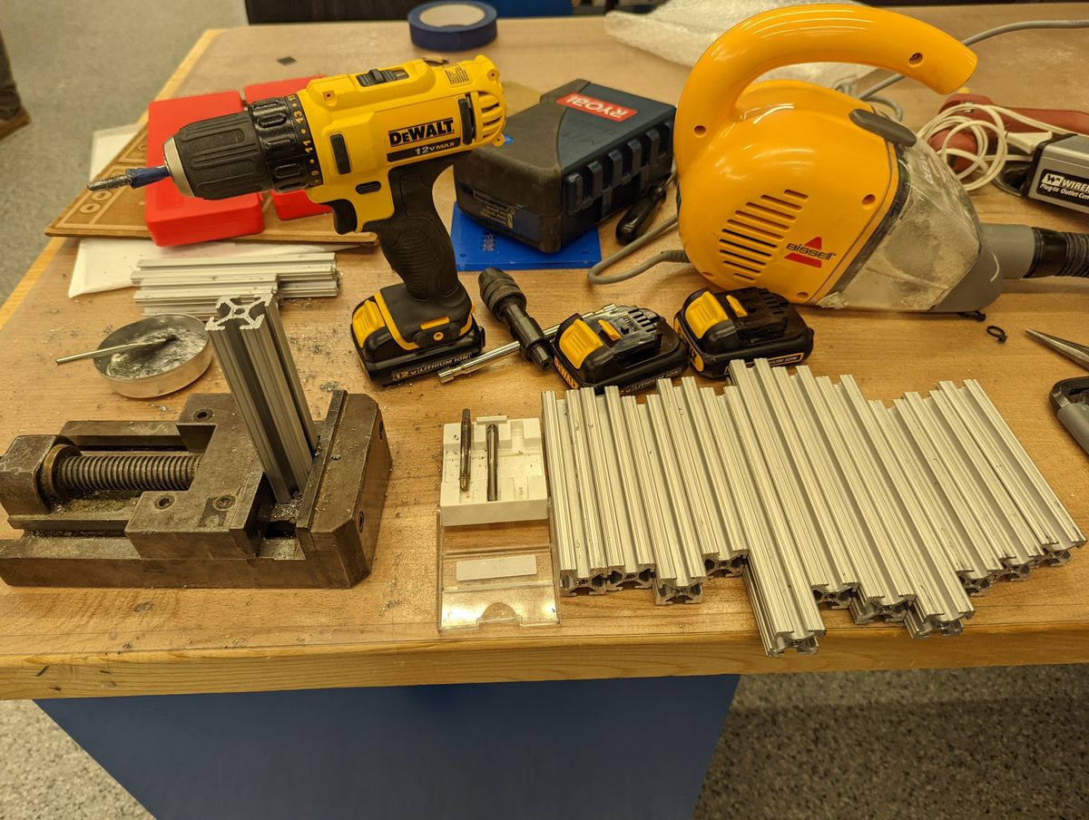
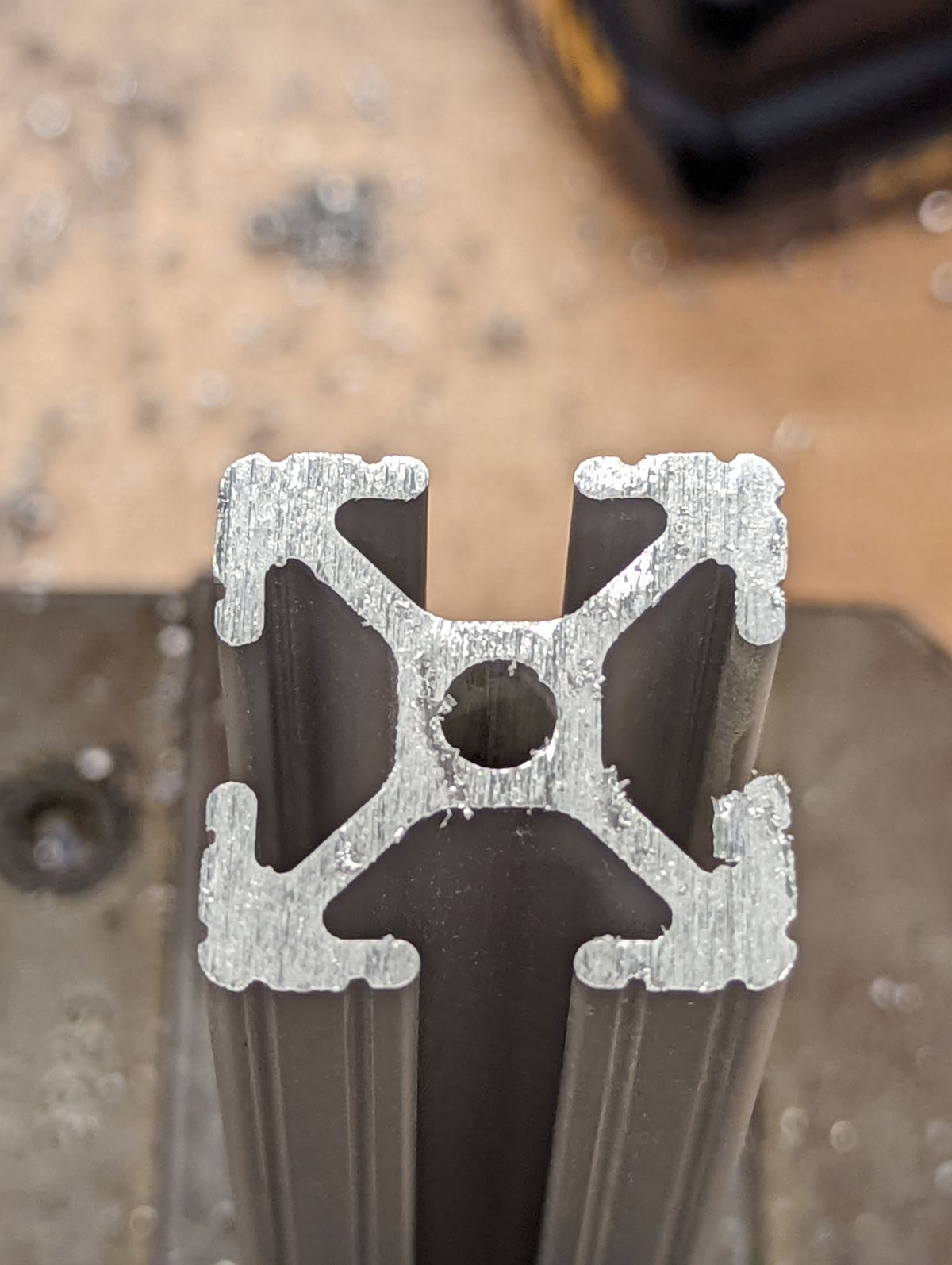
Painstakingly painfully. I was not pleased to hear from Anthony that the CBA shop had a stabilized pneumatic tapper that would've done this same job in minutes, and really wished that the EDS shop was better funded to support basic machine shop tools (seriously, how do we not have a belt or orbital sander?!)
With plenty of blisters, cuts, and cutting oil on my palms, I set aside the corresponding tapped bars and 3D printed brackets for each of the major subassemblies. Using the dimensions measured straight off of the CAD model, I bandsawed and deburred the unidentified plastic scrap sheets that would form the side and back walls of the cube. A sheet of blue acrylic was laser cut to serve as the top cover for the Screen Subassembly, with a slot for the HDMI and power cable for the screen. One clear sheet of acrylic was laser cut as the reflector panel. Two sheets of black acrylic were laser cut and glued together to serve as the baseplate (someone in our section had grabbed the original, thicker sheet I was planning to use when I had set it aside next to my box of parts, thinking it was freely available, and I didn't want to have to reprint the brackets). Finally, I 3D printed a housing for the sensor package.
Electronics/Sensor Package Design
The core design called for seven sensors that would each correspond to a white key on the middle C scale, with an ESP32 transmitting the data over UDP on an access point it hosts.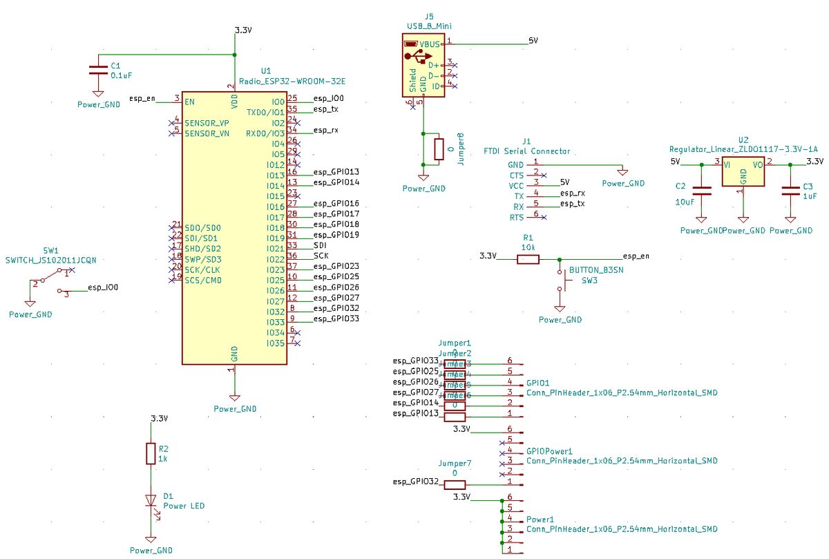
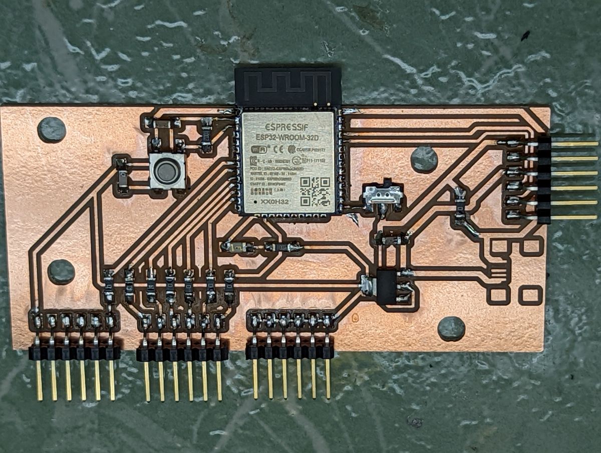
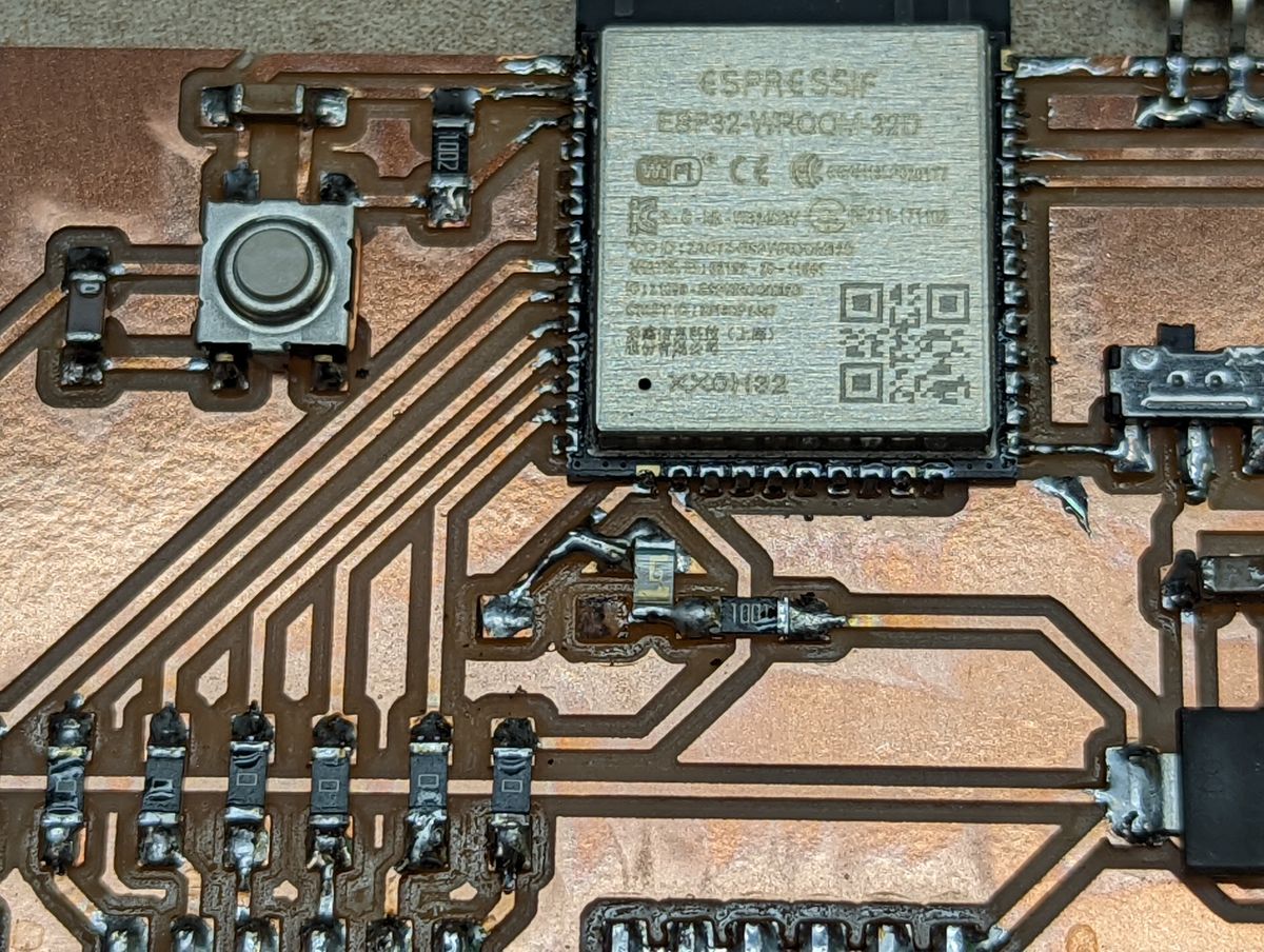
With the board populated and ready-to-go, it was time for testing. I wrote a quick script that would let me test two Doppler radar sensors in various obstructed and unobstructed setups for interference and sensitivity.
#include "Wire.h"
#define Sensor1 13
#define Sensor2 14

void setup() {
  Serial.begin(115200);
  Serial.println("Starting up...");
  pinMode(Sensor1, INPUT);
  pinMode(Sensor2, INPUT);
}

void loop() {
  int sensor1_val = digitalRead(Sensor1);
  int sensor2_val = digitalRead(Sensor2);
  Serial.print(sensor1_val);
  Serial.print(",");
  Serial.print(sensor2_val);
  Serial.println(";");
  delay(100);
}
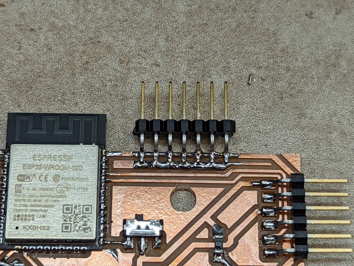
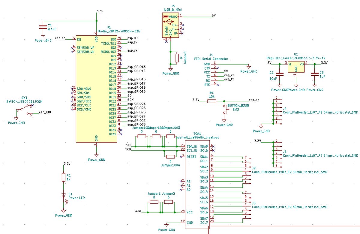
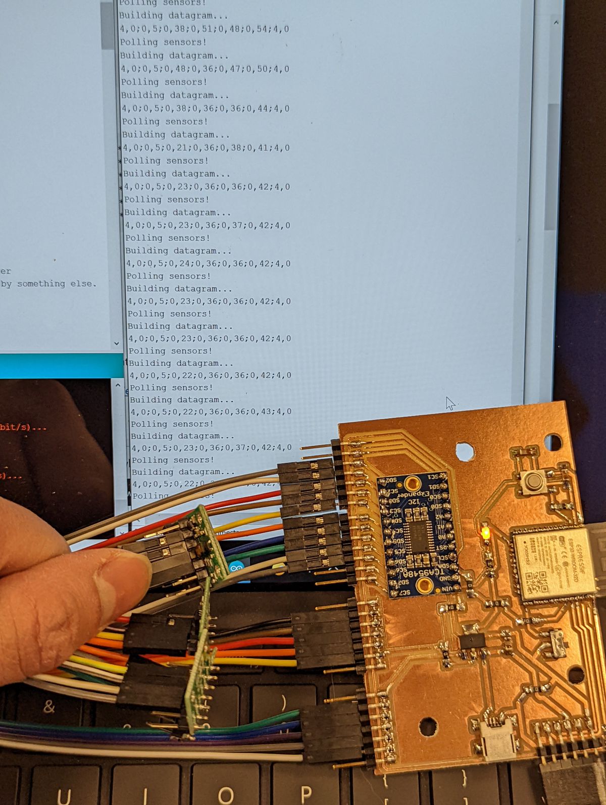
Through some salvaging and begging, I was able to acquire 5 of the original TOF sensors I had intended to use. I redesigned my board and rewrote my code, luckily relatively quickly, given my familiarity with these sensors from Week 11, including using an I2C multiplexer. This time, I ensured I had sufficient headers for power, ground, and I2C data/clock. However, I had still lost a lot of time from the previous board - time I did not have to spare. Even though I had 5 sensors, I chose to keep 7 headers in the event that more showed up.
#include <Wire.h>
#include <VL53L1X.h>
#include <WiFi.h>
#include <WiFiUdp.h>

#define MULTIPLEX 0x70
VL53L1X s_dist_1; // tca1
VL53L1X s_dist_2; // tca2
VL53L1X s_dist_3; // tca3
VL53L1X s_dist_4; // tca4
VL53L1X s_dist_5; // tca5
VL53L1X s_dist_6; // tca6
VL53L1X s_dist_7; // tca7comp

#define WIFI_SSID [REDACTED]
#define WIFI_PASS [REDACTED]
WiFiServer server(80);

WiFiUDP UDP;
char packet[255];

const char ip[]="192.168.4.2";
#define UDP_PORT 4210

void tcaselect(uint8_t i) {
    if (i > 7) return;

    Wire.beginTransmission(MULTIPLEX);
    Wire.write(1 << i);
    Wire.endTransmission();
}

void setup()
{
    Serial.begin(115200);

    Serial.println("Starting up...");
    Serial.println("Initializing AP...");
    WiFi.softAP(WIFI_SSID, WIFI_PASS);
    Serial.println("");
    Serial.println("AP established, connected.");
    Serial.print("IP address: ");
    Serial.println(WiFi.softAPIP());
    server.begin();
    UDP.begin(UDP_PORT);


    Wire.begin();
    delay(1000);
    Serial.println("\nI2C Scanner ready!");

    for (uint8_t t=0; t<8; t++) {
    tcaselect(t);
    Serial.print("TCA9548A Port #"); Serial.println(t);

    for (uint8_t addr = 0; addr<=127; addr++) {
        if (addr == MULTIPLEX) continue;

        Wire.beginTransmission(addr);
        if (!Wire.endTransmission()) {
        Serial.print("  > Found I2C at address X0x");
        Serial.println(addr,HEX);
        }
    }
    }
    Serial.println("\nI2C Scan complete!");

    tcaselect(1);
    s_dist_1.setTimeout(500);
    s_dist_1.init();
    s_dist_1.setDistanceMode(VL53L1X::Short);
    s_dist_1.setMeasurementTimingBudget(140000);
    s_dist_1.startContinuous(140);

    tcaselect(2);
    s_dist_2.setTimeout(500);
    s_dist_2.init();
    s_dist_2.setDistanceMode(VL53L1X::Short);
    s_dist_2.setMeasurementTimingBudget(140000);
    s_dist_2.startContinuous(140);

    tcaselect(3);
    s_dist_3.setTimeout(500);
    s_dist_3.init();
    s_dist_3.setDistanceMode(VL53L1X::Short);
    s_dist_3.setMeasurementTimingBudget(140000);
    s_dist_3.startContinuous(140);

    tcaselect(4);
    s_dist_4.setTimeout(500);
    s_dist_4.init();
    s_dist_4.setDistanceMode(VL53L1X::Short);
    s_dist_4.setMeasurementTimingBudget(140000);
    s_dist_4.startContinuous(140);

    tcaselect(5);
    s_dist_5.setTimeout(500);
    s_dist_5.init();
    s_dist_5.setDistanceMode(VL53L1X::Short);
    s_dist_5.setMeasurementTimingBudget(140000);
    s_dist_5.startContinuous(140);

    tcaselect(6);
    s_dist_6.setTimeout(500);
    s_dist_6.init();
    s_dist_6.setDistanceMode(VL53L1X::Short);
    s_dist_6.setMeasurementTimingBudget(140000);
    s_dist_6.startContinuous(140);

    tcaselect(7);
    s_dist_7.setTimeout(500);
    s_dist_7.init();
    s_dist_7.setDistanceMode(VL53L1X::Short);
    s_dist_7.setMeasurementTimingBudget(140000);
    s_dist_7.startContinuous(140);

    Serial.println("\nSetup complete!");
}

void loop() {
    tcaselect(1);
    s_dist_1.read();
    tcaselect(2);
    s_dist_2.read();
    tcaselect(3);
    s_dist_3.read();
    tcaselect(4);
    s_dist_4.read();
    tcaselect(5);
    s_dist_5.read();
    tcaselect(6);
    s_dist_6.read();
    tcaselect(7);
    s_dist_7.read();
    String datagram = "";
    datagram += (String)s_dist_1.ranging_data.range_status + ",";
    datagram += (String)s_dist_1.ranging_data.range_mm + ";";
    datagram += (String)s_dist_2.ranging_data.range_status + ",";
    datagram += (String)s_dist_2.ranging_data.range_mm + ";";
    datagram += (String)s_dist_3.ranging_data.range_status + ",";
    datagram += (String)s_dist_3.ranging_data.range_mm + ";";
    datagram += (String)s_dist_4.ranging_data.range_status + ",";
    datagram += (String)s_dist_4.ranging_data.range_mm + ";";
    datagram += (String)s_dist_5.ranging_data.range_status + ",";
    datagram += (String)s_dist_5.ranging_data.range_mm + ";";
    datagram += (String)s_dist_6.ranging_data.range_status + ",";
    datagram += (String)s_dist_6.ranging_data.range_mm + ";";
    datagram += (String)s_dist_7.ranging_data.range_status + ",";
    datagram += (String)s_dist_7.ranging_data.range_mm + ";";
    datagram.toCharArray(packet, datagram.length() );
    UDP.beginPacket(ip, UDP_PORT);
    UDP.print(packet);
    UDP.endPacket();

    Serial.println(packet);
}
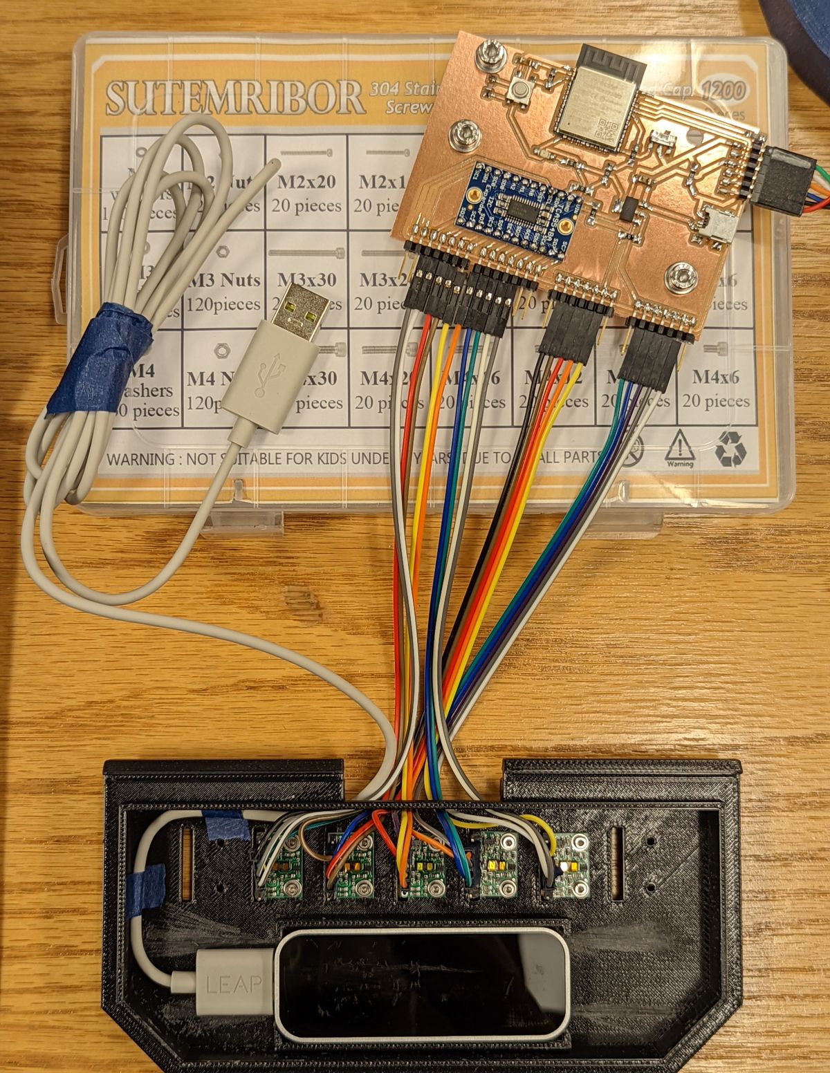
Subassembly & Systems Integration
Visualization & TouchDesigner Integration
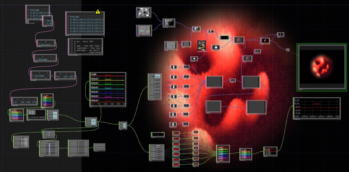
On the visual side, a simple fine- and coarse-grain noisemap were stacked and traversed in a pseudo-random manner, color mapped, and ran through a Rutt-Etra style 3D mapping process. This was combined with a feedback map and a shape map that tied together the whole visual effect to look like a dancing ball of lava. The Leap Motion's sensor data was parsed to receive X/Y/Z rotation of the palm, which correspondingly controlled the rotation of "lava ball". Overlaid on top were seven bars, each corresponding to a TOF sensor that would provide visual feedback on the control being "interacted with".
By clamping the range and normalizing the inputs, I was able to get fairly desireable amounts of control modulation.
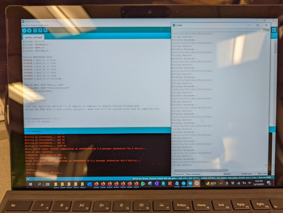
Using a larger screen allows for more fine-tuning and debugging of the various sensors and controls.
Finally, I checked the interaction to see if it was roughly the experience I expected it to be, and it is in the ballpark of what I expected.
Final System
I suspected further damage, especially when the sensors failed to work after setup. However, I realize now that the system had only been tested in normal lighting conditions - during demo day, my station was in very bright direct sunlight, which appears to have played merry hell with both the TOF sensors and the Leap Motion. I later verified this by disassembling and testing each electronic component individually. The only other damage suffered was that the first TOF sensor did appear to have died, sending back an unchanging distance reading and a status code indicating it was operating OK. This sensor was checked with other channels and confirmed to be an issue with the sensor itself.
Perhaps related to the missing sensor, the TensorFlow/Magenta model started behaving erratically, and thus I disabled it for the below demo videos.
Reflections & Fun Facts
There are definitely areas where the cube could be improved. A better screen that's brighter would go a long way, OLED if possible for true blacks. Additionally, I suspect that the lack of "3D-ness" comes down to the much smaller scale - since the depth of the perceived image is the same as the distance from the screen to the reflector, a cube performs poorly in this regard. A much further rear wall would have improved the illusion of holography. The material seems to also affect the perception of three-dimensionality - a 3D image augments the illusion. Additionally, I had been spending so evenings working on this that I had never tested it in daylight, which meant that the first time it saw daylight was demo day. I'll certainly remember to test optically-based systems in various lighting conditions in the future. Lastly, I need to remember that the more rigid a structure is, the better it passes on shocks - the screen might not have cracked if it wasn't being held so firmly!- I lost four days of working on the project to my covid-19 booster - I had moved it to avoid an exam, but forgot about the final project!
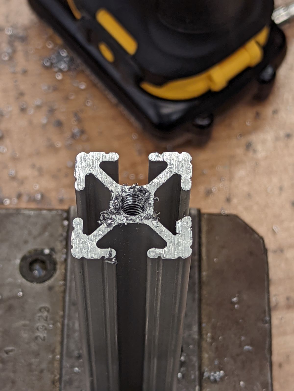
- Between test runs and re-works, I physically tapped over 60 screw holes over the course of several hours - more than I would ever like to for the rest of my life
- I broke one of the tapping ends by hand while tapping one of the last aluminum bars
- Anthony taught me that you can actually tap with a powertool, as long as the tap is large enough
- The thorough CAD model allowed for some very precise machining and 3D printing jobs
- I plan to iterate on the screen and sensors a bit more, and want to use it as part of a live performance setup
- I printed over 24 hours of jobs on the Stratasys F120
- My reflective sheets that were delayed still haven't arrived!
- I learned how to use the Bridgeport to drill and mill - I had never used such a big drillpress prior!
- The Bridgeport in the EDS shop is older than my home country, Singapore :o
- I am well aware that despite the sensors running over wifi, I still have a USB connection for the Leap Motion and an HDMI connection for the screen - so I cannot truly be untethered from the host computer :)
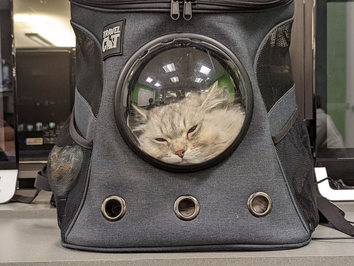
Moral Support Cat
Final Project Week would not have been possible without the ever-affectionate cheerleader, Atlas the Siberian, who kept us company in the EDS Conference Room during long days and nights.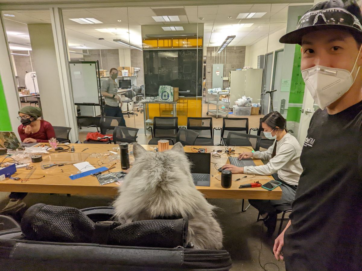

Previous Ideas
I initially started out wanting to do some sort of a 3D data visualizer using a pin-based system. Unfortunately, I discovered that this exact idea had been completely and thoroughly executed on several years before by MIT Media Lab's Tangible Media Group.Sad.
I thought about implementing something using acoustic levitation, but the more I looked into it, the more I realized how out-of-depth I was in the physics, and how challenging it was to construct even for experts in the field. Electromagnetic levitation was another idea, but at this point I realized that these advanced physics techniques are probably out of league of my current capabilities. Maybe as a future technology exploration project I might be able to construct something small-scale to test, but not for a capstone final project for HTMaA.
More sad.
I came across a holographic audio visualizer, but it seemed rather straightforward and uninteresting to implement.
Somewhat cooler was a Volumetric OLED display, but that was already incredibly expensive parts-wise, without even considering scaling it up to a larger display due to the cost of transparent OLEDs. Some other inspirations I also came across, and started looking at the visualizer concept more: