Design
Using Eeschema in Kicad
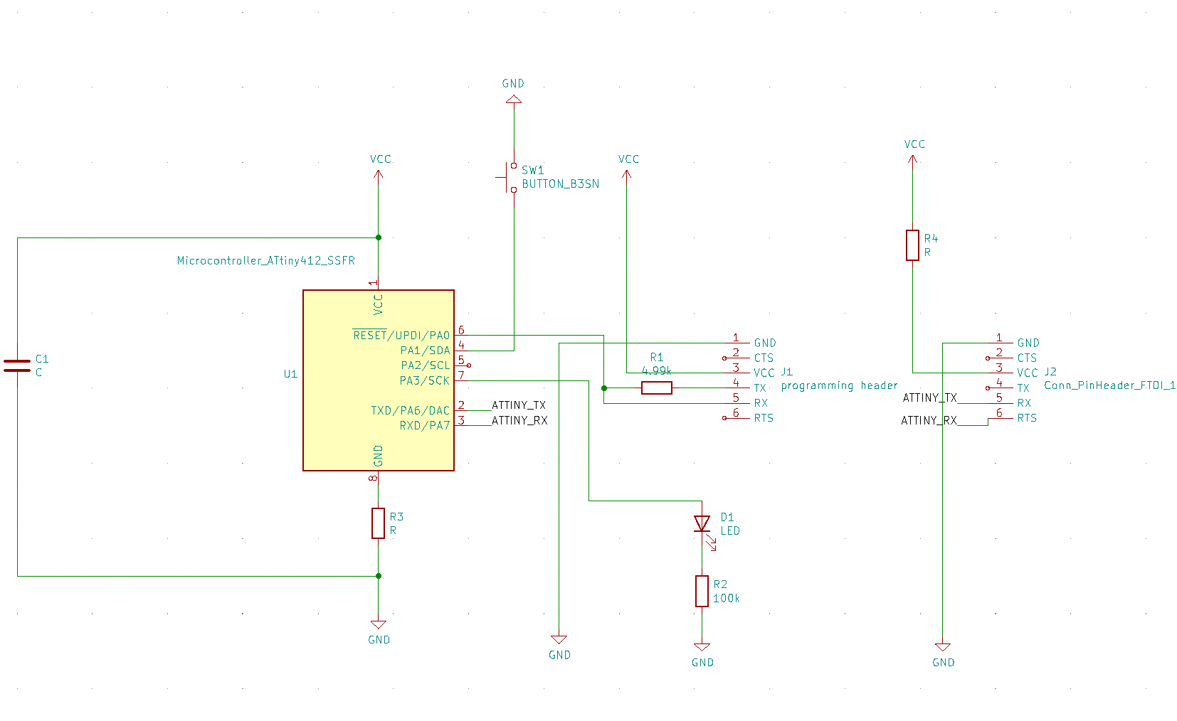
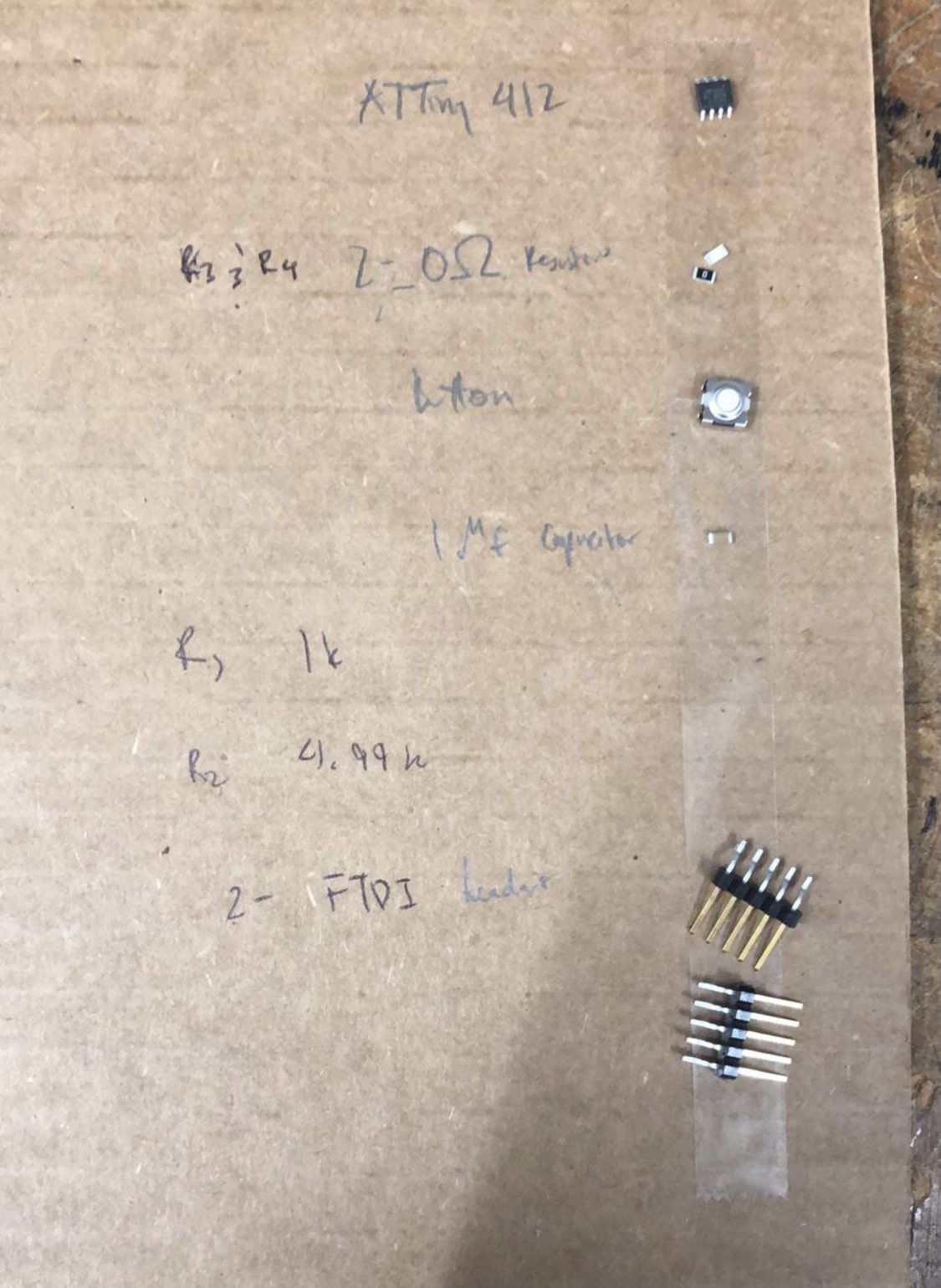
I decided to use KiCad for the design part of this week’s assignment. I started by following __’s recitation in mapping the components of a 412 board. I then added in the button and LED, and an extra resistor before routing the LED to the ground. I then created a netlist by first assigning footprints with the fab library and annotating my components.
Laying out the PCB
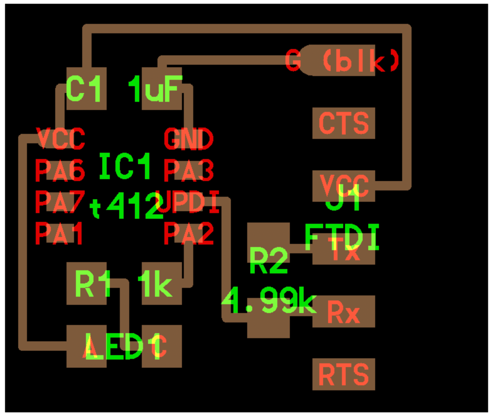
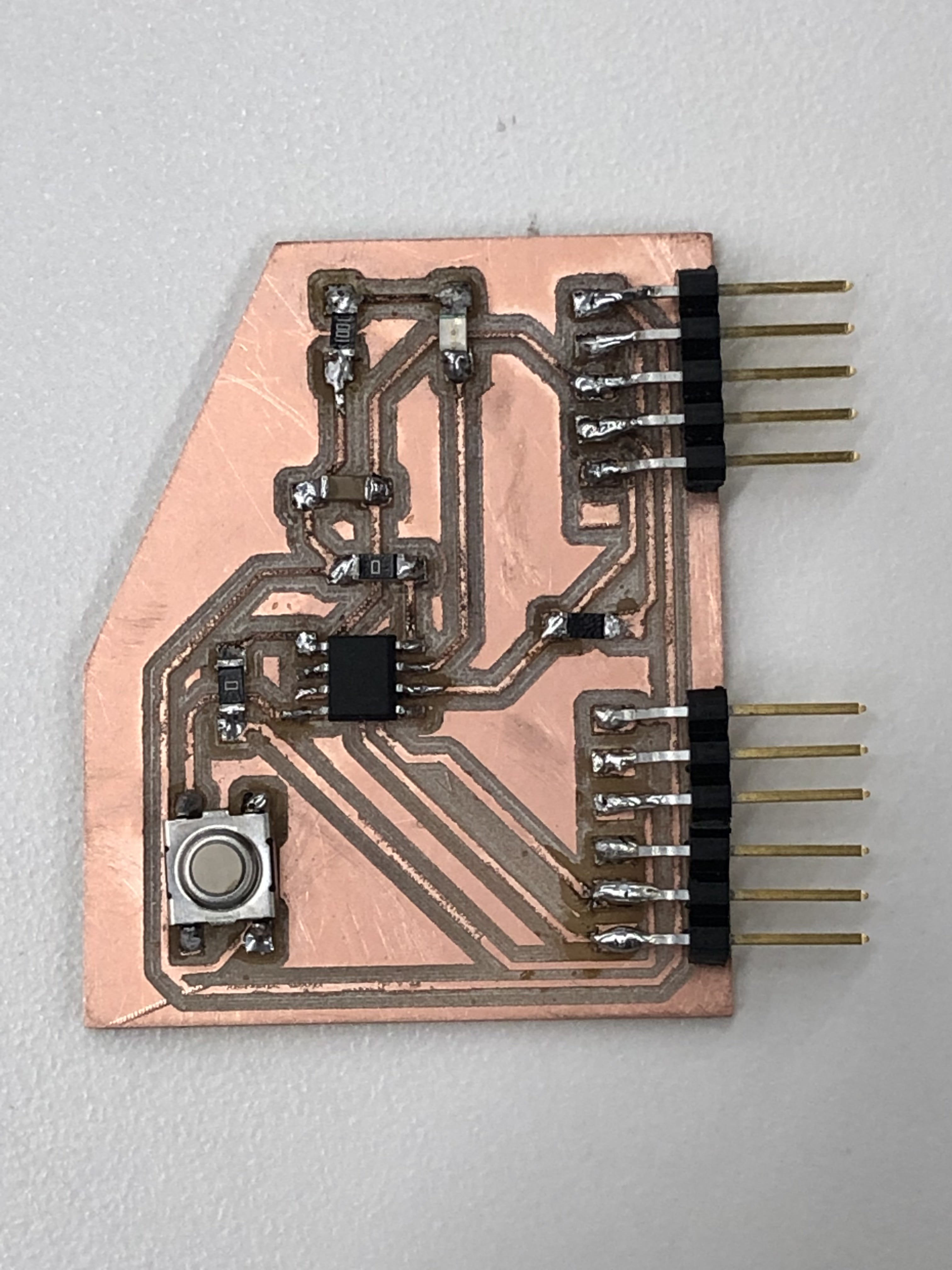
I then laid out the PCB, which took a long time because I was trying to minimize the number of crossings on my board. I used 0.50 mm traces, with 0.50 mm clearance(to provide room for the 0.397 mm from the 1/64" endmill). I ended up prioritizing the microcontroller routes first, and then worried about the outside pin headers later. I ended up only having to add 2 0-ohm jumper resistors to cross over traces.
I added 2 jumper resistors to be able to cross over traces without intersecting.
Exporting
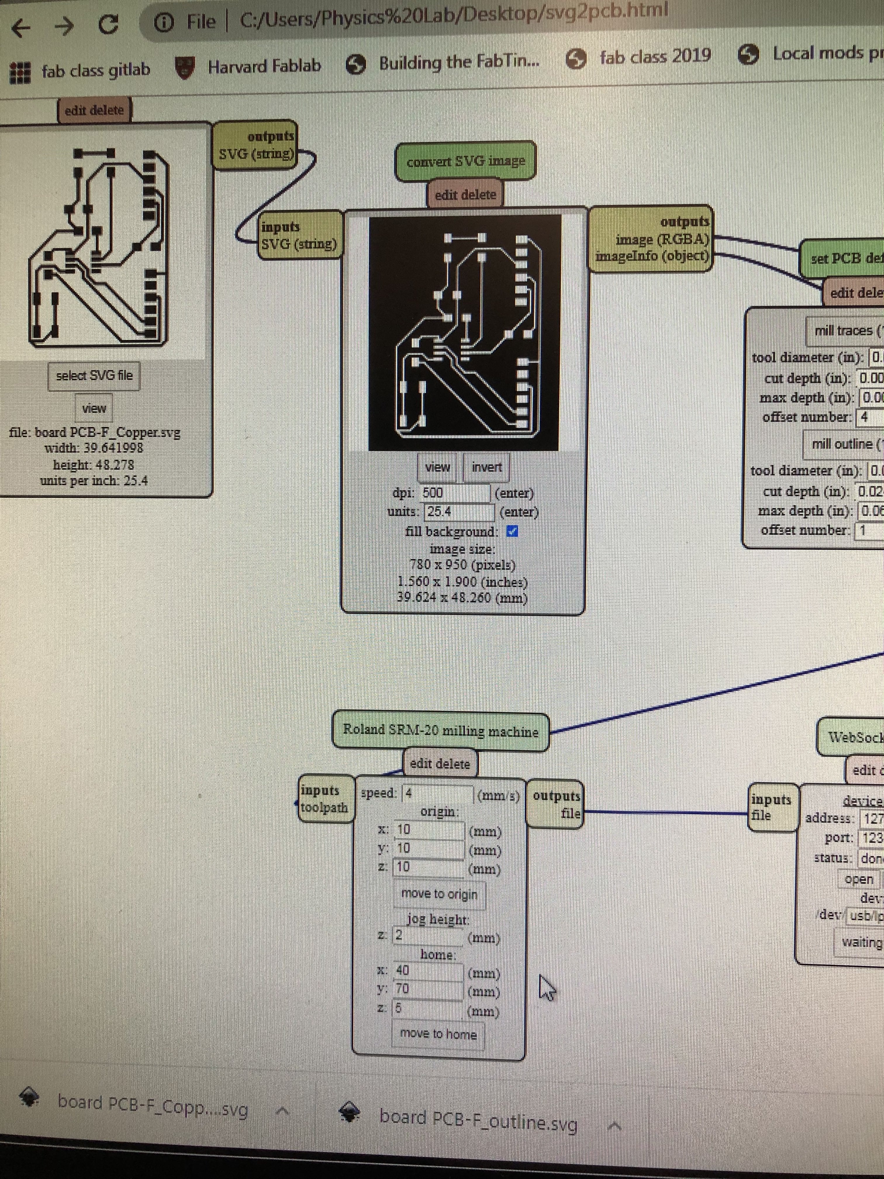
I then exported the svg file to inkscape. I adjusted the dimensions so that the image would match the actual size of the contents, and added a 1 mm border in case of any mistakes. I separated the outline and traces into different layers, and then exported them separately to be used with the mod.
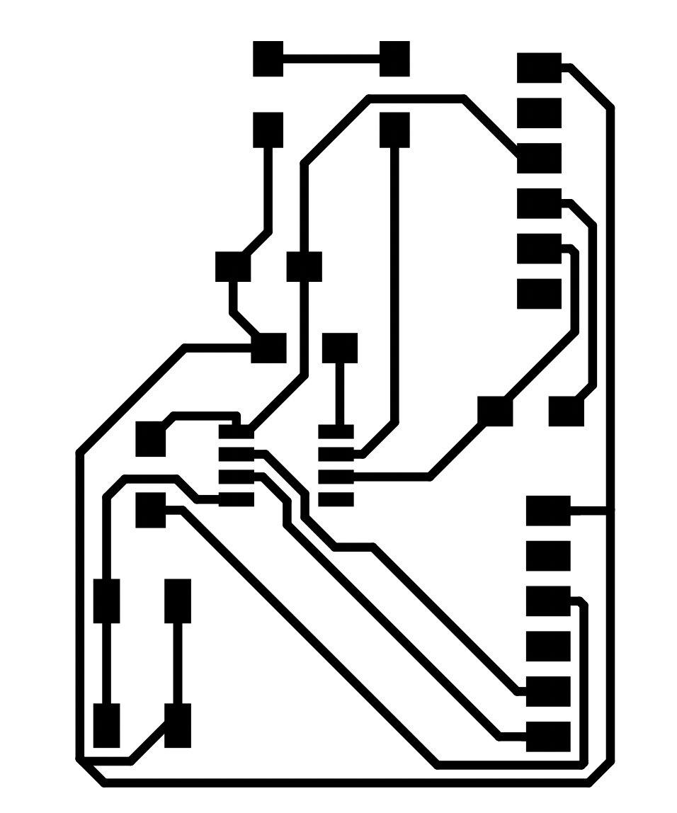

These are the two separated layers.
Board Fabrication
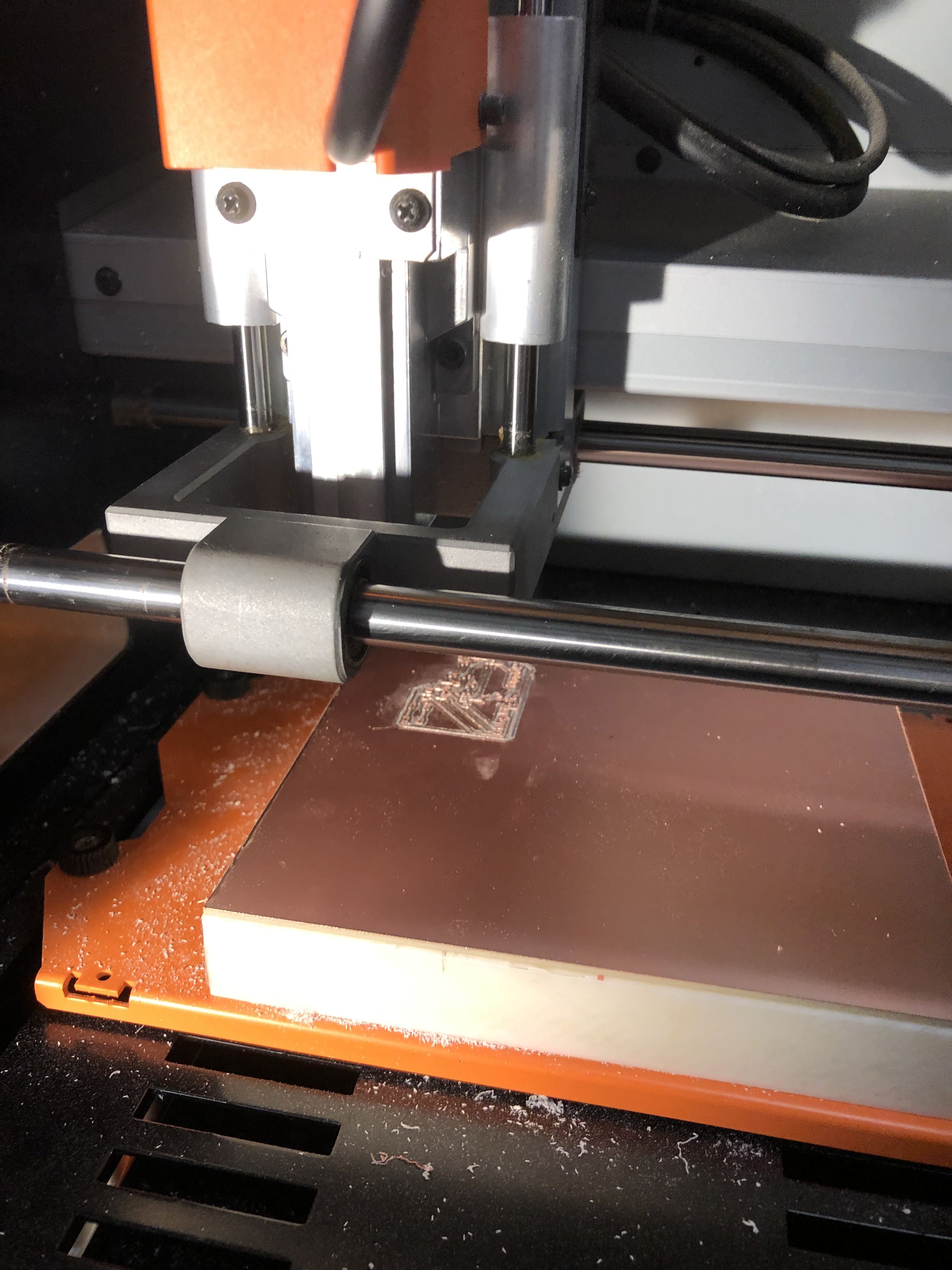
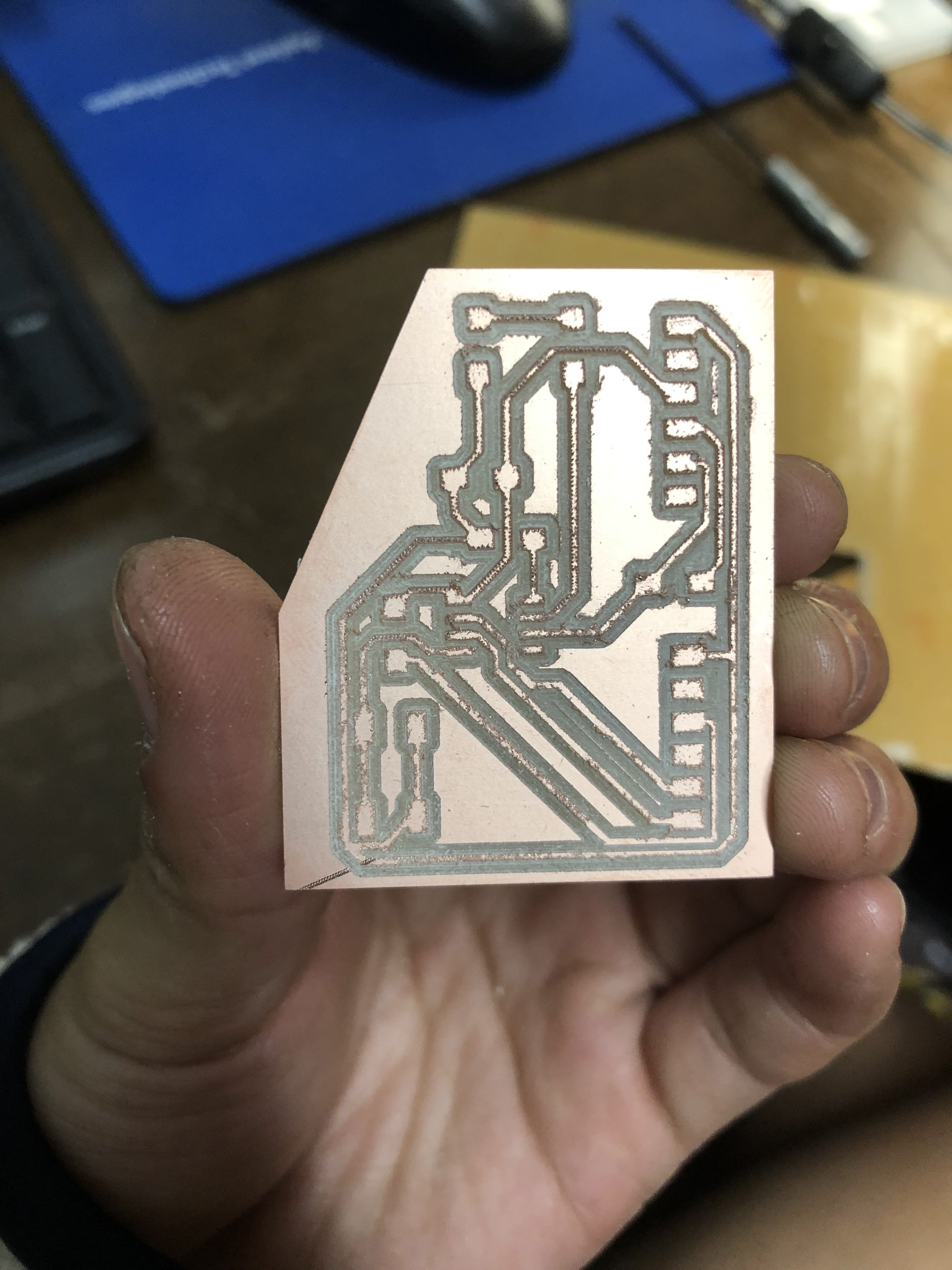
Milling
The milling process for these boards actually went by quite smoothly, but the end result was quite jagged, which could be due to the milling bit being old and used all week. I noticed that the board started lifting slightly, but not to a point where it drastically affected the final board. I would like to play around with the offset number, as the board was milled too deeply.
Soldering
I then soldered on all the parts. I noticed that we only had 5 pin FTDI’s rather than 6, so I broke apart 2 into 3 pins and soldered them together. I also noticed the other one of my pins wasn’t using the 6th pin, so I just used the 5 pin.
Programming
Testing
Rob came into the lab Tuesday night, so I was able to solicit his help in programming and testing my board. I first tested the resistance across the board with a multimeter so that it would beep every time the needles landed on the same pathway on the circuit. This let me see any issues with my board before programming, and thankfully all my pins were routed correctly.
Programming
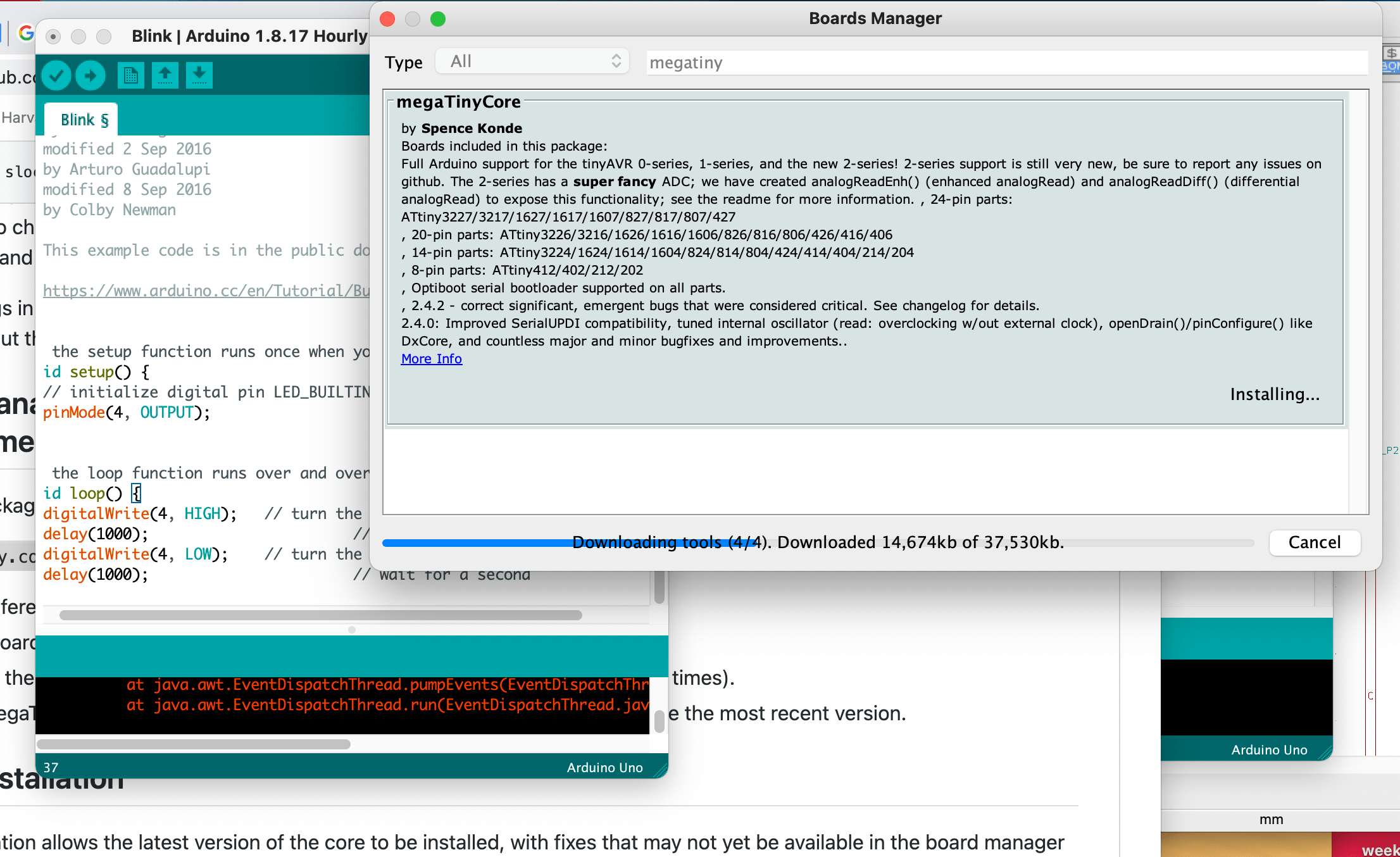
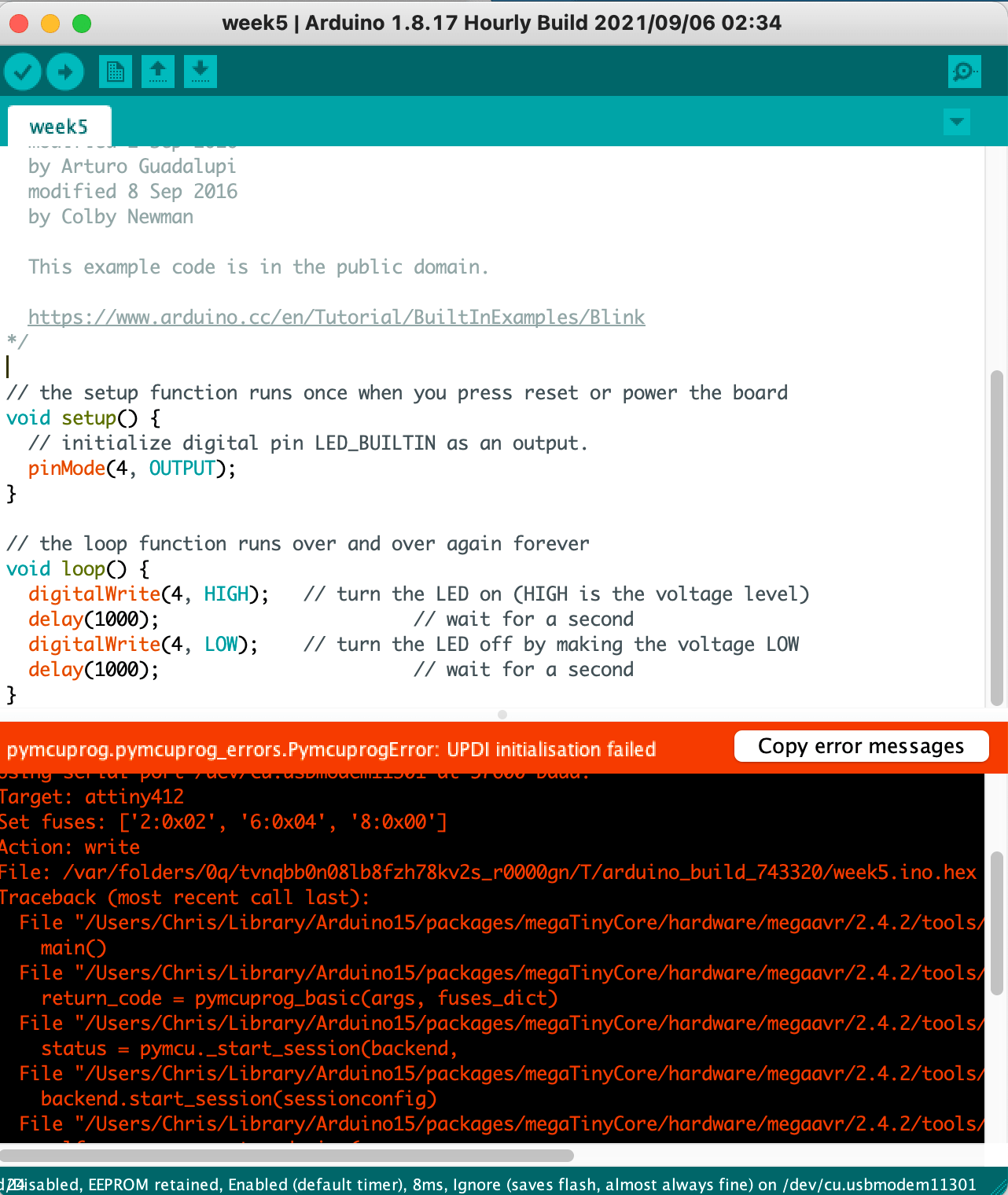
I then downloaded Arduino and downloaded some tools to program my board like the board plugin on gitlab, and since I was using an ATTiny 412 I only needed to use Rob’s USB serial adapter to send information to my board without having to bootload. I used example code from the Arduino interface to write a blink program, which would make the LED on my board blink when I pressed the button. I replaced the “LED_BUILTIN” with pin #4, the analog number that I found when I looked at the diagram for ATTiny series-1 for port pin PA6.
Unfortunately, after many tries, my board did not program successfully when it couldn't initialize. I troubleshooted by using the multimeter again, but after not finding anything wrong with my board physically, I decided to find a later time to rebuild the board.
 Board (KiCad Project .ZIP)