Week 11: Interface and Application Programming
Assignment: write an application that interfaces a user with an input &/or output device that you made
1. Introduction & Project Goal
This project is an automated irrigation system designed to deliver precise amounts of water to distinct agricultural or garden zones based on real-time soil moisture readings. The primary goal is to optimize water usage, improve plant health by preventing over/under-watering, and automate a crucial aspect of plant care. The system, as of Spiral 4, supports multi-zone monitoring, configurable watering parameters, and basic fail-safe mechanisms.
2. System Architecture
The system is comprised of several interconnected modules:
graph TD
    SM1[Soil Moisture Sensor ESP32 - Zone A] -- HTTP POST JSON --> FAS[FastAPI Server]
    SM2[Soil Moisture Sensor ESP32 - Zone B] -- HTTP POST JSON --> FAS
    FAS -- HTTP GET JSON --> CCU[Central Control Unit (ESP32/RPi)]
    CCU -- Serial Commands --> PUMP[Irrigation Pump ESP32]
- Soil Moisture Sensor Modules (ESP32): One or more ESP32-based units, each dedicated to a specific zone, measuring soil moisture and transmitting data.
- FastAPI Server: A Python-based server acting as a central data hub, receiving sensor readings and providing them to the control unit.
- Central Control Unit (CCU): An ESP32 or Raspberry Pi responsible for fetching data, making irrigation decisions based on user configuration, and commanding the pump module.
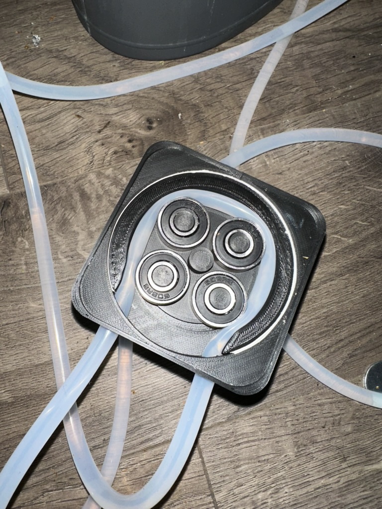
- Irrigation Pump Module (ESP32): An ESP32 controlling a stepper motor and pump to dispense water accurately.
3. Component Breakdown
A. Soil Moisture Sensing Module
- Hardware: ESP32 microcontroller, capacitive soil moisture sensor.
- Purpose: To measure the moisture content of the soil in its designated zone.
- Outputs:
rawValue: Integer ADC reading from the sensor (e.g., ~1200 for wet, ~2800 for dry, varies by sensor and soil).moisturePercent: Integer (0-100%) representing relative moisture. Calculated on the ESP32 using a linear map function with sensor-specificSENSOR_AIR_VALUE(0% reference) andSENSOR_WATER_VALUE(100% reference).sensorID: A unique string/integer to identify the sensor/zone (e.g., "ZoneA_Veg").
- Data Transmission: Periodically (e.g., every 15-60 minutes) sends data as a JSON payload via HTTP POST to the FastAPI server. Includes a timestamp.
- Calibration Caveat: The
moisturePercentis a relative index, not absolute Volumetric Water Content (VWC). Its accuracy is highly dependent on the initial two-point calibration specific to each sensor and soil type.
B. Irrigation Pump Module
- Hardware: ESP32 microcontroller, stepper motor driver (e.g., A4988), NEMA stepper motor, peristaltic or diaphragm pump head.
- Control Logic: Based on an evolution of
esp32_calibration_code.EN_PIN(D5 on ESP32): Enables/disables the motor driver (LOW = Enabled).STEP_PIN(D8 on ESP32): Each pulse advances the motor one step/microstep.DIR_PIN(D7 on ESP32): Sets the direction of rotation (HIGH for default dispensing).
- Primary Command Interface: Serial communication (115200 baud, ASCII string +
\\n).steps <numberOfMicrosteps> <totalPeriodMicroseconds>\\n: Dispenses volume by executing<numberOfMicrosteps>. Speed is set by<totalPeriodMicroseconds>(e.g., 1kHz pulse rate). This command is blocking on the Pump ESP32.motor_enable\\n: Explicitly enables the motor driver.motor_disable\\n: Explicitly disables the motor driver (sets EN_PIN HIGH).- (Optional, as per Spiral 4) May acknowledge commands with
ACK\\nor signal completion withDONE\\n.
- Critical Calibration Value:
mL_per_microstep(e.g., 0.000625 mL/microstep). This value is determined experimentally and is essential for converting a target volume in mL to the required number of motor microsteps.
C. FastAPI Server
- Purpose: Decouples sensor data production from consumption by the CCU. Provides a RESTful API for data exchange.
- Technology: Python using the FastAPI framework.
- Key Endpoints (Stable as of Spiral 4):
POST /data/soil_moisture/: Receives JSON data from soil moisture modules. Stores the latest reading persensorIDalong with a reception timestamp.GET /data/soil_moisture/latest/{sensorID}: Provides the most recent JSON data record for the specifiedsensorIDto the CCU.
D. Central Control Unit (CCU)
- Hardware Options: ESP32 (for a fully embedded solution) or a Raspberry Pi/small server (which could also host the FastAPI server).
- Core Responsibilities (as of Spiral 4):
- Data Fetching: Periodically polls the FastAPI server for the latest data from all configured
sensorIDs. - Configuration Management: Loads irrigation zone configurations from a file (e.g.,
config.jsonstored on the CCU's filesystem). - Decision Logic: For each zone, compares current
moisturePercentagainst configured thresholds, considering data freshness and validity. - Pump Command: Calculates necessary pump parameters and sends commands to the Pump ESP32 via Serial.
- Fail-Safe Implementation: Handles scenarios like stale, missing, or invalid sensor data.
- Status Indication: (Optional, as per Spiral 4) May include basic LED indicators for system status (e.g., power, watering, error).
- Data Fetching: Periodically polls the FastAPI server for the latest data from all configured
4. System Logic & Operation
A. Data Acquisition & Validation
- Soil Sensor Modules autonomously read sensor values, calculate
moisturePercent, andPOSTa JSON payload (includingsensorID,rawValue,moisturePercent, andtimestamp) to the FastAPI server. - The CCU, at a configurable interval (e.g., every 10-30 minutes), iterates through its list of configured zones.
- For each zone, the CCU makes a
GETrequest to the FastAPI server for the latest data associated with the zone'ssensorID. - The CCU validates the received data:
- Freshness: Checks the timestamp. If data is older than a defined threshold (e.g., 2-3 times the sensor's reporting interval), it's considered stale.
- Validity: Checks if
rawValueandmoisturePercentare within expected operational ranges (e.g.,0 <= moisturePercent <= 100).
B. Zone Management & Configuration
The system supports multiple distinct irrigation zones, each with its own settings. Configuration is managed via a JSON file (e.g., config.json) on the CCU, structured similar to this:
[
  {
    "zoneID": "Zone1_Vegetables",
    "sensorID": "SensorA_Veg",
    "triggerMoisturePercent": 30,
    "targetVolumeML": 500,
    "pumpPeriodMicroseconds": 1200,
    "mL_per_microstep": 0.000625
  },
  {
    "zoneID": "Zone2_Herbs",
    "sensorID": "SensorB_Herbs",
    "triggerMoisturePercent": 40,
    "targetVolumeML": 250,
    "pumpPeriodMicroseconds": 1500,
    "mL_per_microstep": 0.000625
  }
]
C. Irrigation Decision Logic (executed per zone by CCU)
For each zone:
- Fetch and validate sensor data as described above.
- IF
currentMoisturePercent<zone.triggerMoisturePercentAND data is fresh AND data is valid:- Log decision to water.
- Calculate
numberOfMicrosteps = zone.targetVolumeML / zone.mL_per_microstep. - Send
motor_enable\\ncommand to Pump ESP32. - Send
steps <calculated_numberOfMicrosteps> <zone.pumpPeriodMicroseconds>\\ncommand. - (Optional: Wait for
ACK\\norDONE\\nfrom pump, or use a timeout). - Send
motor_disable\\ncommand to Pump ESP32 (either immediately after this zone or after the entire irrigation cycle for all zones).
- ELSE (condition not met, or data invalid/stale):
- Log reason for not watering (e.g., "Moisture sufficient for Zone1", "SensorA_Veg data stale").
D. Pump Control Mechanism
The CCU translates the desired water volume into precise motor commands. The Pump ESP32 focuses solely on executing these commands, handling the low-level motor stepping and timing. The blocking nature of the steps command on the Pump ESP32 is architecturally handled by keeping the CCU as a separate, non-blocked unit.
E. Fail-Safe Behaviors (Implemented in Spiral 4)
- Stale/Missing Sensor Data: If the CCU cannot retrieve fresh data for a sensor from FastAPI after a certain number of attempts or if the latest data is too old, it will skip the irrigation cycle for that specific zone and log an error.
- Unreliable/Invalid Sensor Data: If
rawValueormoisturePercentare significantly outside calibrated/expected ranges (e.g.,moisturePercent < 0orrawValue == 0if unexpected), the CCU treats the data as invalid for that cycle, skips irrigation for the affected zone, and logs the anomaly. - (No default timed watering fallback implemented as of Spiral 4 unless explicitly added as an optional objective).
5. Communication Interfaces
A. Soil Sensor to FastAPI Server
- Protocol: HTTP
- Endpoint:
POST /data/soil_moisture/ - Method:
POST - Payload Format: JSON
- Example Payload:
{
  "sensorID": "SensorA_Veg",
  "rawValue": 1850,
  "moisturePercent": 65,
  "timestamp": "2025-05-27T18:00:00Z"
}
B. CCU to FastAPI Server
- Protocol: HTTP
- Endpoint:
GET /data/soil_moisture/latest/{sensorID}(e.g.,/data/soil_moisture/latest/SensorA_Veg) - Method:
GET - Response Format: JSON (same as POST payload) or an appropriate HTTP error code (e.g., 404 if sensor data not found).
C. CCU to Pump Module
- Protocol: Serial (UART)
- Baud Rate: 115200
- Data Format: ASCII strings, newline (
\\n) terminated. - Defined Commands:
steps <numberOfMicrosteps> <totalPeriodMicroseconds>\\n- Example:
steps 160000 1000\\n(Dispense volume equivalent to 160,000 microsteps at 1000µs per step period).
- Example:
motor_enable\\n: Activates the stepper motor driver.motor_disable\\n: Deactivates the stepper motor driver to save power and prevent motor heat/hum.- (Optional) Expected responses from Pump:
ACK\\norDONE\\n.
6. Current Project Status (End of Spiral 4)
- The system successfully monitors multiple zones using distinct soil moisture sensors.
- Irrigation for each zone is automated based on configurable thresholds (
triggerMoisturePercent) and dispense volumes (targetVolumeML) loaded from aconfig.jsonfile. - Basic fail-safe mechanisms for handling stale, missing, or clearly invalid sensor data are operational, preventing erroneous watering and logging issues.
- Pump control includes
EN_PINmanagement viamotor_enable/motor_disablecommands for better efficiency and motor lifespan. - The primary communication interfaces (HTTP for FastAPI, Serial for pump) are defined, stable, and functional.
- (Include any details on LED status indicators if implemented, e.g., "A status LED on the CCU indicates operational state: green for idle/monitoring, blue for active watering, red for system error.")
7. Code & Schematics
All source code for the Soil Moisture Sensor ESP32 firmware, Pump Control ESP32 firmware, FastAPI Server application, and the Central Control Unit logic can be found in my project repository:
- GitHub Repository:
[Link to Your GitHub Repository Here]
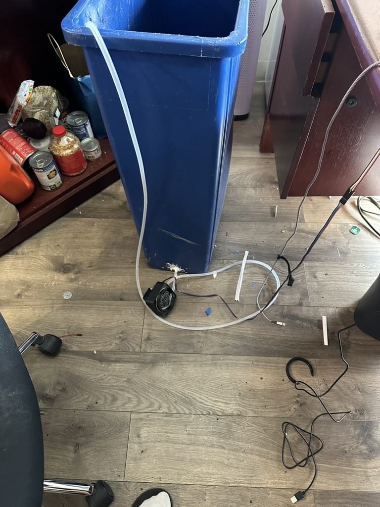
(Consider embedding a Fritzing diagram or a clear photo of your setup here.)
8. Challenges & Learnings (Examples)
- Sensor Calibration: Accurately calibrating the
SENSOR_AIR_VALUEandSENSOR_WATER_VALUEfor each capacitive soil moisture sensor in its specific soil type was critical and iterative. These values significantly impact themoisturePercentreading. - Pump Volumetric Accuracy: Precisely calibrating
mL_per_microstepfor the pump required careful experimentation and averaging over multiple trials to ensure consistent dispense volumes. - ESP32 Wi-Fi Stability: Initial challenges with ESP32 Wi-Fi reliability required implementing retry logic for HTTP requests and ensuring good network signal strength.
- Blocking Operations: The blocking nature of the pump's
stepscommand necessitated the architectural decision to have a separate CCU, preventing the entire system from freezing during dispensing. - Configuration Management: Transitioning from hardcoded parameters to a file-based configuration (
config.json) greatly improved flexibility and testability for different zones and conditions.
9. Next Steps / Future Development
Beyond the current Spiral 4 status, planned enhancements include:
- Integration of a weather forecast API to intelligently adjust watering schedules (e.g., delay watering if rain is imminent).
- Development of a simple web-based dashboard (potentially served by the FastAPI server or CCU if it's an RPi) for remote monitoring of sensor values, system status, and manual override capabilities.
- Implementing more sophisticated error detection, logging, and potentially user notifications (e.g., email alert for critical sensor failure).
- Long-term field testing to evaluate reliability and refine calibration parameters across seasons.
- Exploring alternative pump types or flow sensors for closed-loop volume control.
Vertical Linear Actuator
1. Introduction & Overview
This project is an automated vertical linear actuator designed to precisely control the height of an LED grow light panel for an indoor garden system. The primary goal is to maximize the amount of plants that the light handle and optimize light distribution. The system employs a dual NEMA 17 stepper motor configuration, controlled by an ESP32 microcontroller, allowing for an extended range of motion and fine-tuned positioning.
The development followed a spiral methodology, incrementally building and testing functionality from basic motor control to coordinated multi-axis movement.
2. System Design & Components
The actuator is designed with two stepper motors working in tandem along a single vertical axis.
2.1. Mechanical Design
Dual-Stepper Configuration:
- Motor 1 (M1 - Coarse/Main Lift): This lower motor is responsible for the primary vertical movement of the entire upper assembly. It carries the load of Motor 2, its mounting hardware, and the LED panel.
- Motor 2 (M2 - Fine/Extension Lift): Mounted on M1's moving carriage, M2 provides additional vertical travel for the LED panel itself, relative to M1's position. This allows for either an extended total range or finer adjustments within a smaller range.
Linear Motion: Both motors drive lead screws (e.g., repurposed Prusa MK3 Z-axis TR8*8 lead screws) to convert rotational motion into linear motion. The entire assembly slides along a rigid linear rail to ensure stability and smooth travel.
Payload: A sideways-mounted LED grow light panel.
Cable Management: A critical consideration due to M2 and the LED panel moving with M1. A flexible drag chain or a carefully managed service loop is necessary to protect wiring.
2.2. Electronics Hardware
- Microcontroller: ESP32-C3-DevKitM-1 – chosen for its processing power, Wi-Fi capabilities (for potential future IoT integration), and sufficient GPIO.
- Stepper Motors: 2x NEMA 17 bipolar stepper motors.
- Stepper Motor Drivers: 2x stepper motor driver modules (e.g., STSPIN820, A4988, DRV8825) capable of microstepping (configured for 1/128th microsteps for smooth motion).
- Limit Switches: 2x mechanical limit switches, used for homing M1 and M2 to their respective bottom positions. Configured as Normally Closed (NC) switches connected to GND and a GPIO pin with an internal pull-up.
- Power Supply: A DC power supply appropriately rated for the ESP32, both stepper motors (voltage and current), and the LED panel.
2.3. Software Design (Control System)
The control software is written in C++ using the Arduino framework for the ESP32.
Development Approach: A spiral development model was used to incrementally build features:
- Iteration 0-1: Basic independent motor control, then homing for M1 and position tracking.
- Iteration 2: Homing for M2, steps-per-mm calibration, mm-based position reporting, and handling inverted direction logic for one of the motors.
- Iteration 3: Software end-stops for safe travel limits, and coordinated absolute panel positioning logic.
- Iteration 4: Persisting continuous sliding
Key Features:
- Independent and coordinated control of two stepper motors.
- Precise homing routine for both axes.
- Position tracking in both steps and millimeters.
- Software-configurable steps-per-millimeter for accurate calibration.
- Software-defined travel limits (end-stops).
- Command to move the LED panel to an absolute vertical height.
- Serial command interface for control and diagnostics.
Communication: USB Serial for commands and feedback.
3. Key Software Functionality & Control
The system is controlled via serial commands sent to the ESP32.
3.1. Homing (home 1, home 2, home_all)
A critical function to establish a known reference point (zero position) for each motor.
- M1 homes first by moving physically DOWN until its bottom limit switch is triggered.
- M2 then homes by moving physically DOWN (relative to M1's carriage) until its limit switch is triggered.
- After hitting a switch, the motor backs off a small, defined distance to release the switch.
- The homed position (at the switch activation point) is defined as 0 steps for that motor. Position values increase as the motor moves physically UP.
3.2. Position Control
Direction (dir <motor> <0|1>): Sets the intended physical direction of movement (0 for UP, 1 for DOWN). The software handles any necessary inversion of the DIR pin logic for specific motors.
Relative Moves (steps <motor> <count> <period_us>): Moves the specified motor by a relative number of steps at a given step period.
Continuous Moves (speed <motor> <period_us>): Runs the specified motor continuously at a given step period until a stop command.
Position Querying:
get_pos_steps <1|2>: Returns the current position of the specified motor in microsteps from its home.get_pos_mm <1|2|all>: Returns the current position of the motor(s) in millimeters from home.
Absolute Panel Positioning (move_panel_to <target_abs_mm>): This command moves the LED panel to a specific absolute vertical height from the base of the system.
The absolute panel position is calculated as: PanelPos_mm = (M1_currentPositionSteps / M1_steps_per_mm) + (M2_currentPositionSteps / M2_steps_per_mm)
The control logic determines the necessary movements for M1 and M2 to achieve this target, respecting individual motor software limits. Motors are moved sequentially.
Panel Position Query (get_panel_pos_mm): (Should be get_panel_pos_mm or similar, if get_pos_mm all doesn't give the combined value). This command would report the calculated absolute height of the LED panel.
3.3. Calibration & Safety
Steps per Millimeter (set_steps_per_mm <motor> <value>): Allows calibration of how many microsteps correspond to 1mm of linear travel for each motor. This is crucial for accurate positioning in real-world units. Depends on lead screw pitch and microstepping settings.
Example Calculation: For a TR8*8 lead screw (8mm travel per revolution) and a 1.8° NEMA 17 motor (200 full steps/revolution) with 1/128 microstepping: Steps_per_mm = (200 full_steps/rev * 128 microsteps/full_step) / 8 mm/rev = 3200 microsteps/mm
Software End-Stops (Iteration 3): Constants like M1_MAX_TRAVEL_MM and M2_MAX_TRAVEL_MM define the maximum permissible travel for each motor from its home position. Movement commands check against these limits (if the motor is homed) to prevent over-travel and potential mechanical damage.
3.4. Motion Smoothing (Iteration 4)
To prevent missed steps, reduce mechanical stress, and achieve smoother operation, especially when moving the significant mass of M2 and the LED panel, acceleration and deceleration (ramping) are implemented. This involves gradually changing the step period at the beginning and end of moves, rather than instantly starting/stopping at full speed.
(Describe your chosen method briefly: e.g., Linear Ramp or AccelStepper library integration).
4. Challenges & Learning
(This is a section for you to personalize heavily! Here are some potential points you might have encountered or learned from):
- Mechanical Alignment: Ensuring the linear rail, lead screws, and motor shafts are perfectly aligned to prevent binding and ensure smooth motion.
- Cable Management: Designing a robust solution for the moving cables to M2 and the LED panel to prevent snagging and wear.
- Software Complexity: Managing the states of two motors, their homing sequences, coordinate systems, and direction logic requires careful planning and debugging.
- Motor Tuning: Finding the right balance for stepper motor current, speed, and acceleration to achieve reliable movement without overheating or stalling.
- Limit Switch Precision: Ensuring limit switches trigger consistently and that the back-off distance is appropriate.
- Debugging Serial Communication: Effectively using serial prints for debugging state variables and command parsing.
- Iterative Development: Experiencing the benefits of the spiral development model by building and testing features incrementally.
5. Future Work & Potential Improvements
Advanced Coordinated Motion: Implement more sophisticated algorithms for distributing movement between M1 and M2 when move_panel_to is called (e.g., to minimize wear, maximize speed, or keep M2 in a preferred part of its range). Potentially simultaneous movement of M1 and M2 if using a library like AccelStepper.
- Sensor Integration:Add a plant height sensor (e.g., ultrasonic, ToF LiDAR) to enable fully autonomous height adjustment based on actual plant growth.Temperature/humidity sensors for environmental monitoring.
- User Interface: Develop a web interface (using the ESP32's Wi-Fi) or a dedicated physical interface (buttons, LCD) for easier control instead of relying solely on serial commands.
- Persistent Settings: Store calibration values (steps_per_mm, max travel) in the ESP32's non-volatile memory (EEPROM or LittleFS) so they persist across power cycles.
- Error Detection & Recovery: More robust error handling (e.g., detecting stalls if using TMC drivers with StallGuard, or if homing fails repeatedly).
6. Code & Visuals
The complete Arduino sketch for the ESP32 controller can be found here:[Link to your Git repository or code file]
(Embed key code snippets here if desired, e.g., the homeMotor function or the move_panel_to logic).
    // Key code snippets can be embedded here.
    // For example:
    // void homeMotor(int motorNum) {
    //   // ... homing logic ...
    // }
Visuals
Irrigation System