Wireless Communication with ESP8266
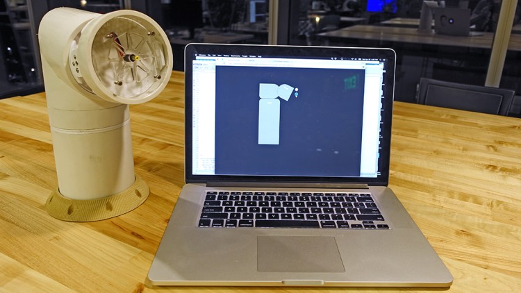
Demo
Here are the steps that I took to get my robot up and running with ESP8266
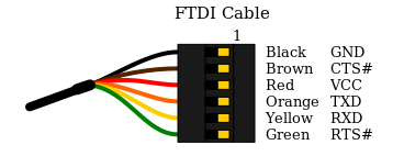
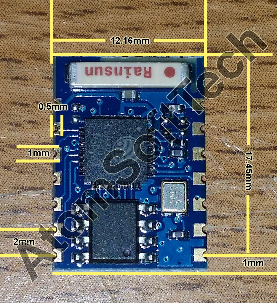
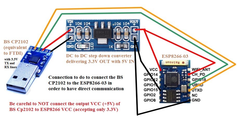
- Connect ESP8266-03 to FTDI or an Arduino to talk to it via Serial at 9600 Bud Rate using AT command
Tip: Make sure you use good 3.3V power Source - Making ESP8266 as an access point, send get request with Google Chrome
Tip: Get IP with AT command
Get request looks like this http://192.168.4.1/?s=100
Keep it short
Will not work in Safari if you don’t have the right HTML header - Have ESP8266 connected to an WiFi router
Note: This is slower than WiFi access point mode - Blink LED then Add Servo
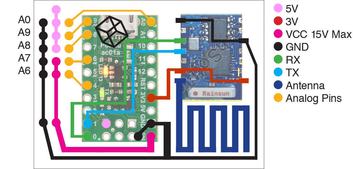
Note: Software Serial will cause servo twitching, it’s best to just use hardware serial. Hardware serial in arduino code is Serial1.begin instead of Serial.begin() if you are using the arduino IDE - Making a ESP8266 and A-Star / Arduino Leo combine board
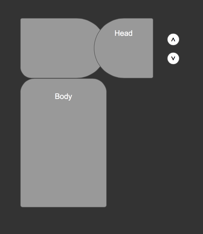
I used inDesign, overlay the lines right on top of the image - Design a Web Interface to control the Robot
I used Jquery library to do the get request and animation. - Try TCP and UDP
Pending …
Download All ESP8266 related sample Code
Setup ESP8266 via serial with AT Command
Bud rate forESP8266-03 is 9600
You can use the Arduino IDE to motor the serial. You can use hardware serial or software serial. It might be easier to get started with FTDI, but I started with Software serial using Arduino’s Pin 10 and Pin 11.
Note: Use Serial1.begin()l if you are using Arduino LEO’s D1 & D0 as hardware serial. For everything else use Serial.begin()…
There are no spaces between the Command and the Parameters.
Source: https://nurdspace.nl/ESP8266#AT_Commands
| Commands | Description | Set/Execute | Parameters |
|---|---|---|---|
| AT+RST | restart the module | – | – |
| AT+CWMODE | wifi mode | AT+CWMODE=<mode> | 1= Sta, 2= AP, 3=both |
| AT+CWJAP | join the AP | AT+ CWJAP =<ssid>,< pwd > | ssid = ssid, pwd = wifi password |
| AT+CWLAP | list the AP | AT+CWLAP | |
| AT+CWQAP | quit the AP | AT+CWQAP | |
| AT+ CWSAP | set the parameters of AP | AT+ CWSAP= <ssid>,<pwd>,<chl>, <ecn> | ssid, pwd, chl = channel, ecn = encryption |
| AT+ CIPSTATUS | get the connection status | AT+ CIPSTATUS | |
| AT+CIPSTART | set up TCP or UDP connection | 1)single connection (+CIPMUX=0) AT+CIPSTART= <type>,<addr>,<port>; 2) multiple connection (+CIPMUX=1) AT+CIPSTART= <id><type>,<addr>, <port> | id = 0-4, type = TCP/UDP, addr = IP address, port= port |
| AT+CIPSEND | send data | 1)single connection(+CIPMUX=0) AT+CIPSEND=<length>; 2) multiple connection (+CIPMUX=1) AT+CIPSEND= <id>,<length> | |
| AT+CIPCLOSE | close TCP or UDP connection | AT+CIPCLOSE=<id> or AT+CIPCLOSE | |
| AT+CIFSR | Get IP address | AT+CIFSR | |
| AT+ CIPMUX | set mutiple connection | AT+ CIPMUX=<mode> | 0 for single connection 1 for mutiple connection |
| AT+ CIPSERVER | set as server | AT+ CIPSERVER= <mode>[,<port> ] | mode 0 to close server mode, mode 1 to open; port = port |
| +IPD | received data |
Running a WebServer
AT+CIPMUX=1
AT+CIPSERVER=1,80
From this step, I get the IP address for the chip and started to play with the URL get request
http://192.168.4.1/?p=34&s=1
7&s=1 HTTP/1.1
Host: 192.168.4.1
Connection: kAT+CIPSEND=1,1
> 8
SEND OK
AT+CIPCLOSE=1

Link

+IPD,3,329:GET /favicon.ico HTTP/1.1
Host: 192.168.4.1
Connection: keep-alive
User-Agent: Mozilla/5.0 (Macintosh; Intel Mac OS X 10_10_3) AppleWebKit/537.36 (KHTML, like Gecko) Chrome/42.0.2311.90 Safari/537.36
Accept: */*
Referer: http://192.168.4.1/?p=87&s=1
Accept-Encoding: gzip, deflate, sdch
Accept-Language: en-US,en;q=0.8


OK

OK
Control LED
I based my sketch on the following URL
http://allaboutee.com/2015/01/02/esp8266-arduino-led-control-from-webpage/
#define DEBUG false  // turn debug message on or off in serial

void setup()
{
Serial1.begin(9600);  // using serial 1 if you are using arduino LEO
Serial.begin(9600);

while (!Serial1) {
; // wait for serial port to connect. Needed for Leonardo only
}

delay(2000);

pinMode(13,OUTPUT);
digitalWrite(13,LOW);

sendData("AT+RST\r\n",2000,DEBUG); // reset module
sendData("AT+CWMODE=2\r\n",1000,DEBUG); // configure as access point
sendData("AT+CIFSR\r\n",1000,DEBUG); // get ip address //192.168.4.1
sendData("AT+CIPMUX=1\r\n",1000,DEBUG); // configure for multiple connections
sendData("AT+CIPSERVER=1,80\r\n",1000,DEBUG); // turn on server on port 80
}

void loop()
{
if(Serial1.available()) // check if the esp is sending a message
{

if(Serial1.find("+IPD,"))
{
delay(1000); // wait for the serial buffer to fill up (read all the serial data)
// get the connection id so that we can then disconnect
int connectionId = Serial1.read()-48; // subtract 48 because the read() function returns
// the ASCII decimal value and 0 (the first decimal number) starts at 48

// on your browser type http://192.168.4.1/?pin=13

Serial1.find("pin="); // advance cursor to "pin="

// get 3 digits
int pinNumber = (Serial1.read()-48)*100; //
pinNumber += (Serial1.read()-48)*10; // get first number i.e. if the pin 13 then the 1st number is 1, then multiply to get 10
pinNumber += (Serial1.read()-48); // get second number, i.e. if the pin number is 13 then the 2nd number is 3, then add to the first number

digitalWrite(pinNumber, !digitalRead(pinNumber)); // toggle pin

// generate web page
String webpage = String(pinNumber);
String cipSend = "AT+CIPSEND=";
cipSend += connectionId;
cipSend += ",";
cipSend +=webpage.length();
cipSend +="\r\n";
sendData(cipSend,1000,DEBUG);
sendData(webpage,1000,DEBUG);

// make close command
String closeCommand = "AT+CIPCLOSE=";
closeCommand+=connectionId; // append connection id
closeCommand+="\r\n";

sendData(closeCommand,1000,DEBUG); // close connection
}
}
}

/*
* Name: sendData
* Description: Function used to send data to ESP8266.
* Params: command - the data/command to send; timeout - the time to wait for a response; debug - print to Serial window?(true = yes, false = no)
* Returns: The response from the esp8266 (if there is a reponse)
*/
String sendData(String command, const int timeout, boolean debug)
{
String response = "";

Serial1.print(command); // send the read character to the esp8266

long int time = millis();

while( (time+timeout) > millis())
{
while(Serial1.available())
{

// The esp has data so display its output to the serial window
char c = Serial1.read(); // read the next character.
response+=c;
}
}

if(debug)
{
Serial.print(response);
}

return response;
}
Control Servo
I changed the code to control a servo by passing in servo position in the URL request.
The problem with Arduino Software Serial library is that the servo library uses the arduino’s Timer 1. The software serial library disables interrupts during transmit or receive operations which then prevent the timer interruts for the servo library triggering.
I had to change my board design to use Hardware Serial.
The Code
#define DEBUG false


#include
Servo servoBase1;  // create servo object to control a servo
Servo servoBase2;  // create servo object to control a servo
int pre_pos = 90;
int pos = 90;
int serAng=90;

void setup()
{
  Serial1.begin(9600);

  //pinMode(13,OUTPUT);
  //digitalWrite(13,LOW);

  sendData("AT+RST\r\n",500,DEBUG); // reset module
  sendData("AT+CWMODE=2\r\n",500,DEBUG); // configure as access point
  sendData("AT+CIFSR\r\n",500,DEBUG); // get ip address
  sendData("AT+CIPMUX=1\r\n",500,DEBUG); // configure for multiple connections
  sendData("AT+CIPSERVER=1,80\r\n",500,DEBUG); // turn on server on port 80

           delay(1000);

  servoBase1.attach(A6);
  servoBase2.attach(A7);
           delay(100);

 servoBase1.write(90);
 servoBase2.write(90);


}

void loop()
{
  if(Serial1.available()) // check if the esp is sending a message
  {


    if(Serial1.find("+IPD,"))
    {
     delay(200); // wait for the serial buffer to fill up (read all the serial data)
     // get the connection id so that we can then disconnect
     int connectionId = Serial1.read()-48; // subtract 48 because the read() function returns
                                           // the ASCII decimal value and 0 (the first decimal number) starts at 48

      // on your browser type http://192.168.4.1/?s=090

     Serial1.find("s="); // advance cursor to "pin="

     // get 3 digits
     serAng = (Serial1.read()-48)*100; //
     serAng += (Serial1.read()-48)*10; // get first number i.e. if the pin 13 then the 1st number is 1, then multiply to get 10
     serAng += (Serial1.read()-48); // get second number, i.e. if the pin number is 13 then the 2nd number is 3, then add to the first number

     //digitalWrite(serAng, !digitalRead(serAng)); // toggle pin
        // servoBase1.write(serAng);


     // generate web page
     String webpage = String(serAng);
     String cipSend = "AT+CIPSEND=";
     cipSend += connectionId;
     cipSend += ",";
     cipSend +=webpage.length();
     cipSend +="\r\n";
     sendData(cipSend,500,DEBUG);
     delay(20);
     sendData(webpage,500,DEBUG);

     // make close command
     String closeCommand = "AT+CIPCLOSE=";
     closeCommand+=connectionId; // append connection id
     closeCommand+="\r\n";

     sendData(closeCommand,500,DEBUG); // close connection


    }
  }


         if (pre_pos<serAng){
                 for(pos = pre_pos; pos <= serAng; pos += 1) // goes from 0 degrees to 180 degrees                    {                                  // in steps of 1 degree                      servoBase1.write(180-pos);                      servoBase2.write(pos);                     delay(20);                       // waits 15ms for the servo to reach the position                    }                      }          else {               for(pos = pre_pos; pos>=serAng; pos-=1)     // goes from 180 degrees to 0 degrees
              {
                servoBase1.write(180-pos);
                servoBase2.write(pos);
                delay(20);
              }
         }


          pre_pos=serAng;


}

/*
* Name: sendData
* Description: Function used to send data to ESP8266.
* Params: command - the data/command to send; timeout - the time to wait for a response; debug - print to Serial window?(true = yes, false = no)
* Returns: The response from the esp8266 (if there is a reponse)
*/
String sendData(String command, const int timeout, boolean debug)
{
    String response = "";

    Serial1.print(command); // send the read character to the esp8266

    long int time = millis();

    while( (time+timeout) > millis())
    {
      while(Serial1.available())
      {

        // The esp has data so display its output to the serial window
        char c = Serial1.read(); // read the next character.
        response+=c;
      }
    }

    if(debug)
    {
      Serial.print(response);
    }

    return response;
}
External Reference
http://allaboutee.com/2014/12/30/esp8266-and-arduino-webserver/
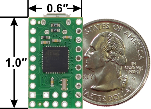
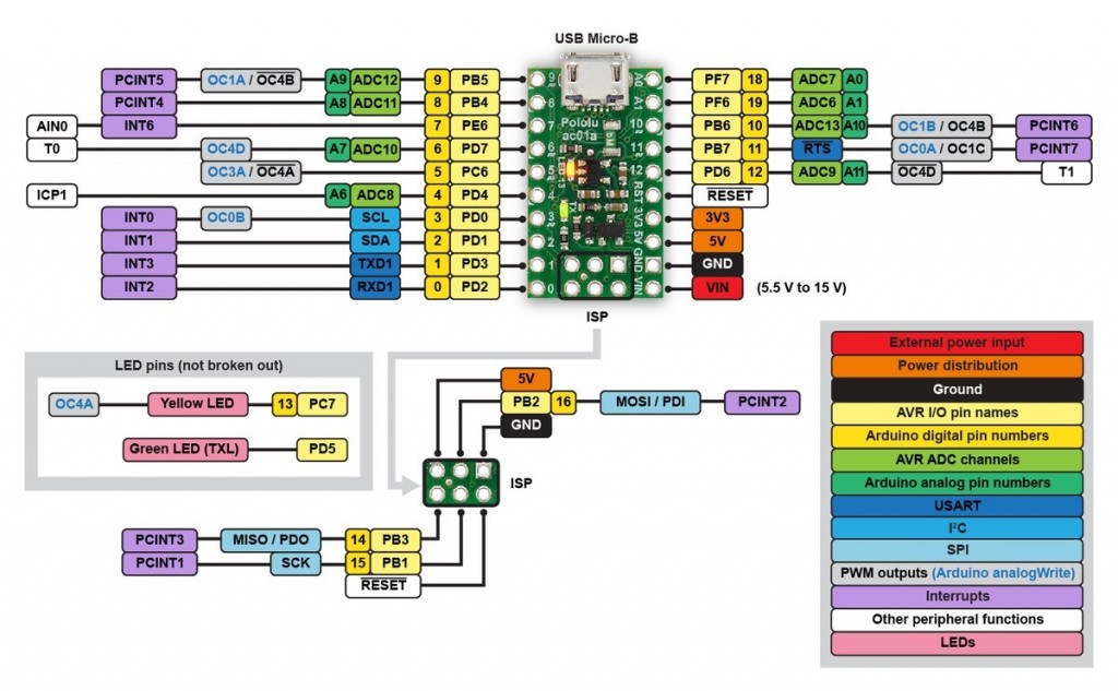
A-STAR / ARDUINO LEO’S Serial
There is now a second serial port. The primary port is built into the USB interface and the Tx/Rx LEDs are attached to it. The secondary port is located at pins D0 & D1. This port does not have any LEDs attached.
To use the primary serial port, use the class Serial as usual. For the secondary port, a new serial class called Serial1 has been created. You use it the same way as the Serial class.
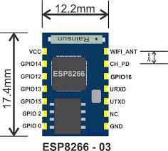
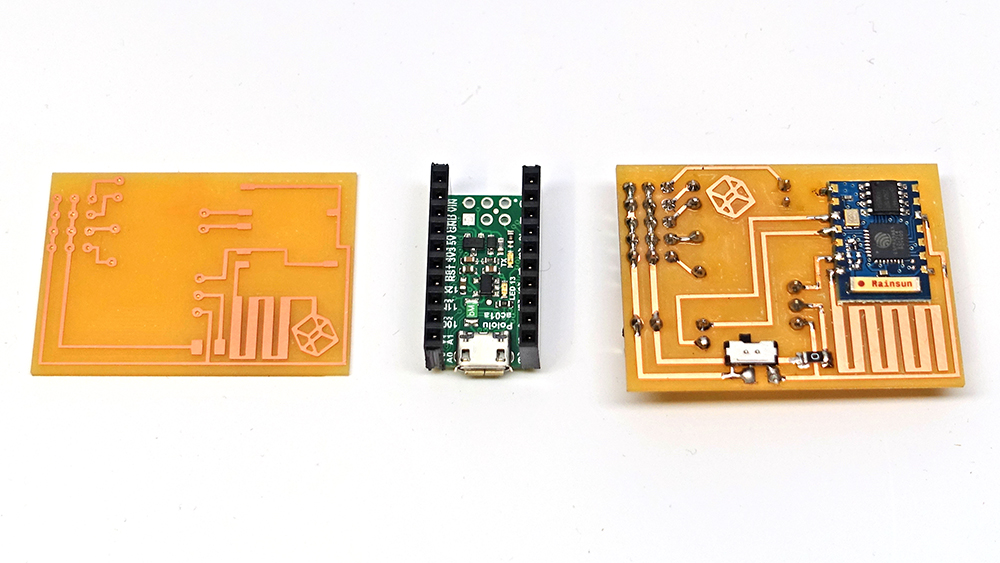
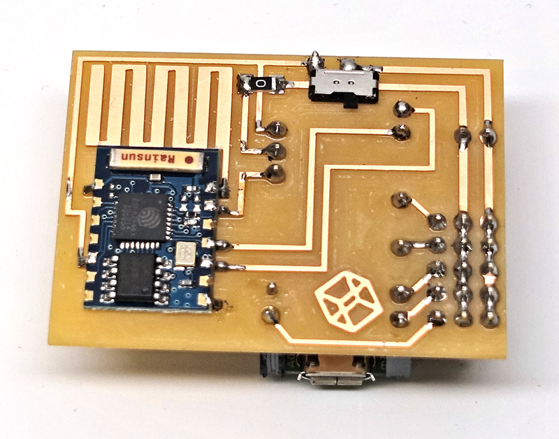
Making A-Star ESP8266 Combo board
Since there aren’t any ESP8266 template for Eagle, I end up using inDesign to create my traces. It works much better than Eagle in my case.
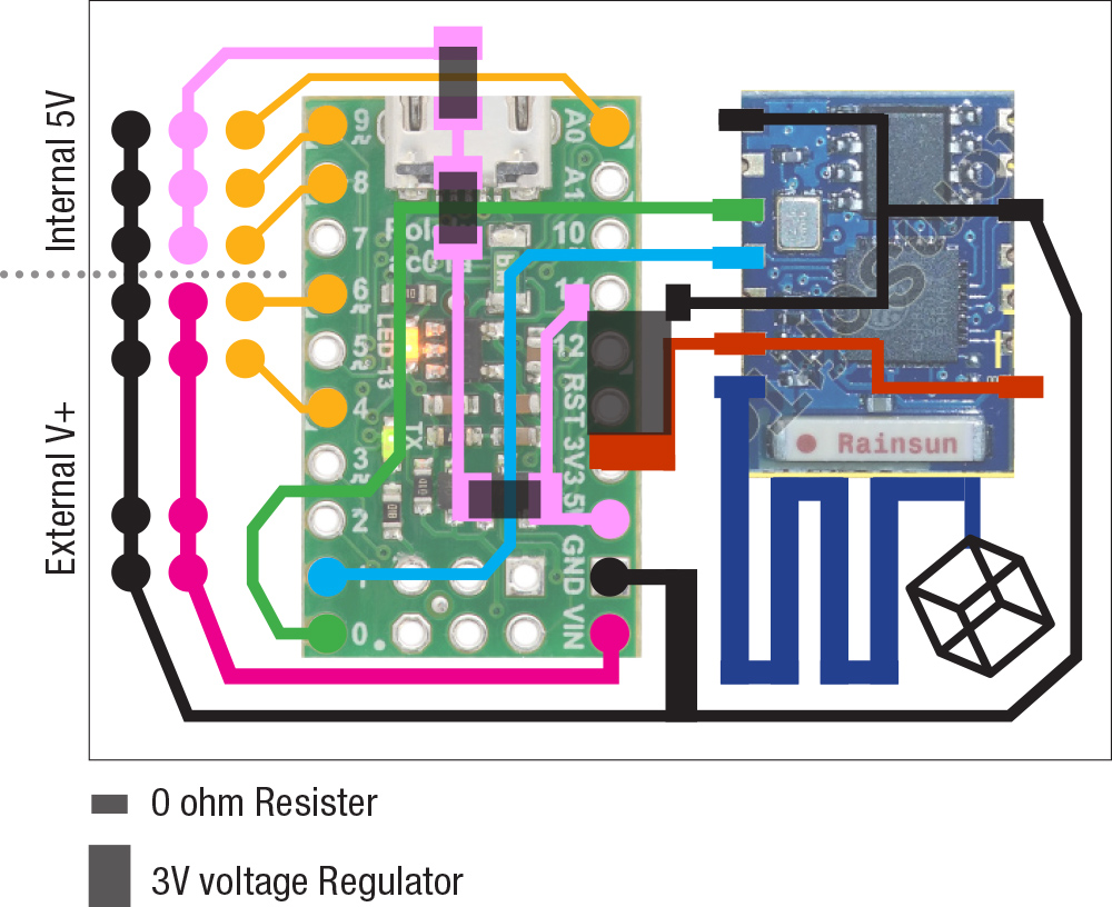
Important: 3V on board power worked for me for a little while, but for some reason it stops working. It starts to draw a lot of power cause the board to “brown” out. I later added a voltage regulator and it seems to be working okay.
Board Files (inDesign + ESP)
In this New version, I added voltage regulator, the A-start internal 3V voltage regulator sometimes isn’t enough and cause the board to brown out.
Web Control Interface
I wrote a quick and dirty web interface to control the robot. The idea is that eventually I can control all parts of the robot with Wifi. I am still not sure if I will be using ESP 8266 for my final project but some kind of wireless communication is required.