<-- HTMSTMAA
This week I wanted to explore worm gears.
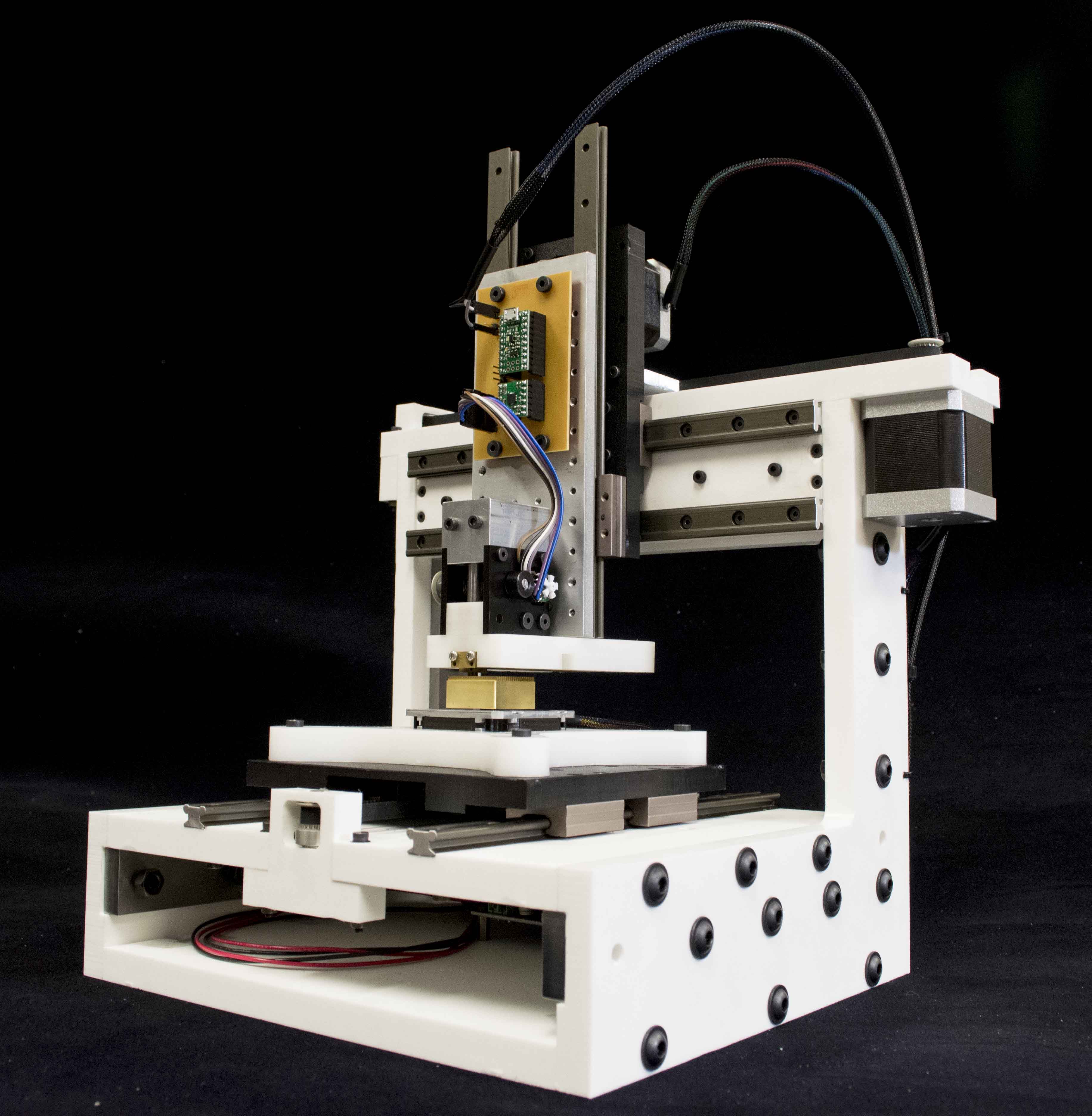
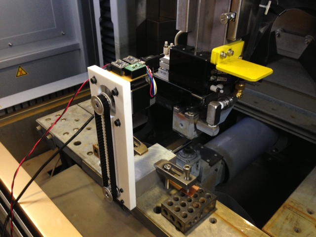
I'm working on an automated assembly machine (which I call the stapler assembler). The machine positions a part "stapler" in 4-axes (x,y,z,theta) and then deposits a part. The current mechanism consists of a rack and pinion driven by a geared DC motor througha a timing belt. While the mechanism works, it's not as consistent as it should be. Rather than making incremental improvements to it I decided this week I'd redesign it completely, incorporating all the knowledge I gained from the first prototype. Here's the previous rack and pinion design:
I wanted to the new design to be much more compact so that multiple staplers could be positioned next to eachother in a small footprint. Worm gears serve this purpose really well because everything can be inline with the rack. Worm gears also generate a huge amount of mechanical advantage in a very small package.
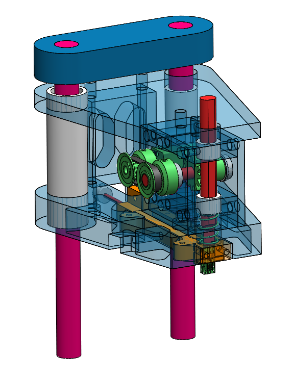
The new design uses the same motor and many of the same parts. Here it is in cross-section:
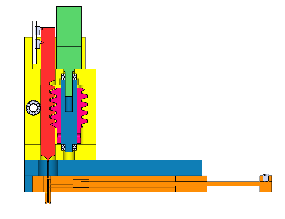
It incorporates limit switches, kinematic alignment features for the stapler cartridge, and a custom wire-edm machined rack/piston.
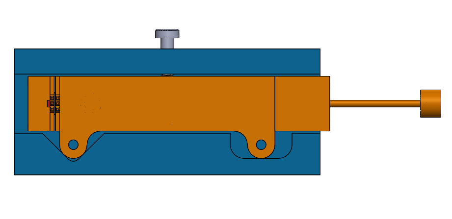
And here's how it works...
Next step... Making it.
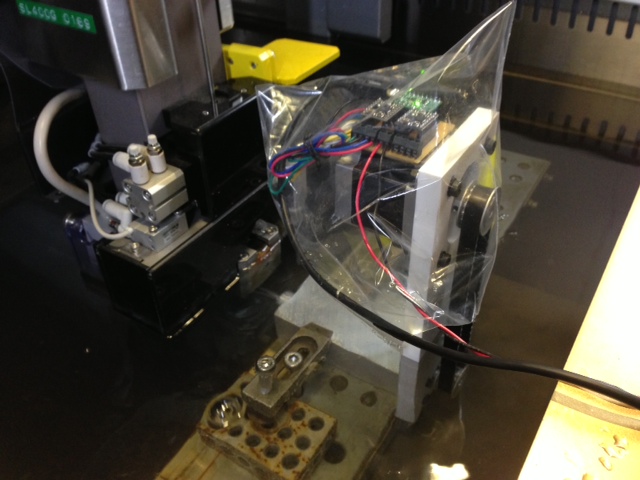
This week Sam and I also played with adding a rotary axis to our Wire-EDM. In the spirit of "gestural design," we wipped up the hardware in an evening, using a NEMA23 motor we had laying around to control the rotation of a shaft.
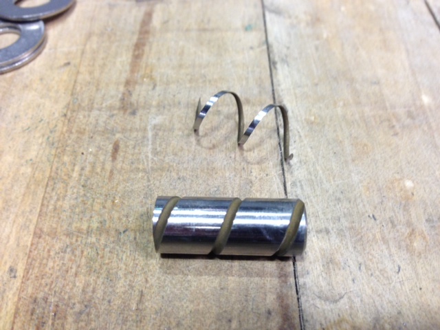
By slowly rotating the shaft while the EDM burns in a linear motion, we can create complex helical cuts like this:
Eventually we're going to hack into the machine control by using a webcam and open-cv to recognize the numbers in the DRO. This will enable us to integrate the motion of the rotary axis with movement of the other axes.
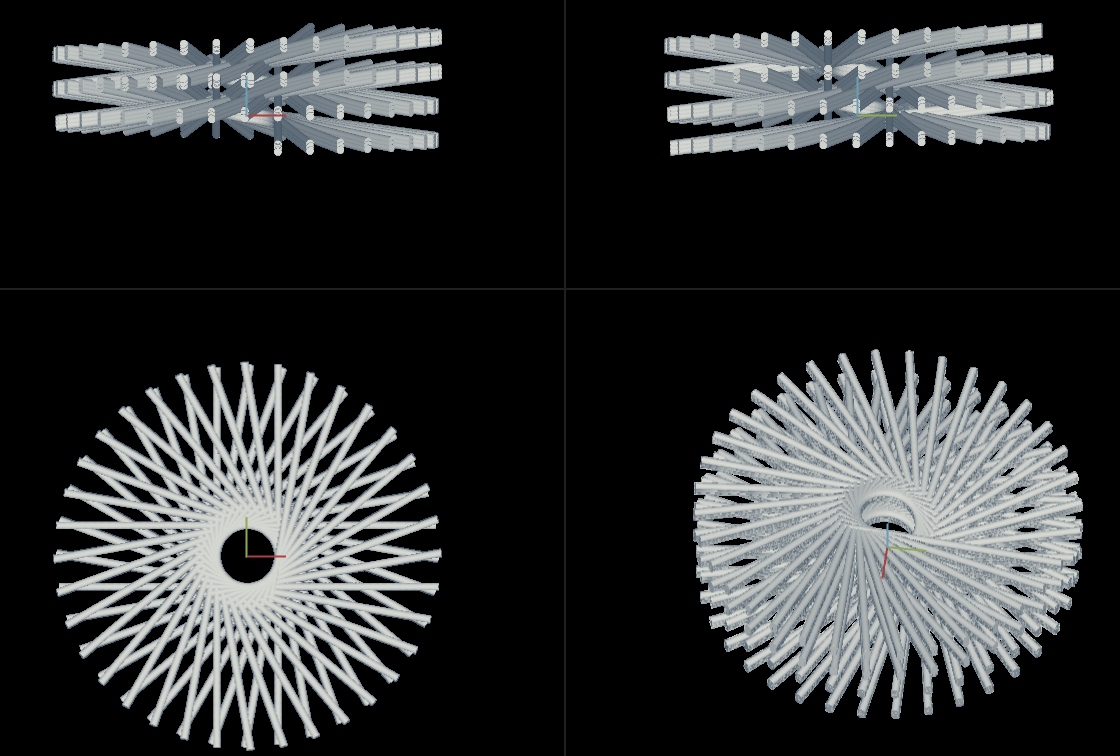
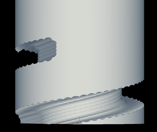
Doing CAD/CAM for this kind of machining strategy is a little tricky. None of the standard CAM packages come equipped for this kind of "turn and burn" operation. I decided to use Antimony to try to visualize the possible cuts. To do this, I simply make a cylinder that represents the wire, sweep it around the workpiece, and do a boolean operation to substract it from the starting cylinder. Here is a visualization of the wire being swept around the cylindrical workpiece.
and the resulting geometries...
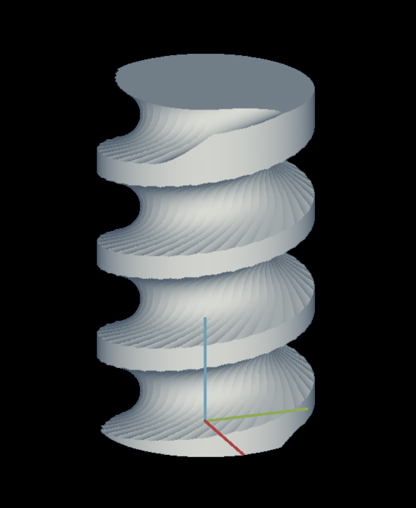
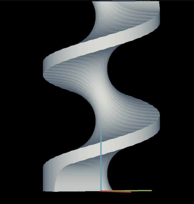
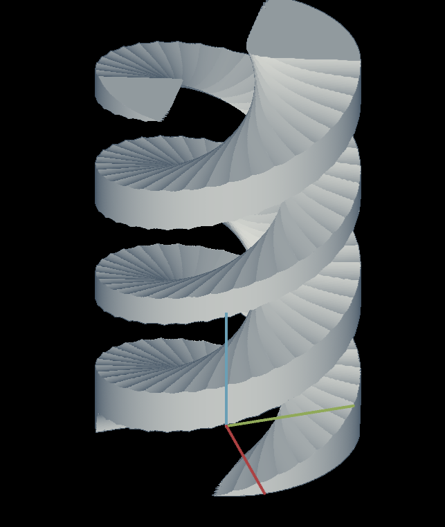
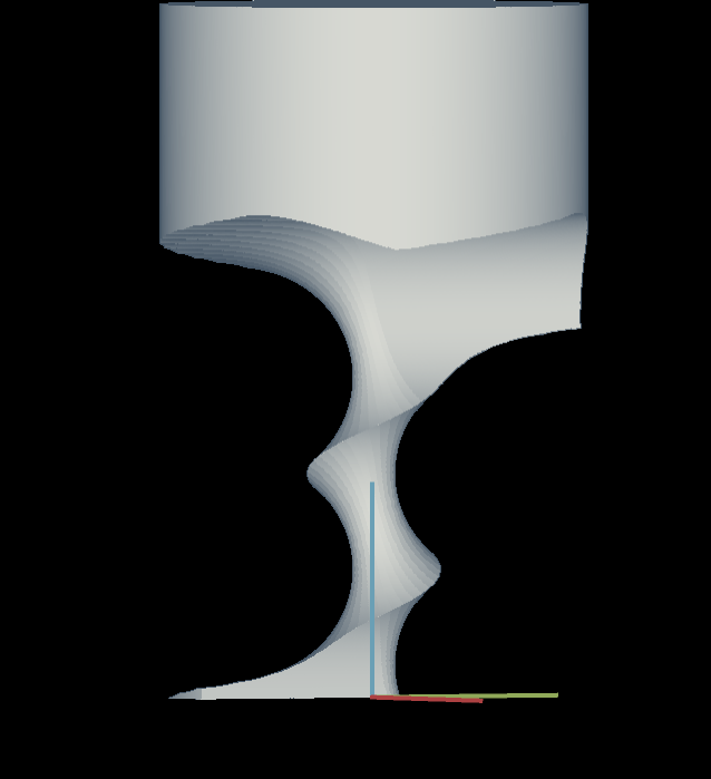
The trapezoidal tooth of the worm gear can be approximated by sweeping the wire multiple times in different locations.
Here is the latest design file.