<-- HTMSTMAA
This week I built the mechanism that I had designed last week.
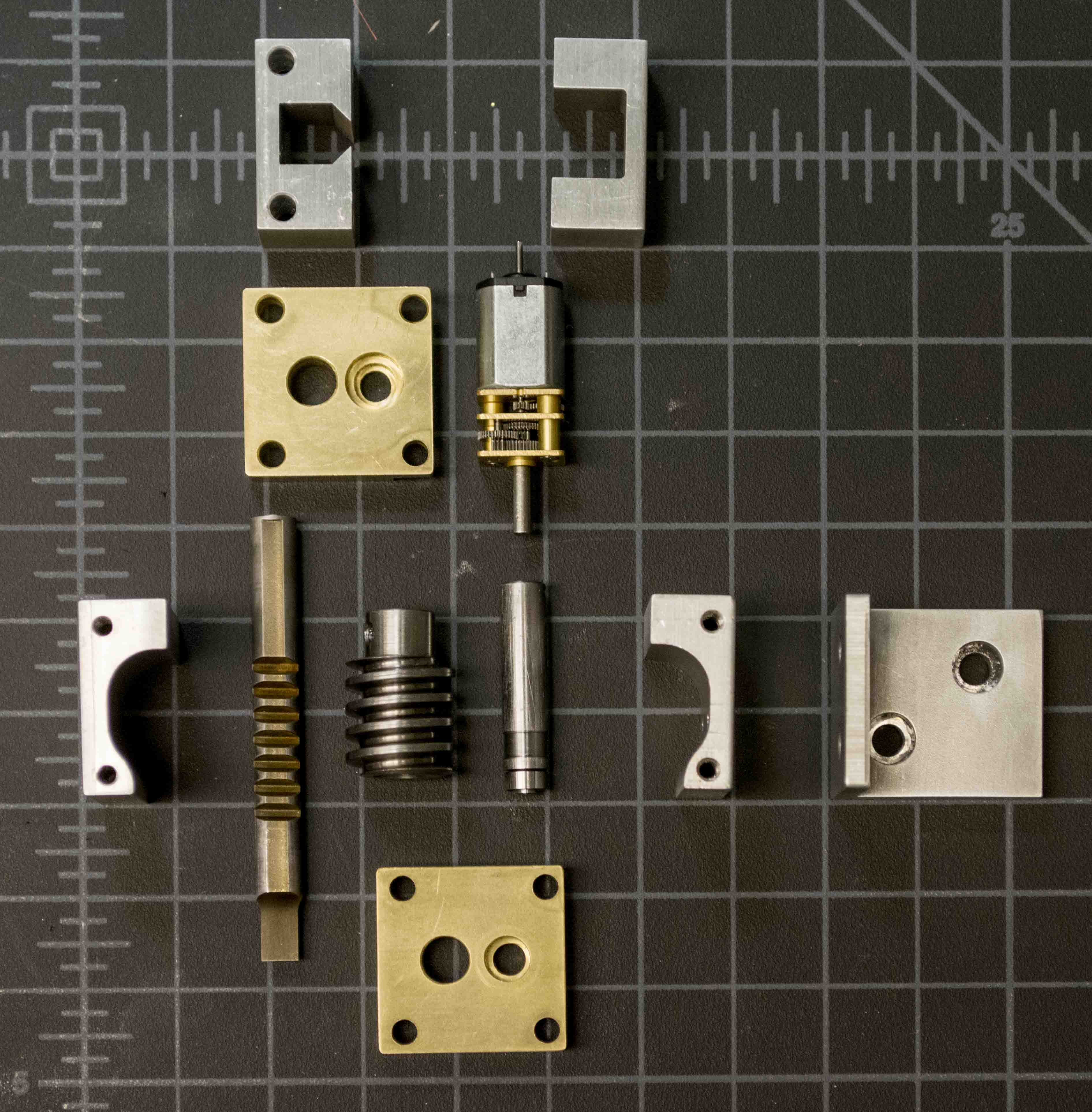
It was a lot of machining (there are 10 custom machined parts not including the actual stapler) but it all came together quite nicely. The parts are made using a combination of wire-edm'ing and manual bridgeport machining.
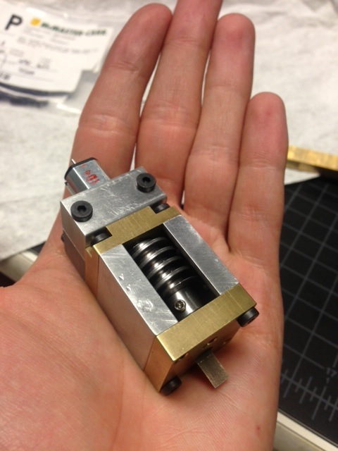
It bolts directly to the assembler and (critically) is small enough that two can be attached right next to eachother. This allows the assembly of multi-material structures.
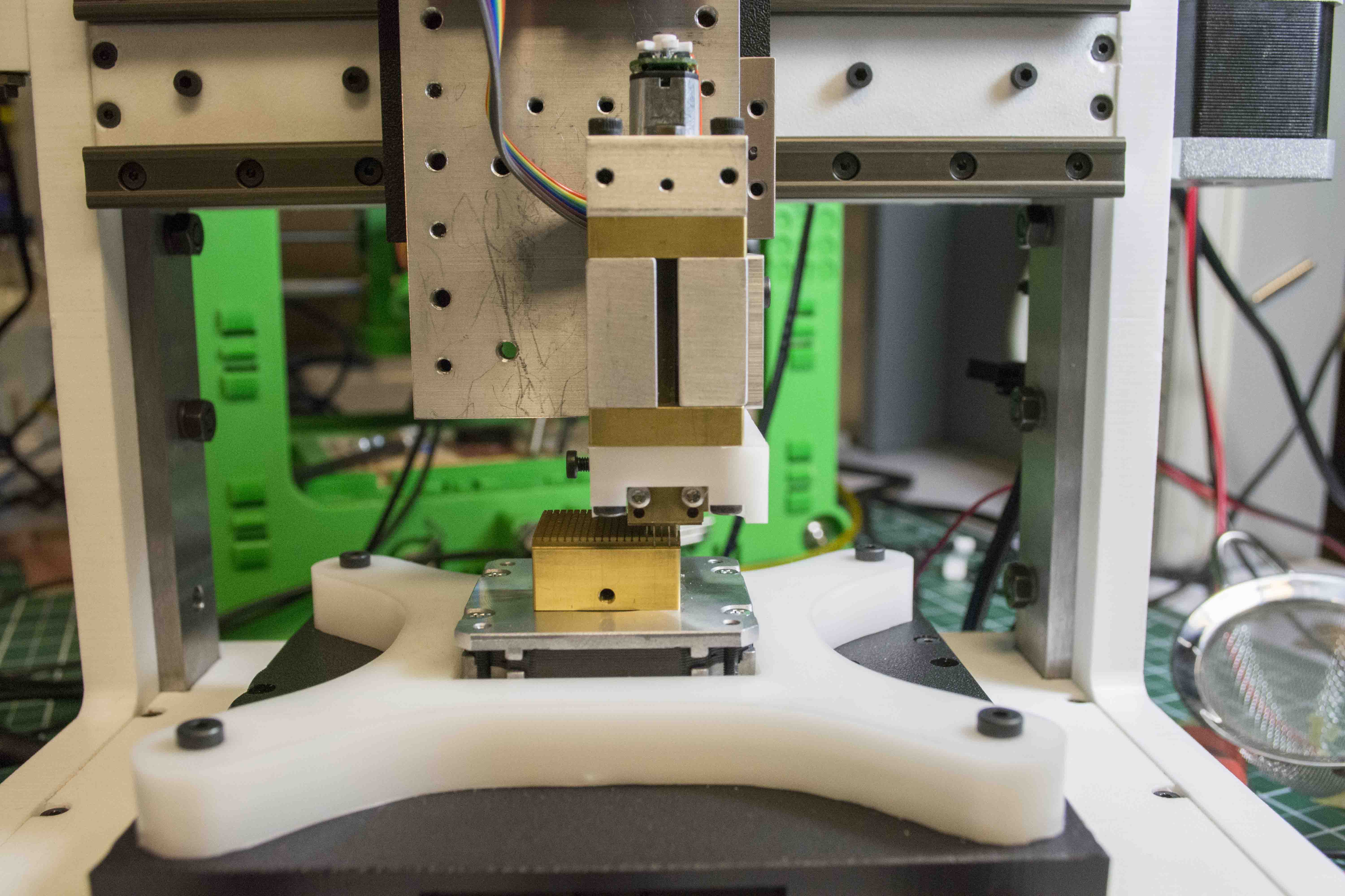
The motor is a 100:1 micro metal gear motor from Pololu. It is driven using an atmega32u4 (A-Star Micro) and DRV8801 motor driver. The microcontroller is configured to listen to a pin change sent from the TinyG that the controls the assembler. This pin change is triggered whenever an M4 or M5 g-code is passed to the TinyG from the computer. These M-codes usually correspond to selecting the spindle's direction of rotation but in this case have been mapped to move the stapler mechanism up and down.
The design originally incorporated limit switches to detect when the mechanism had finished raising or lowering but I ran out of time to incorporate those. In lieu of limit switches I use an optical encoder on the motor shaft (pre-gearing) which gives roughly 2000 counts per revolution. The only catch here is that since it is a relative encoder (with no absolute index) it must start in the same position in order to know where it is. I do this simply by driving the motor to an extremal limit (while limiting the current) and zero its position there.
To control the motor I implemented a quick and dirty PI current/torque control loop. This allows me to run the motor hard without worrying about it burning up.
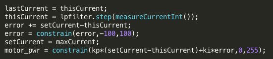
The code gets a measurement of the current from the motor driver and passes it through a low pass filter (with a 2.5Hz break) to smooth out the reading. A proportional term is then applied to the difference between actual and desired current. Additionally, an integral term is needed (largely to account for the deadband in the motor) which is applied to the sum of the errors for all time.
and it works!
This week I also thought about a component needed for a desktop wire-edm (which I'm pitching for my final project): the wire feed and tensioning mechansim.
Fancy machines (like out Sodick) have complex wire feedpaths that look like this:
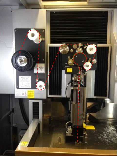
But I wanted to start more simply with the idea of using two motors to control both speed and tension of the wire.
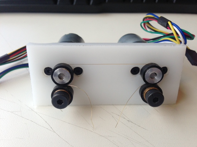
All I got up to this week was designing the circuit board and what's pictured above but in the coming weeks I'll experiment with ways to electronically control the speed and tension of the wire.