<-- HTMSTMAA
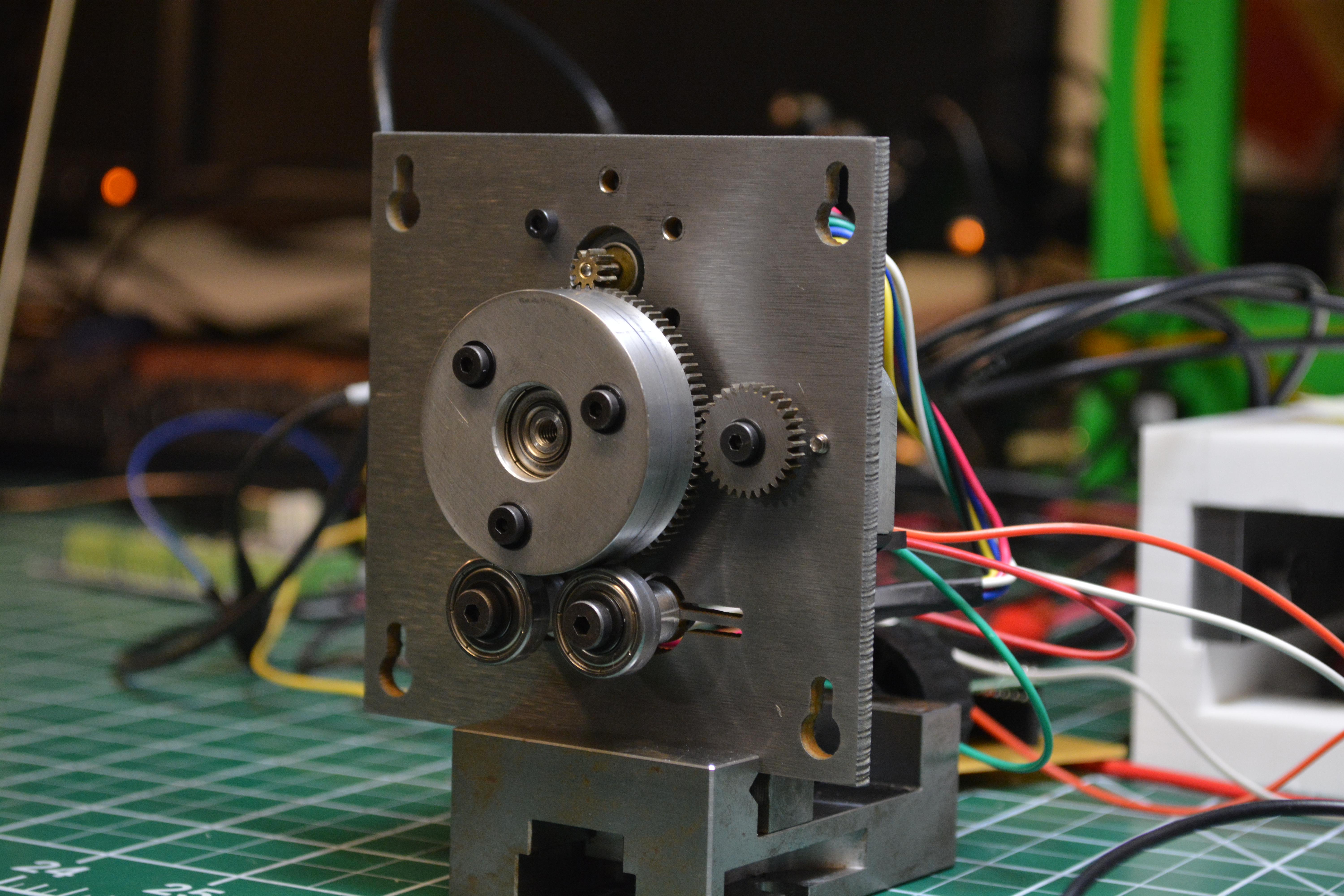
This week I made the wire feed and tensioning mechansim for my desktop wire-edm.
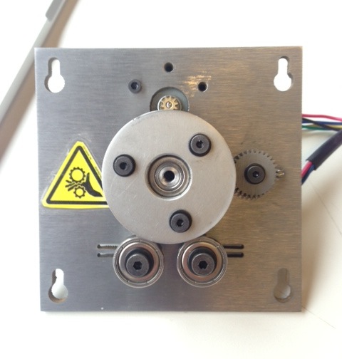
The design evolved a little bit from last week. Most notably, I added a peripheral gear to interface with an external high-resolution encoder. The encoder has selectable resolution up to 2048 counts per revolution.
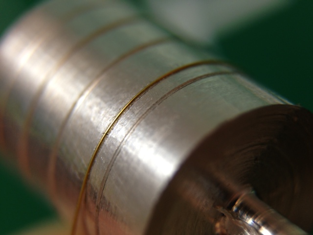
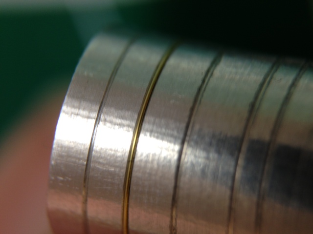
The main capstan includes a small 60-degree V-groove to hold the wire. I determined the optimal size of this experimentally by cutting a number of grooves at various depths and selecting one that provided good encapsulation while still leaving the wire raised from the capstan.
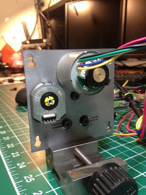
To control it, I'm using the same control board I made last week. At first I came across a problem where the encoder was sending too many pulses that the atemga spent all its time servicing interrupts and froze up. I streamlined my interrupt code and replaced all of the terribly slow digitalRead() calls with direct port manipulation but still had the problem.
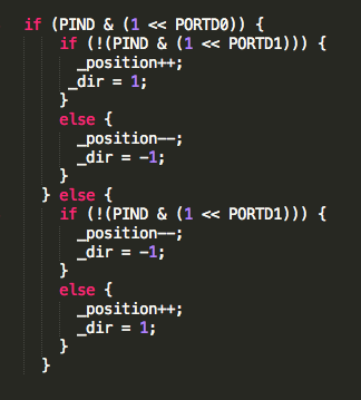
By trial and error, I found the microcontroller stopped responding if the encoder pulsed more than 32kHz. Looking around online, I found it's likely possible to get this up to 127kHz with some clever coding. By my calculations though, that still wouldn't be sufficient (I estimate the max fequency I might see is 128kHz). So, I simply had to adjust the DIP switch in the encoder to change from 2048cpr to 512cpr.
It works... Here is it running with a sinusoidal position command and resisting force I apply to it (using a basic PID scheme):
But it turns out this is a very bad thing that I'm doing here. Gears and fingers in close proximity don't often lead to nice things. So after it took a bite out of my finger I decided I had to gave it an exposed machinery hazard label...
Inspired by the difficulties we had in interfacing DC motors with a TinyG CNC controller that's geared towards stepper motors, I programmed a microcontroller to read in step and direction inputs and do closed loop PID position control to the desired position. It works great...
I suspect this might be an application that warrants something more complicated than PID control. When the motor is stopped and just needs to hold position, the gains should be dialed up such that it becomes hard to move. However, those same gains will lead to movement that's very harsh and grindy since it oscillates slightly at every step. One method of compensating for this is to do PID gain scheduling where you tune the PID parameters based on the present position/velocity but this can also lead to instabilities because velocity is not measured directly (it's derived from position).
The code is here.