First bench top prototype for heating material.. DEMO
Link to PLC used for testing. This was a pretty big pain in the ass to "program." I was initially interested in using this because it has some safety elements, but I spent so long pushing little buttons I'm probably never gonna use it again. The user interface sucks. I would also like to record the temperature profile to have a record of what's been done, as well as be able to control a ramp up and cool down profiles.
Improvements:
I want to keep the injector all steel, or high temperature resistant materials so when the material I'm melting gets jammed and gunky it up I can just torch the whole thing and burn the crap away. Onyx has a heat deflection temperature, HDT, at 145C.
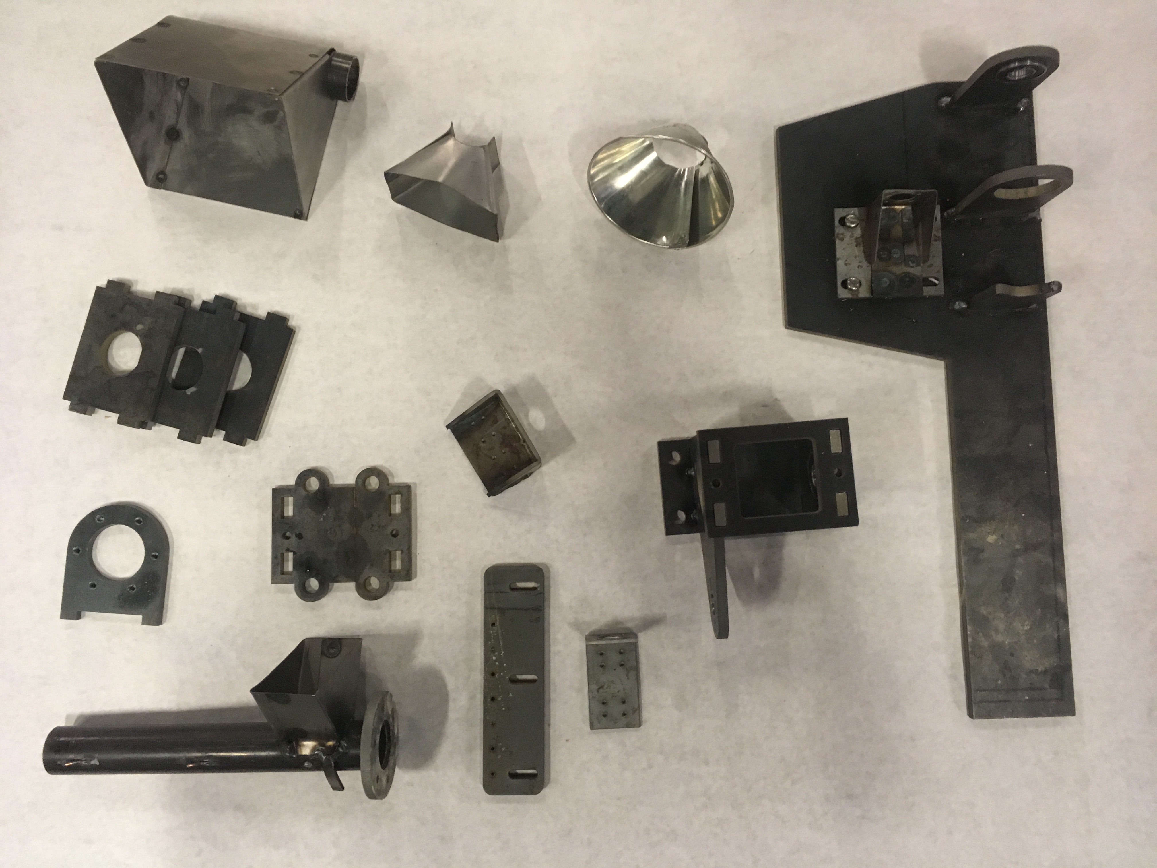
Pictures of Prototype #1
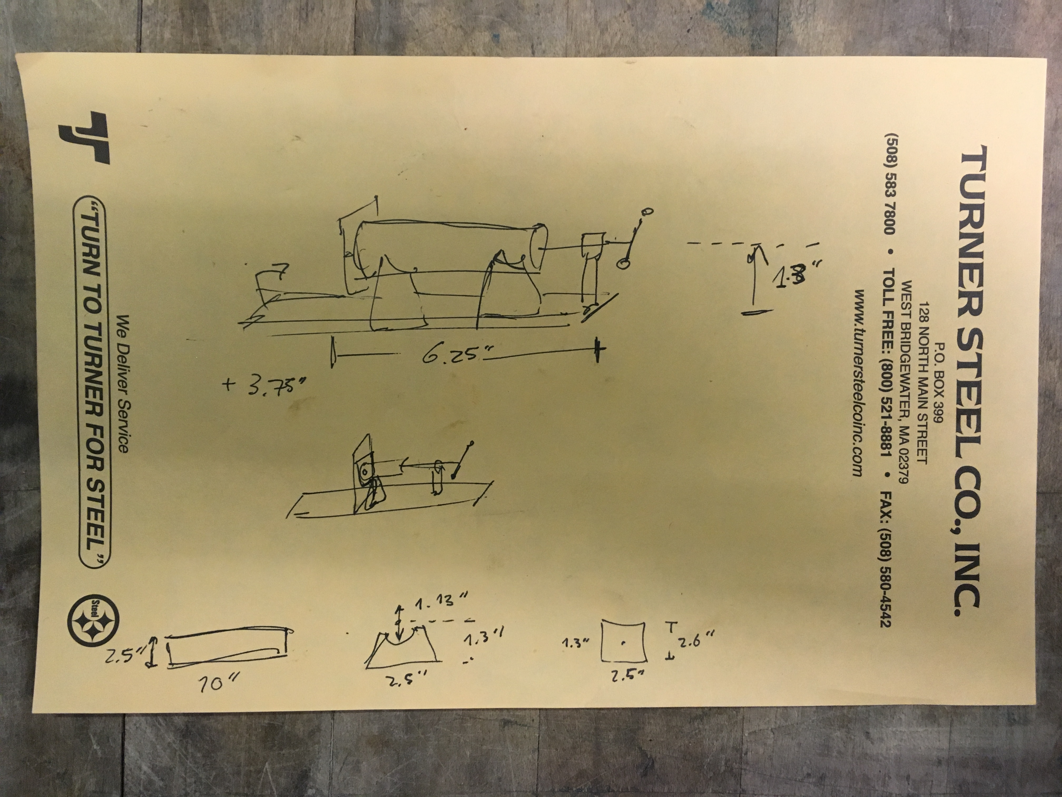
A rough stectch I used to hack together a protoype to see how the material melted and what temeratures I could get with the heating coil.
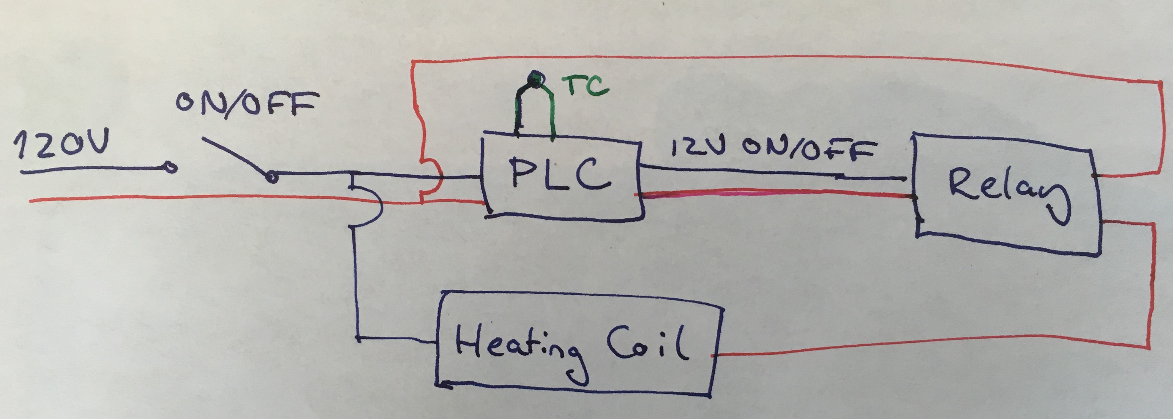
A simple electical circuit used in the protoype.
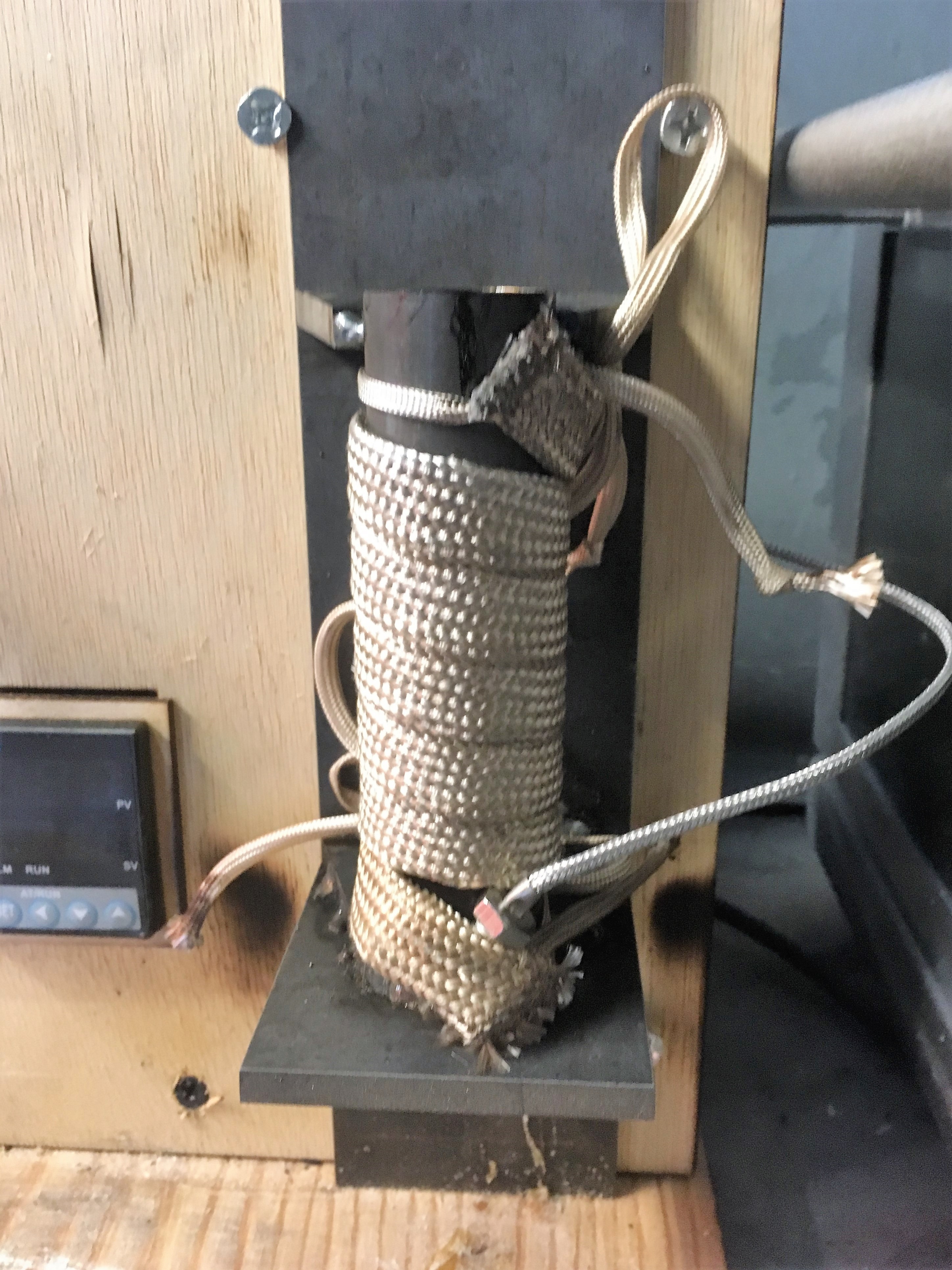
With my first test meting material, CoPal, the material froze in the nozzle. There is a huge conduction pathway into the base of the structure which I need to decrease, and add mosre heating to this region. I ended up heating the nozzle with a propane torch and got the melted CoPal to flow out via gravity, but there were a lot of bubbles in the material. A lot of the material stuck inside the extruder, so a plumger to force it out at a constant rate is necessary (not unexpected). On the bright side the whole container metled within a few minutes.
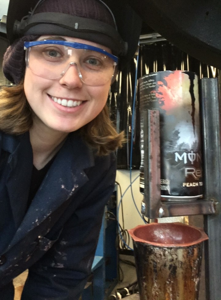
The copal has a bunch of floaties in it, so I bought strainers from an AeroPress to preprocess this material. Tested. The aero presss filter was too fine and the copal couldn't flow through, even with back pressure. I welded up a rig to hold a crucable of CoPal. Here my crucible is a MONSTER can because it fit so well with the filter. Realized thin aluminum melts pretty easily though and I got some holes in the back yard experiment...
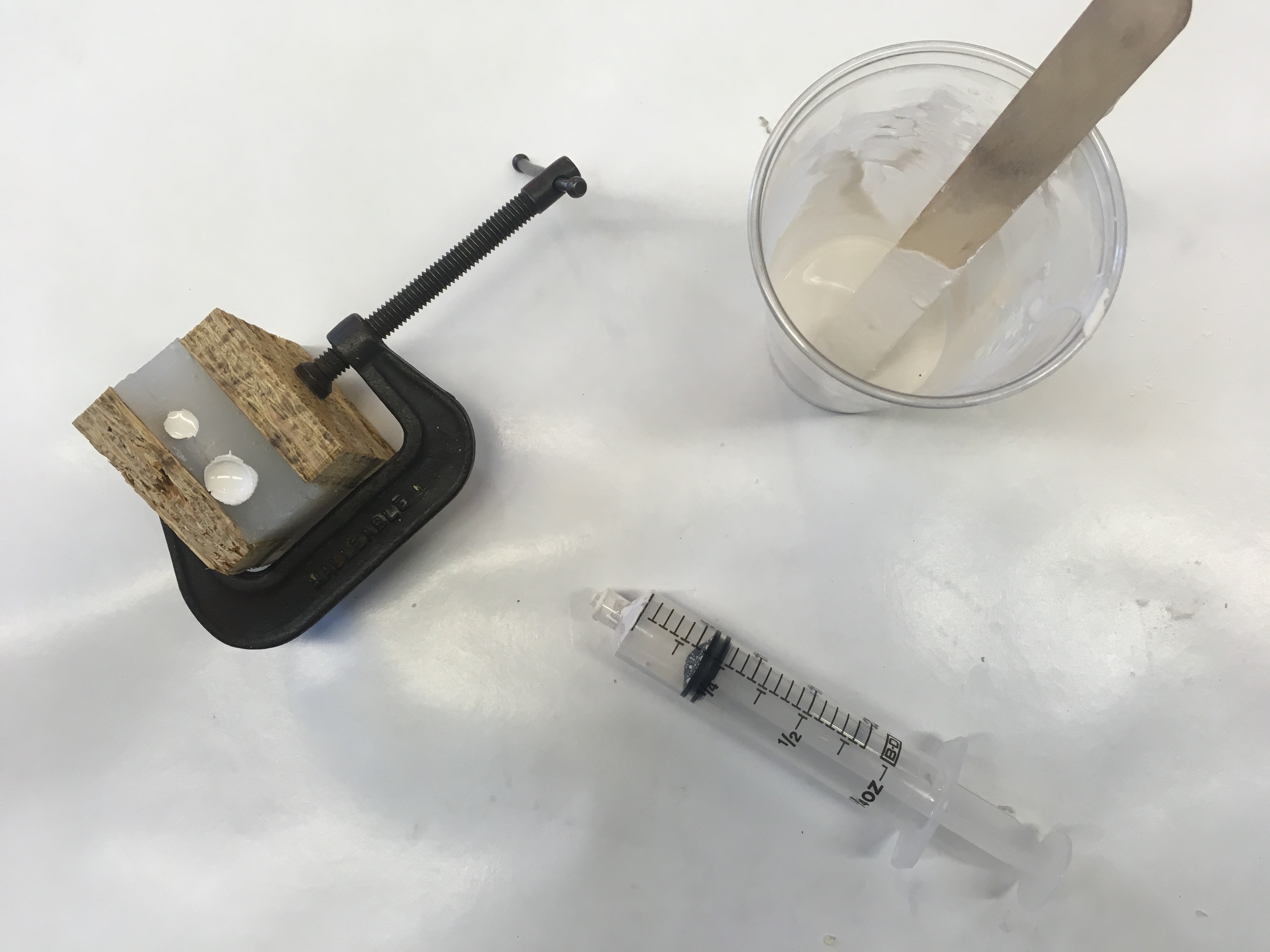
CAD for a mold to cast the turn screw.
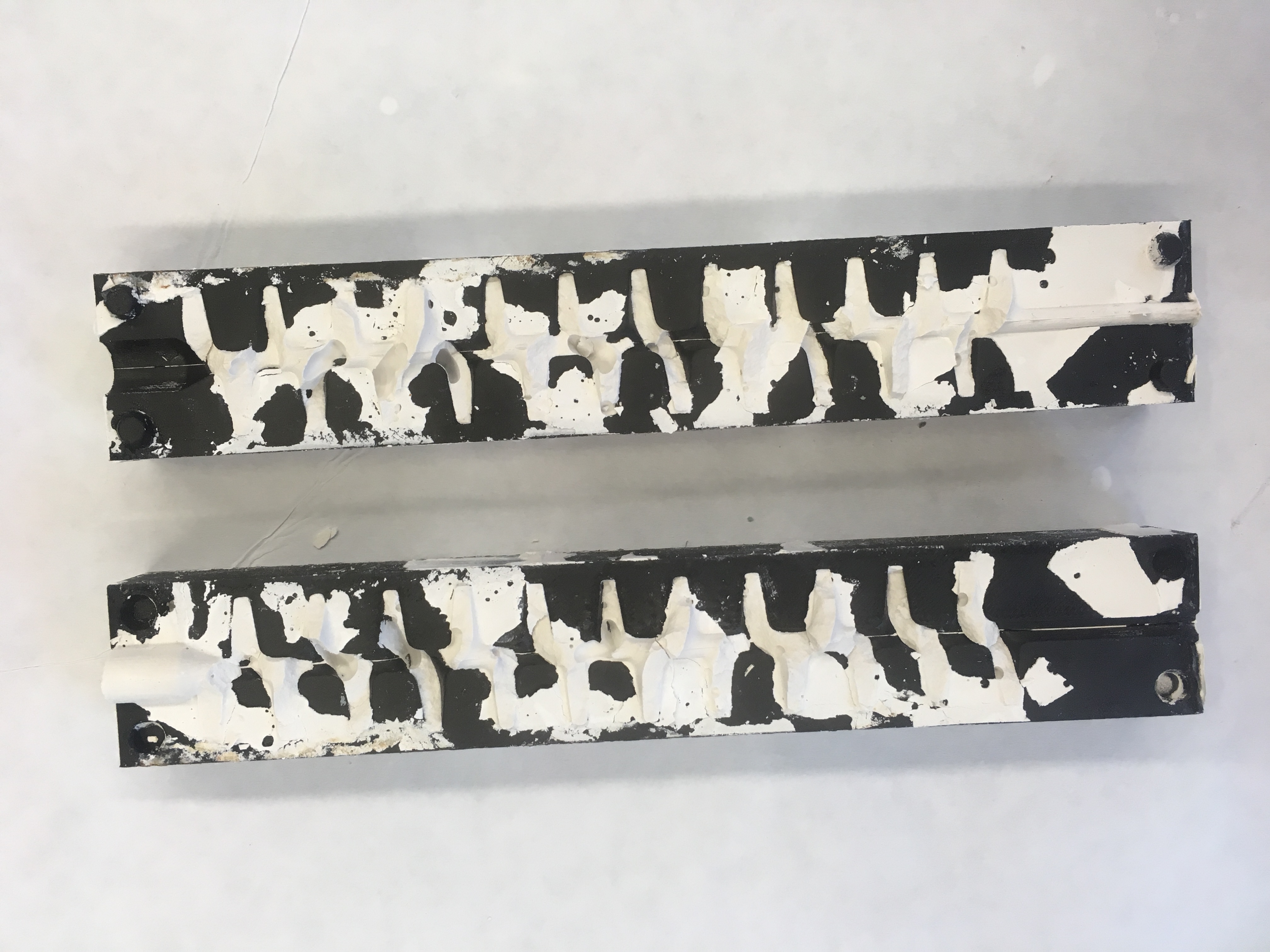
I 3D printed the mold with Onyx on a Markforged printer and coasted the mold with vaseline as mold release. Melted the vaseline off to make a smooth finish. I tried to cast the auger out of hydrostone. I pushed the liquid hydrostone in and tried to stamp out bubbles, but it didn't fill the negative fully. Need more consistent pressure.
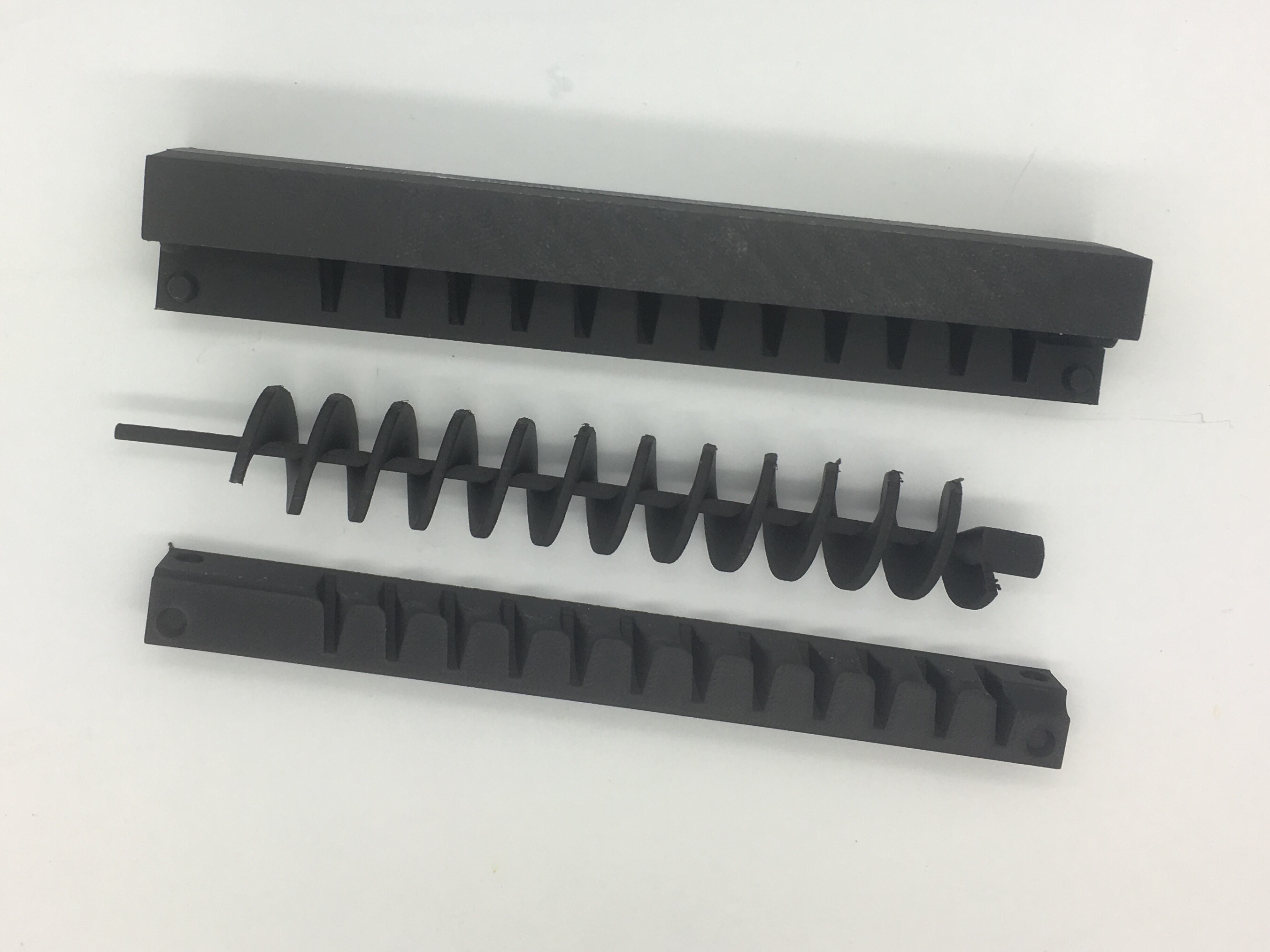
I also printed the auger to make sure the shape would come out of the mold, and practice taking it apart because I knew the hydrostone would be fragile.
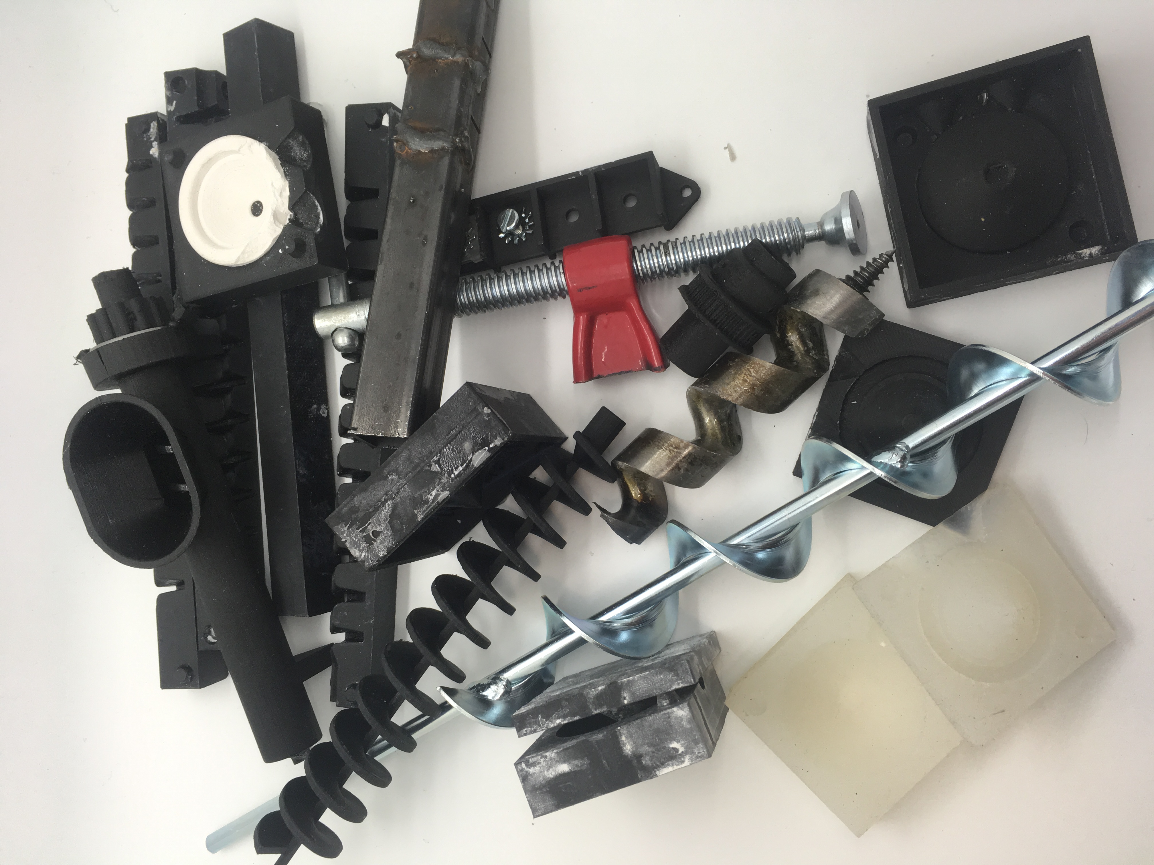
Before trying the casting process I was looking at using a drill bit as an auger, but was a little skeptical the pitch might be too steep and it wouldn't force the material out. In order to test auger pitches I'm 3D printing a injection case and will test drill bits, and various 3D printed augers with silicone. If the drill bit work, GREAT, if not, I can machine the auger.
In this test I experimented with a 0.5" standard drill bit, and wasn't able to force any material out. This was expected that I'd need a steeper pitch, but good to know. I tested with small solid particles as well as silicone lubricant which is pictured below. This is a dumb video because nothing happens, but documentation.
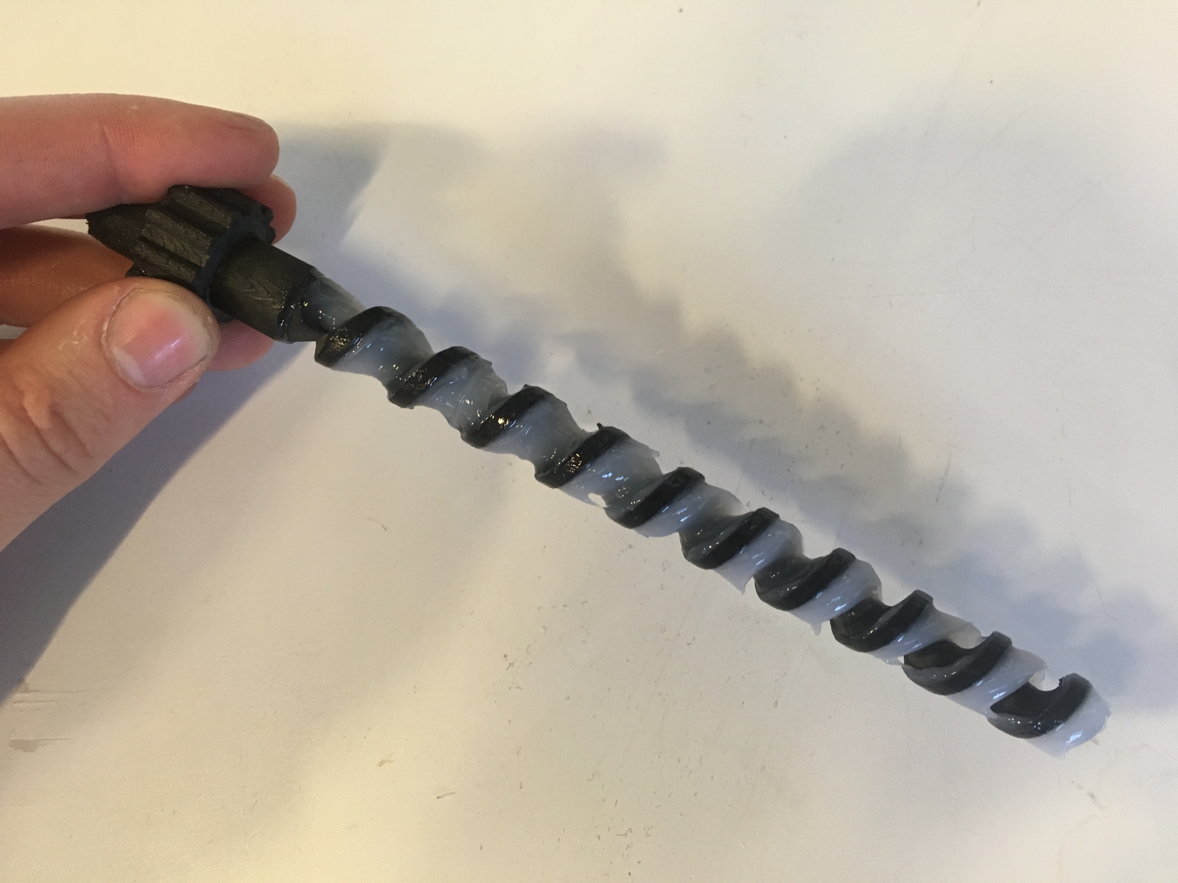
Testing with a 3D printed auger that has a 0.5" pitch. Twice as steeper as the drill bit. The silicone lubricant was able to travel through the shaft. I think this silicon lube is more viscous that the melted copal actually... I put a pulley into the 3D print, but since I didn't have the belt to measure it wasn't very good and I couldn't get enough torque transfer though the belt to drive this, so I just connected it to the hand drill again. Because the end was only a little over a quarter inch the chuck of the drill didn't close nicely and kept coming off. I couldn't get a video because I ended up just hand turning it, which is a shame because this experiment was much more interesting. Oh well, soon there will be video of a real molder though!
Tests for milling the auger... The Roland LIVES! Not sure it will work as well on aluminium though...
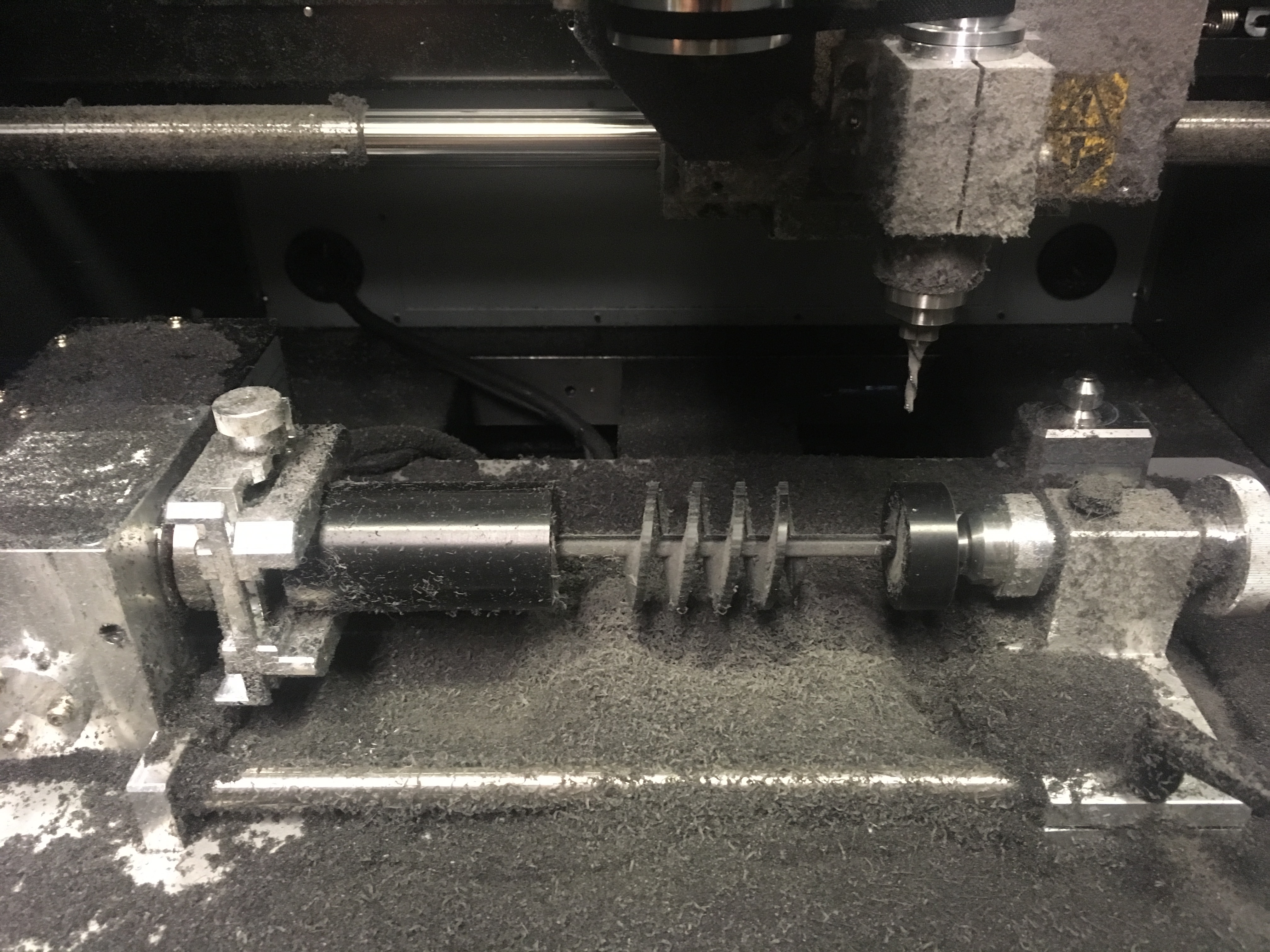
Here are two tests I did with the MXD-40A to see if I could machine the auger. The first shorter sample worked really well, wasn't a perfect surface finish but totally usable. The second 7.5" long sample is very similar to the actualy geometry I was hoping for for the auger. It actually caused a hard stop in the machine because it was too wobbly... so will need to adjust that, either making the center stock larger, or using a different machining approach. Since the part was held in compression I could see it buckling a little. I wonder if it's possible to hold a long thin part like this in tension instead...?
.jpg)
So after everything I ended up buying an auger off Amazon for $20. Super good deal, and I've now tested it and material travels well! Now building up the body to put all these peices together.
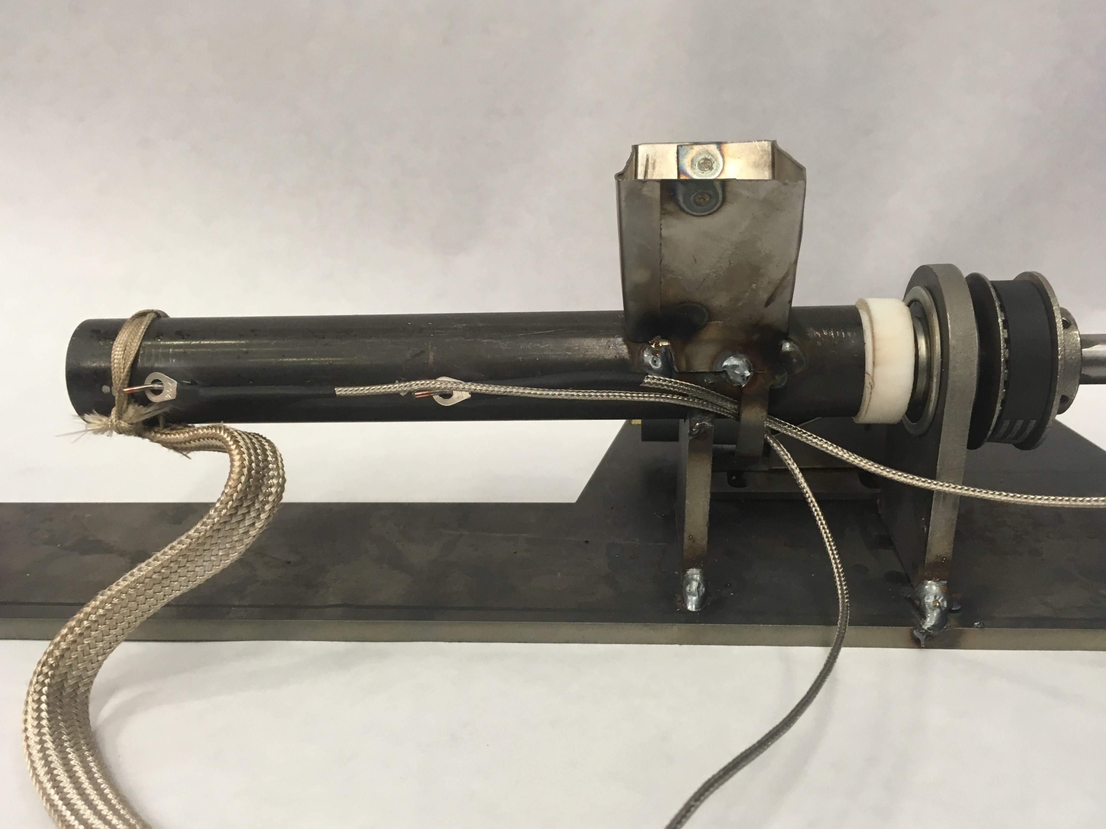
Testing prototype #2 with the PID controller and initial set up... This set up was not mechanically stable AT ALL, and as soon as the copal left the heated region it froze. The frozen plug stalled the aguer and had it torque against the body moving everything...
On the bright side it was easy to torch away the copal and clean the machine...
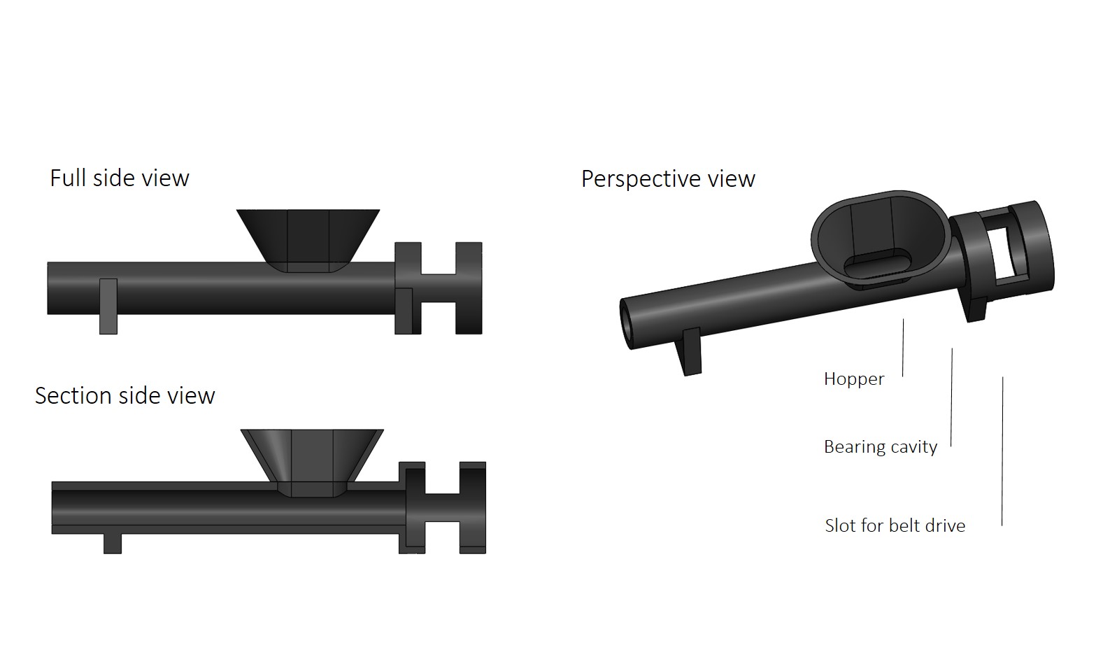
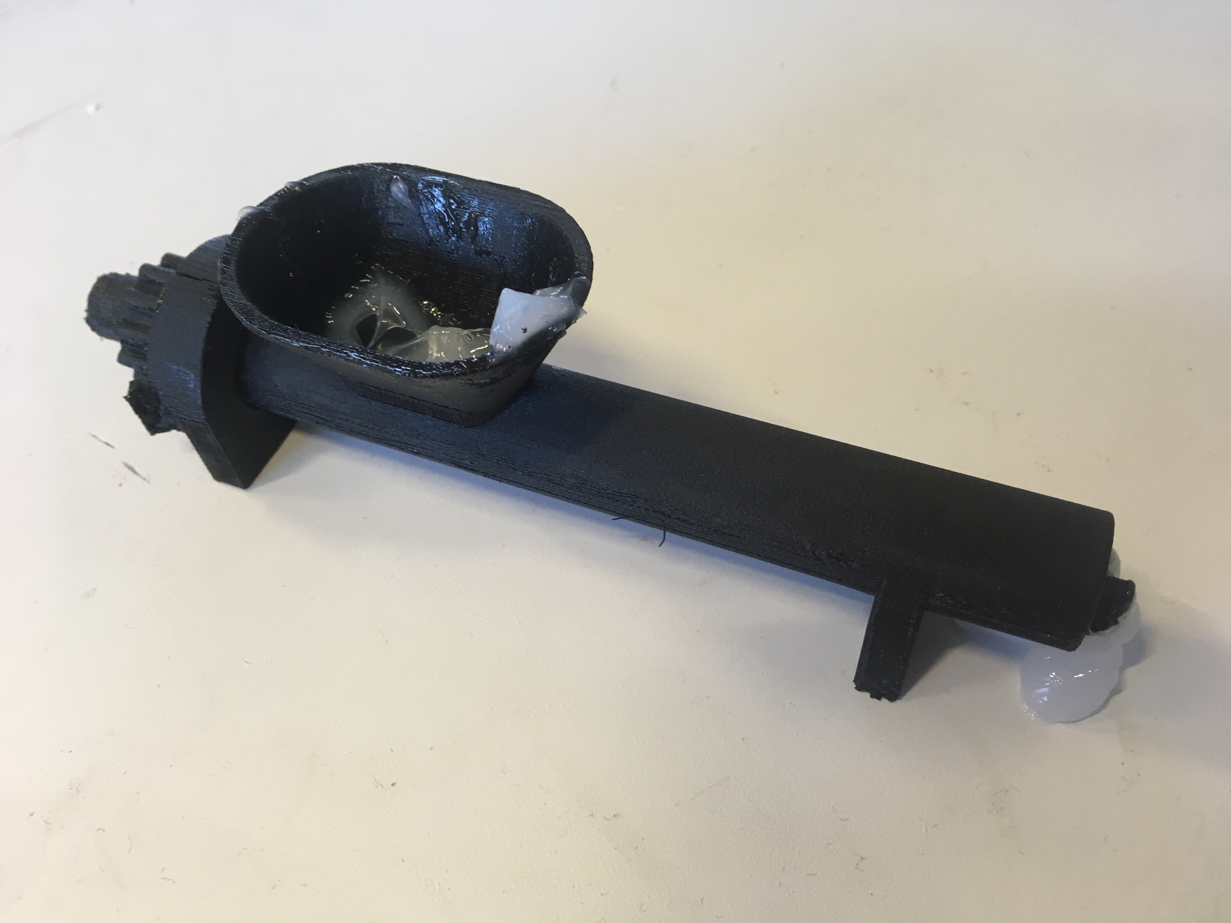
Re-designed for a little bit more mechanical stabily. I chose to mill out a slot to seat the hopper on instead of having two sections of tube to line up. Connected more things, and testing with prototype electronics. I got bearing and a pully to drive the machine. Since I'm using mostly what I've scronged I tested a few differnet pullies, and 3D printed this one for the first trial. I needed bigger teeth, so Jake ended up giving me a nive steal pulley later on... I also turned a little PTFE spacer to act both as a heat separation, sort of as a bushing and to keep particles from falling backwards. I cut the auger and ground notches for set screws and retaining rings.
This is the progression of trial pullies... minus a few other 3D printed variants.
I also tried milling the pully on the MDX-40A, but since SRP player only has the tool come down on the center line it couldn't make the gears, even though I think it physically could machine it.
I had some fun making little tabs to hook the thermocouples onto, as well as something to keep the heating coils from rotating...
Here's a video with the auger rotating...
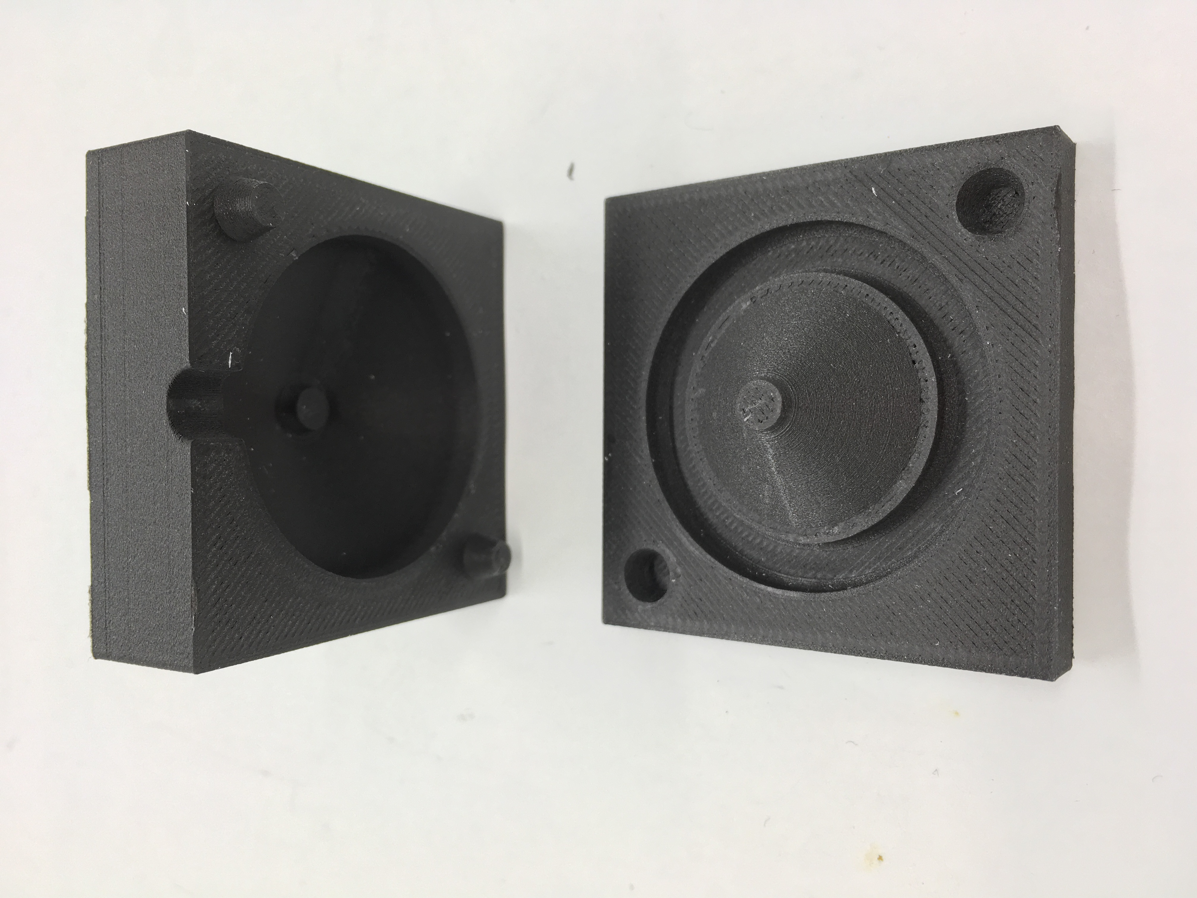
I wanted to make the nozzle out of ceramic so it wouldn't be as large a heat sink as the steal version in protoype #1. I 3D printed some molds, and cast a protoype with hydrostone.
And pulling the molds apart the hystrodtone broke... Realize I forgot mold release. I also got cocky and didn't weigh out the water and powder, just went by eye... no bueno.
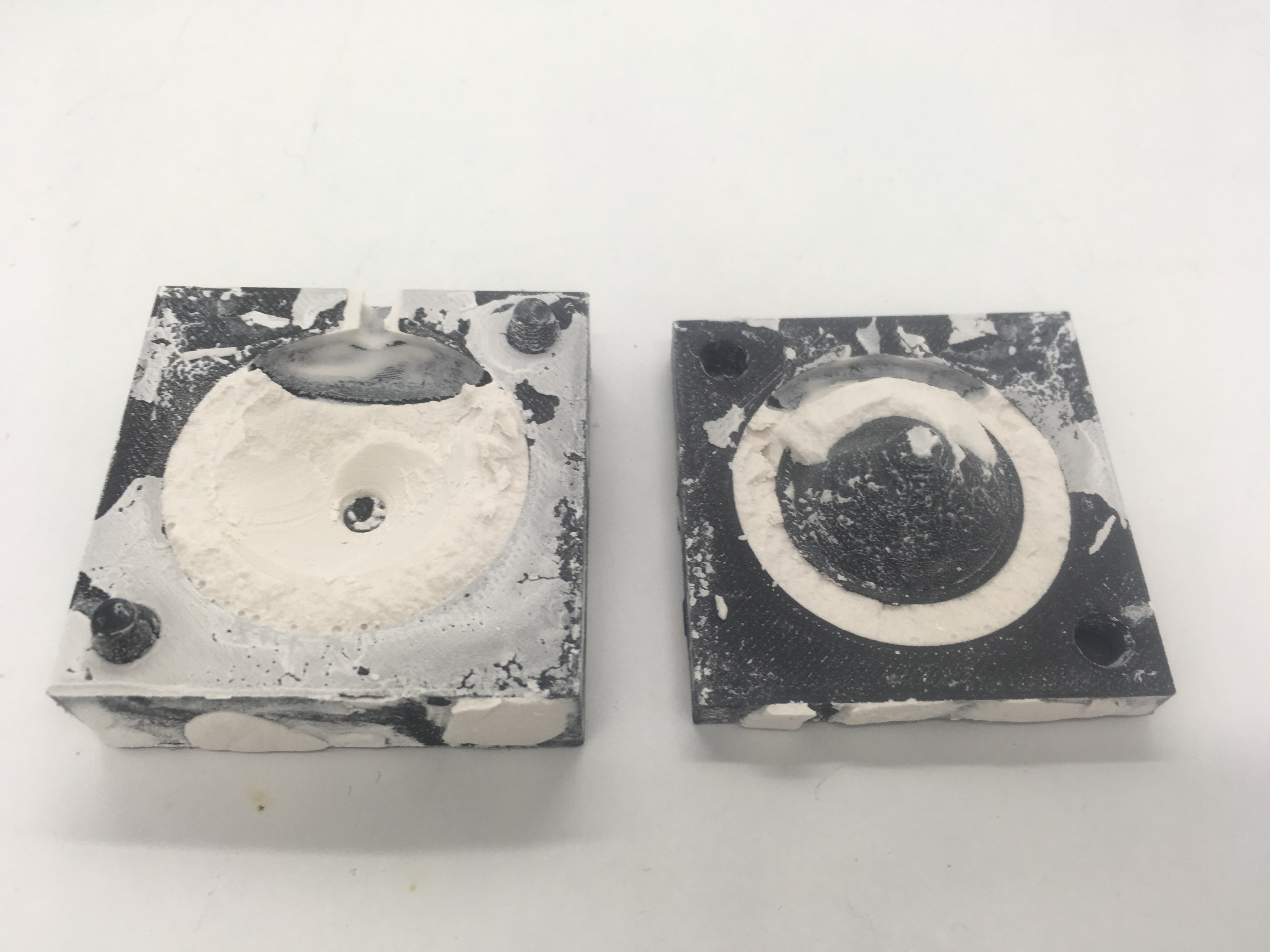
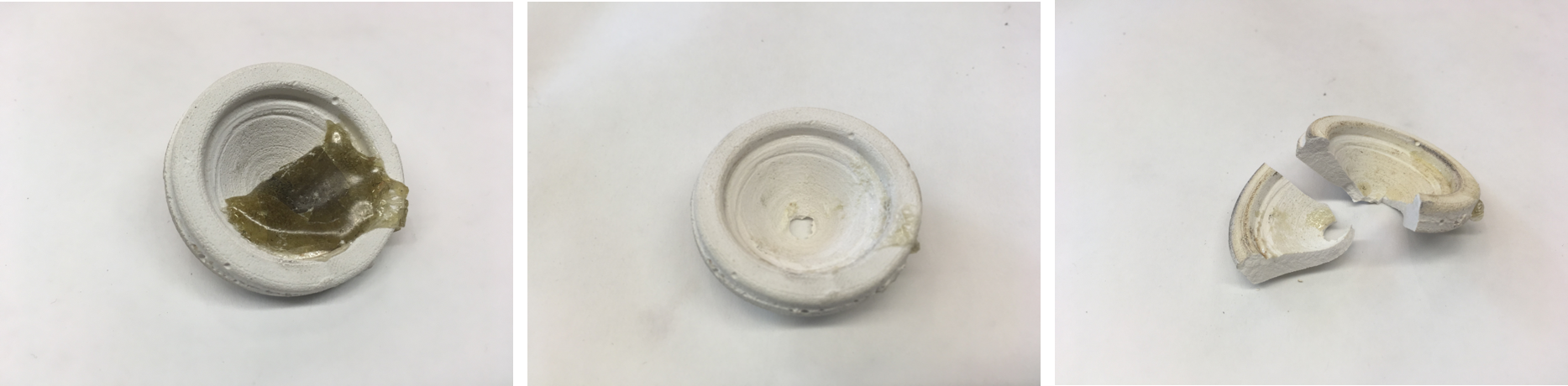
Remade the nozzle mold with a few improvements. I added 2 hole, one for the material to go in, and one for excess to come out so I knew it was fully filled. I measured the volume of the cavity in solidworks, 0.46 cubic in, or about 7.5 mL, and I filled a syringe with the liquid hydrostone. Then I pressed the syringe into one of the cavities and could see the volume filled up before overflowing. Then into the vacuum chamber to remove air bubbles. I also remembered to put some petroleum jelly on the mold as a mold release. The part still got stuck though... even though it looks MUCH better. The chips are from me trying to pry the part out of the mold with a screw driver. I'm thinking about making the nozzle a different way... Potentially casting the mold out of silicon. Looking into machining ceramics instead of casting.
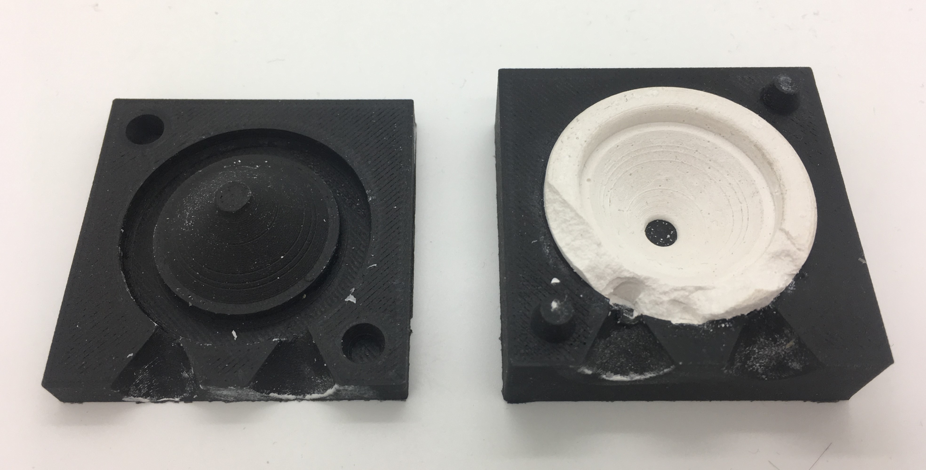
Re-made 3D printed molds to cast silicone molds to cast the nozzle again. This time it came out great! It's very fragile though... I've already broken one.
Unfortunately, the copal froze and stuck to the hystrostone. The copal cracks off steal pretty easily, and I could scratch a lot of the copal off the hdrostone too, but the hydrostone scratches pretty easily. I tried torching it to get the rest of the copal off and it broke. Thermal shock...
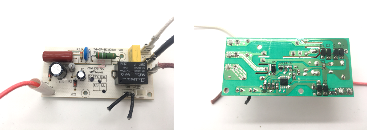
I took apart a coffee maker I found, because I think it's interesting to see how production products are made. Specifically in regards to the electincs. I'm curious what the basic electronics needed to heat something up are, and how they implement safeties within the produce. My worst nightmare as an engineer is designing a product that could harm someone, and I've woken up many nights with dreams that I've accidentally caused a fire. When I look at this coffee maker, it's pretty simple though. This board was nice because it's well labled. It looks like just a timer and a relay, and of course there's a thermal fure in line with the heating wires. I'm also planning to poach that SMT relay for the auger motor if I get to making a board...
Spent a bit of time trying to autmatically log the results of my experiments. I was using a RasperryPi both to control programable temperature profiles as well as connect to the internet and log the results.
Google App Engine has some depricated sections and I'm having issues getting the data to Authenticate... Looking into Adafruit's new IO platform... Adafruit IO. directly sending to a server?
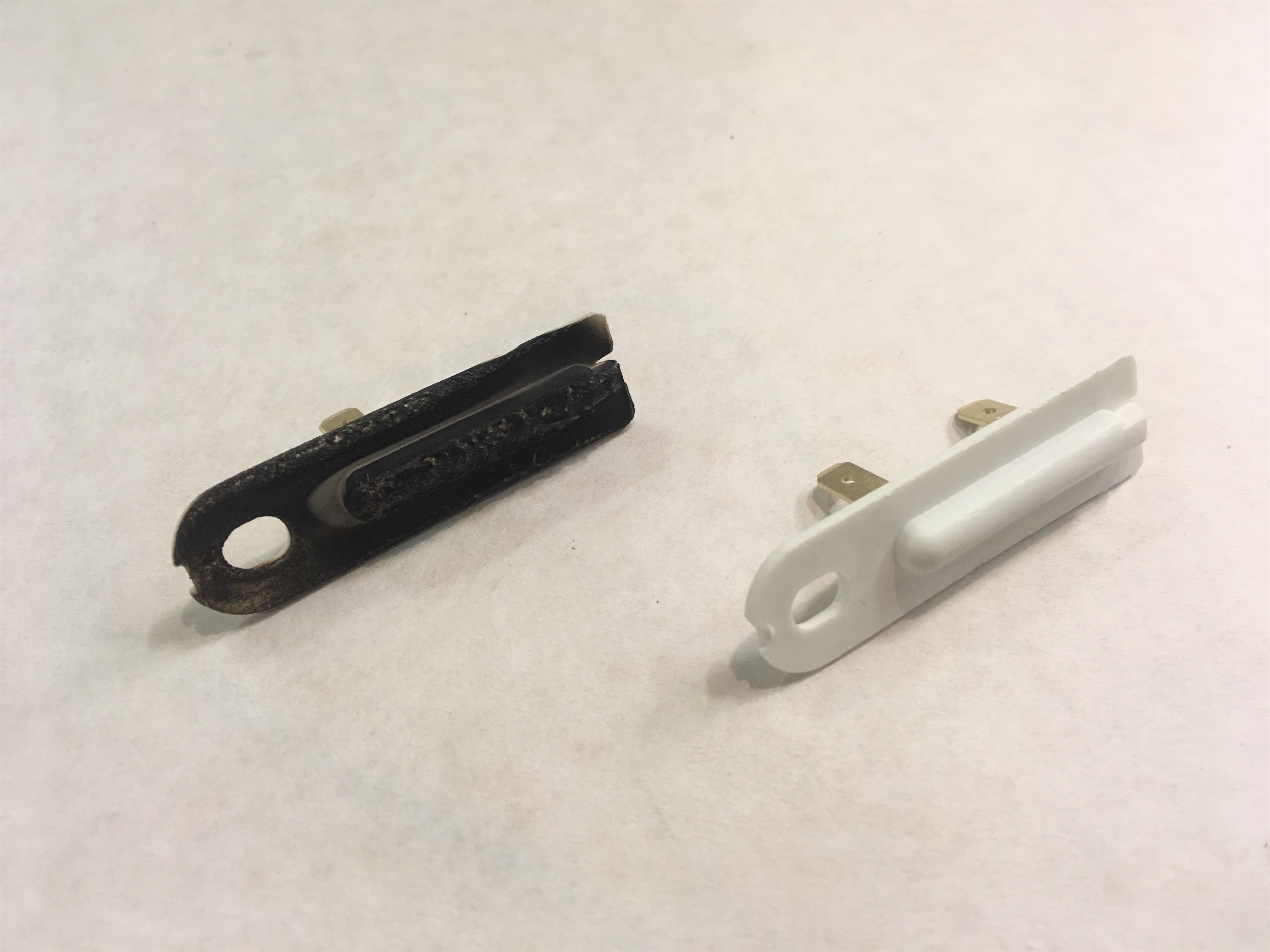
I'm getting the machine up and running with prototype electronics, and and starting to write the code to transition it to Jake's BreadBoardBoard so my machine can be a "networked machine" but I also want to encorperate a few safety features into whatever electronics are being used as this will get to high temperatures. I bought these themal fuses as well as a mechanical timer. I took apart the mechanical timer immediately upon arrival and it was full of little gears and springs which got mis-alligned... so isn't working anymore. I tested one of the thermal fuses taping a thermocouple to it and torching it and can confirm it looses continety when on fire. Stuck the fuse on the heating coil.
Thermocouples notoriously hard to work with because their signal is on the order of millivolts. If there's any noise on the wire the signal won't be readable, and they need to have a reference temperature for cold junction compensation as well. To skip some of these complications I used a MAX31850 thermocouple to digital converter. Prototyping with the Arduino is annoying because the MAX31850 has a 3.3V data line, and the Arduino is 5V, so I need a level shift. Trying to implement these chips with the BBB reading lots from online. For documentation of the BBB implementation click here.
Really?? Are we at #4 already...
Since V3 was a bit wobbly the tip of the nozzle moved around and didn't seat very nicely in a mold. Part of this was caused by the lock ring I had between the front bearing and the PTFE spacer which was bent, so pushed unevenly on the tube. I'm also remaking the bearing mounts so they sit better, and are keyed into the base before welding. I'm also re-making the motor mount so it's stiffer. Additionally, with the remaining 36hrs in this class I'm trying to add the injection part of the injection molder. I found a massive 12V linear actuator to use, and ground a D in the pulley so it can slide along as the screw is push forward, but still drive the rotation of the screw. There's a ton of backlash, but that should be perfectly fine for this system as precision isn't required with in the rotation of the auger.
I'm designing these modules to fit onto a double wide 80-20. The injector, the puck shooter and the molding segment. Even though I rebuilt the bearing mounts theres still a little wobble. Where is it coming from? Sorry the video is also pretty wobbly...
Material test time. In this experiment I was particularly interested in seeing how much pressure the CoPal supported and if it's enough to force the auger backwards as it pushed material.
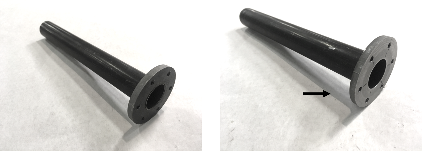
I took out the tube and turned the front flat. It was really surprising to me how out of allignment it was! In the picture below you can't tell too much, because in the after shot the whole face is faced, but as I was turning it I could see when one hlaf was faced and the other half untouched very clearly.
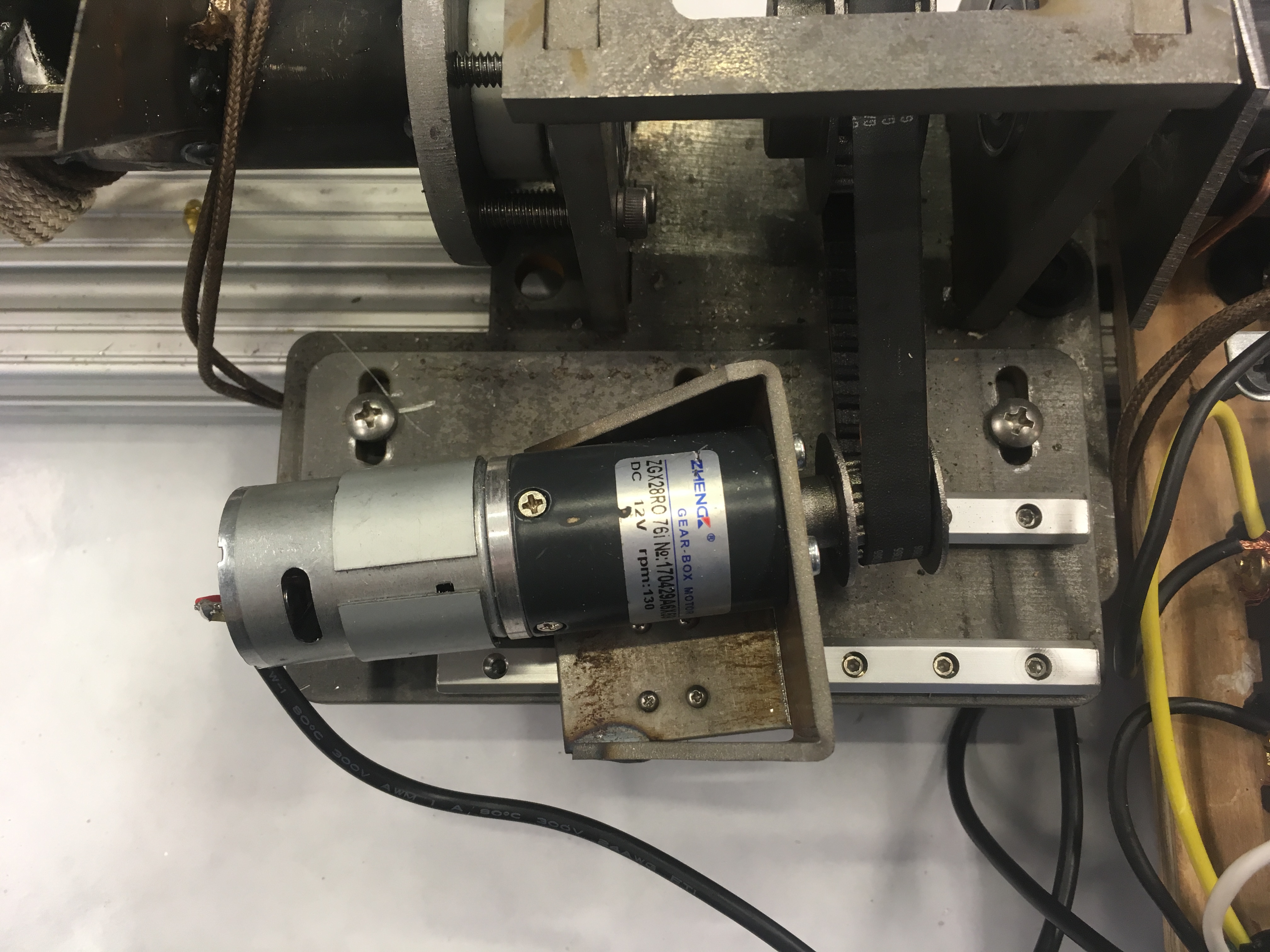
Adding a screw ram. I'm using a massive linear actuator that looks like it might have come off a door. Above there was a video of the pully sliding along the auger shaft. Since the grinding was NC, it's a little rough and that got stuck. Now I'm puting the motor on slides so it can slide back and forth as the auger moves.
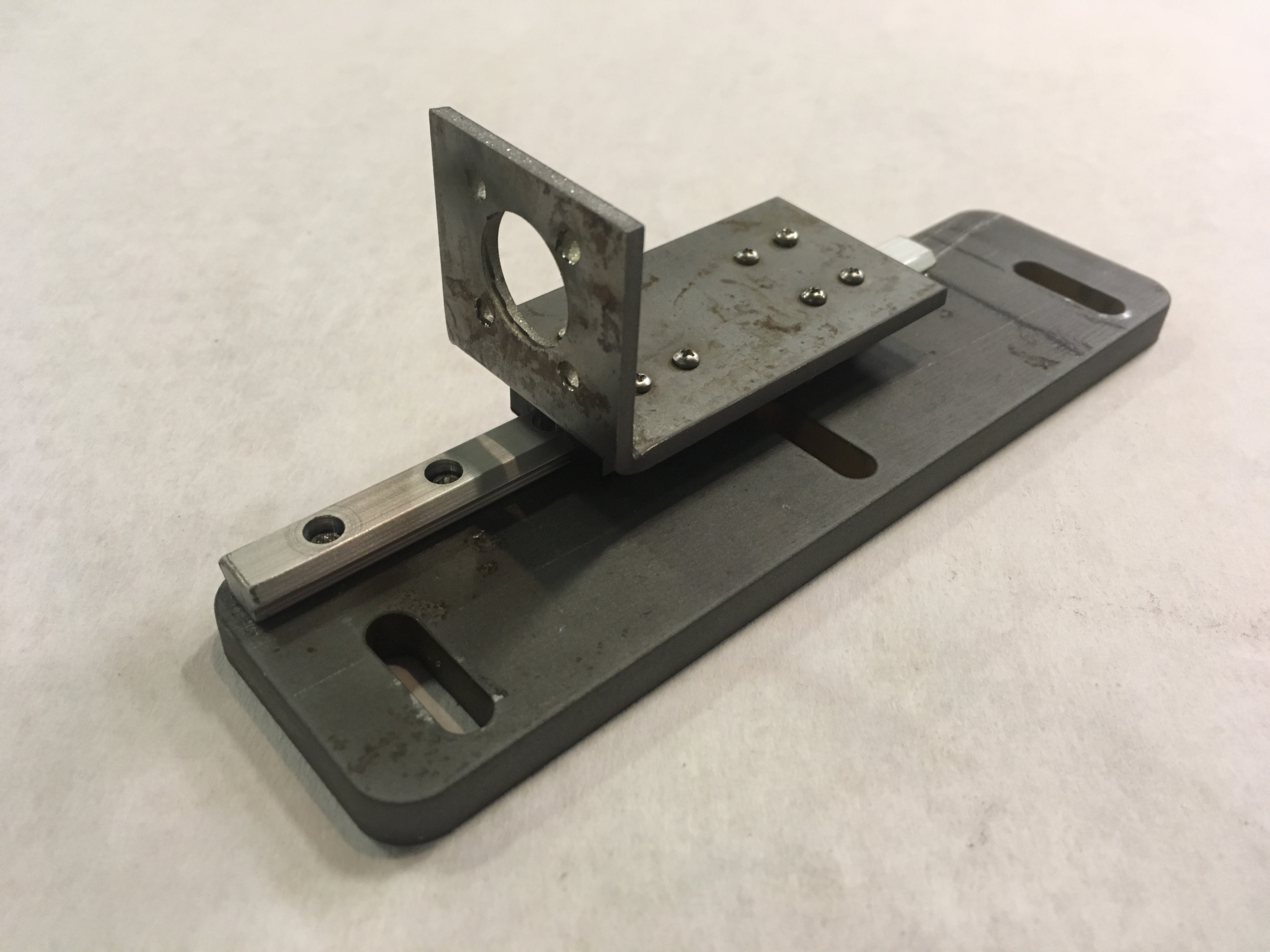
There was too much play in the above slide, because the rail and cariage and screws and clearance added up. I re-design and rebuilt the sliding motor mount so the carriages would be side by side instead of front and back to reduce the amount the motor could rotate. It still is a little off, but it held the belt.
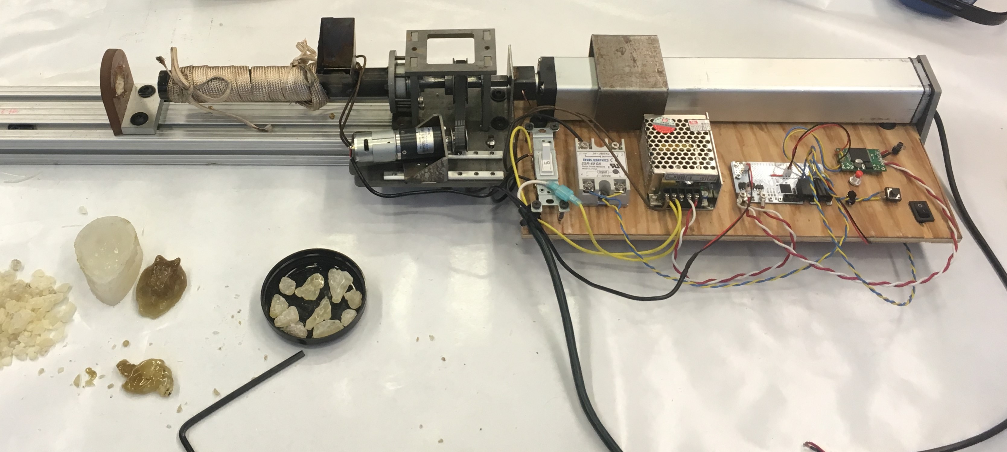
This is the full system put together for the demo. Still needs some love, but all the parts are there.
To drive the linear actuator forward and back, I'm using adding an H-bridge. Still some work to get this connected to the BBB with timing, but heres a demo of the mechanical system working.
Okay... yeah... the motor mount could slide a little bit better...