Final project

Background
This final project serves as the capstone for this class-- combining various skills that we've picked up over the past few months.
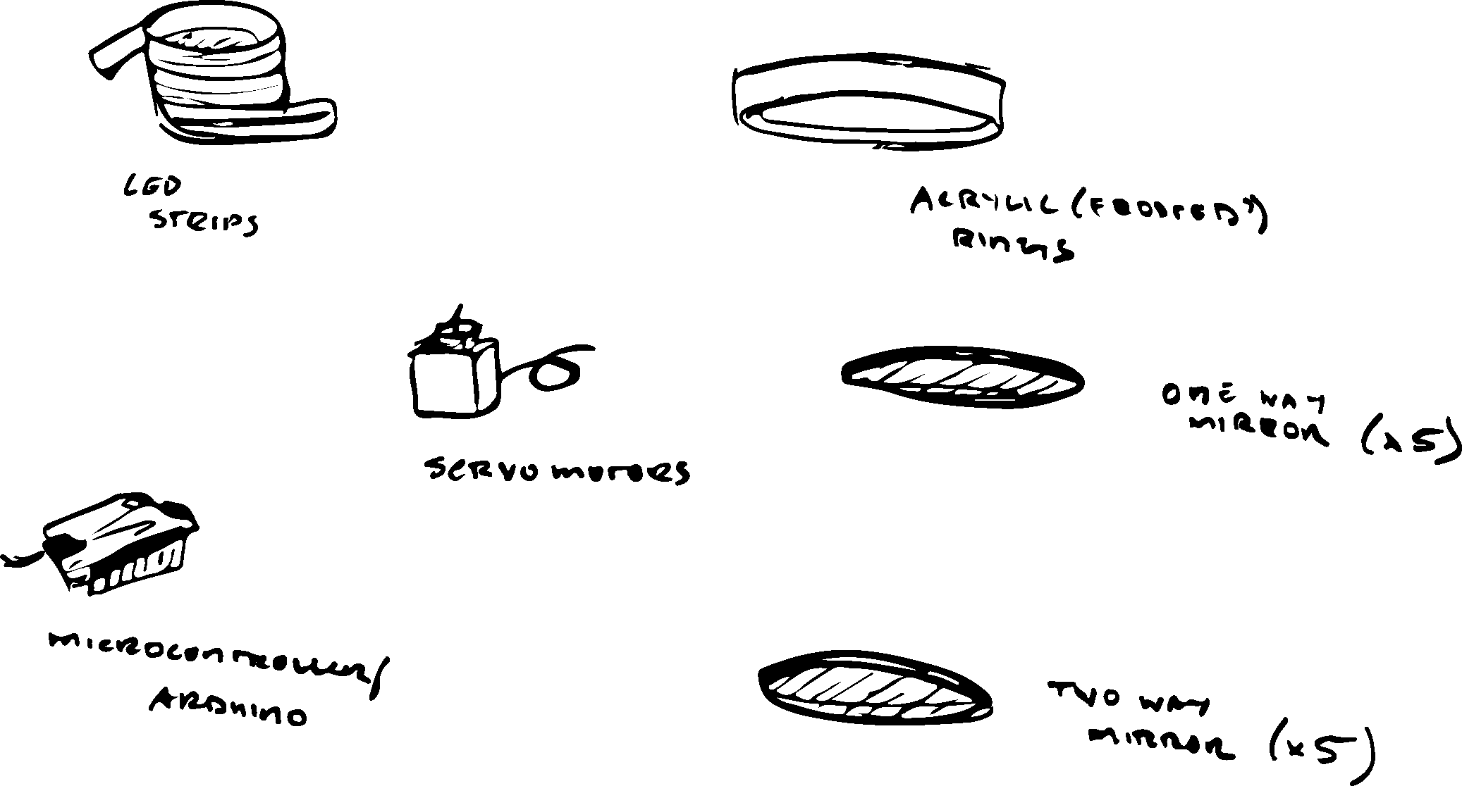
Materials
These are just some sample materials I think I'd need to construct the model in real life. None of these are set in stone, just a general idea.
Idea
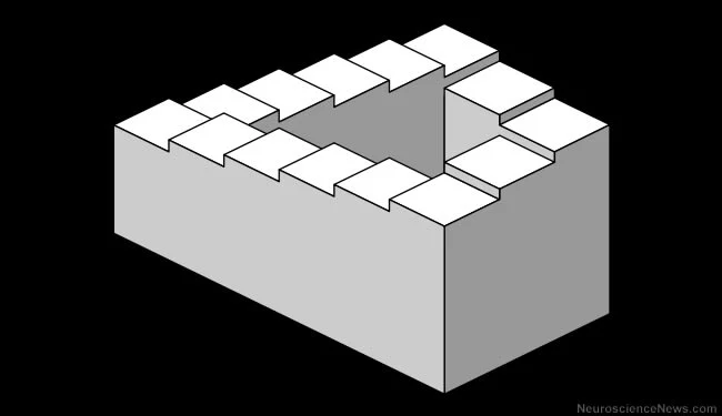
Optical illusions are super rad. They challenge our sense of reality, provoking feelings of curiosity and wonder... plus, who doesn't like looking at cool shit?
For this project, I wanted to find a way to combine my love for optical illusions and lights with my desire to try out a variety of different fabrication methods. I landed on an idea I feel excited about, although the actual form and interaction design may warp over the semester as I learn about new materials and sensors.
There are so many optical illusions out there, some more mesmerizing than others.


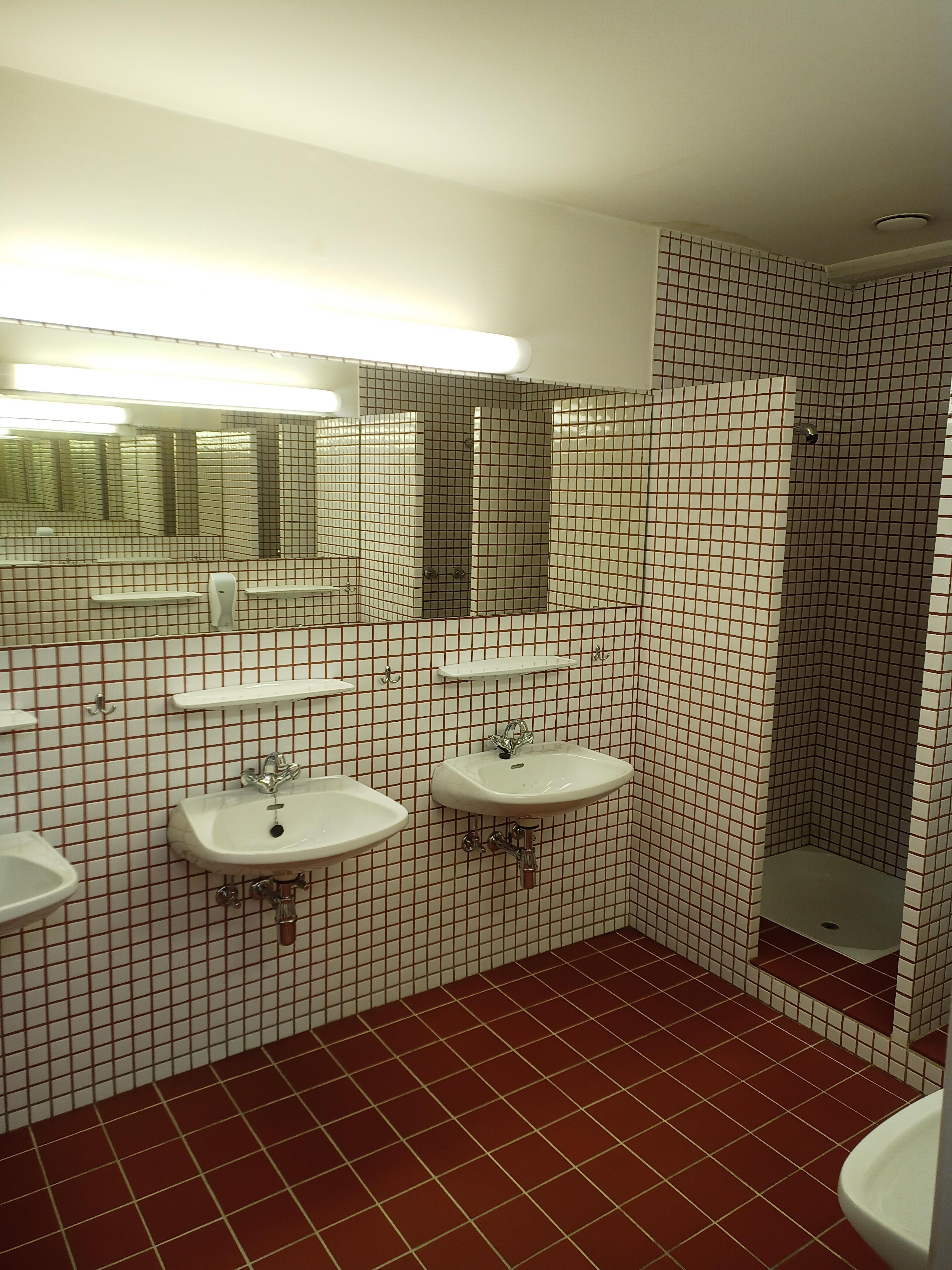
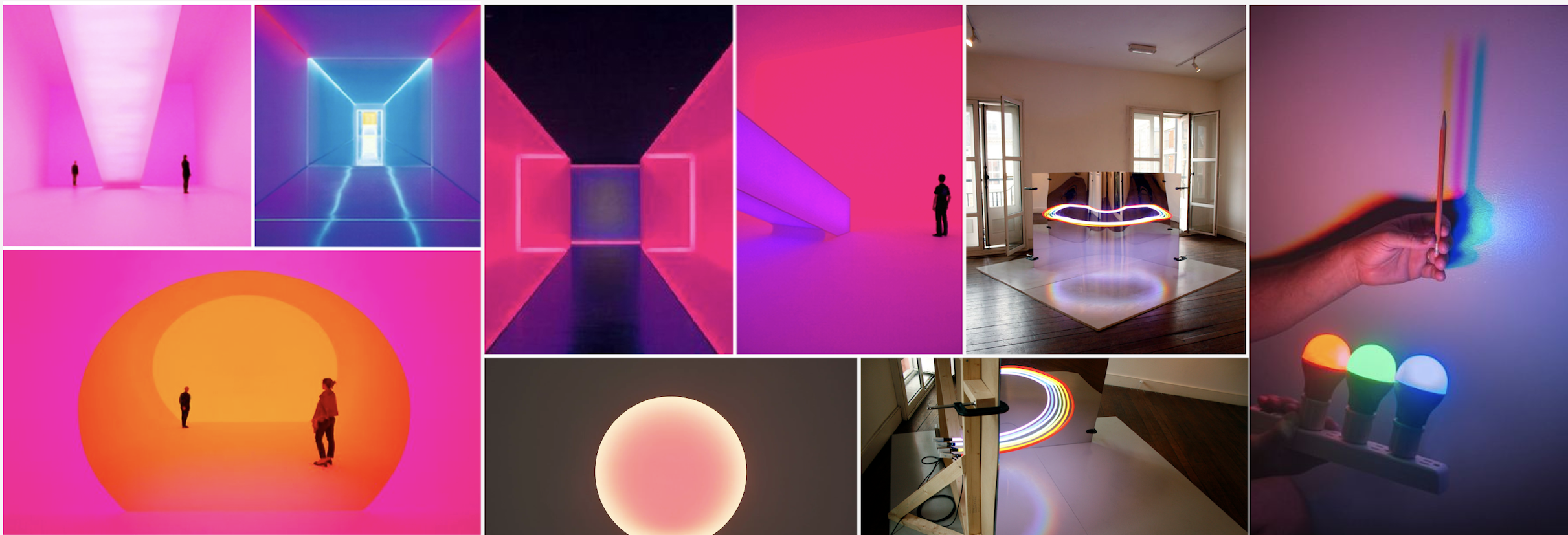
After doing some research to see what illusions I could replicate in real life, I ended up landing on a complex infinity mirror design. Infinity mirrors are made by placing two (or more) parallel mirrors on top of each other with space in between, which is a phenomenon you've likely experienced in fitting rooms, hair salons, and bathrooms with more than one mirror. This creates a series of smaller and smaller reflections that appear to recede into infinity-- a disorienting and sometimes uncomfortable experience (as seen below).
To make this illusion more warm, welcoming, and mesmerizing for the viewer, I took inspiration from James Turrell, an American artist who has dedicated much of his career towards creating immersive installations using both natural and artificial light to warp the viewer's perspective on reality. I used examples of his work and other artists like him to create a moodboard best described by words like "immersive", "sensorial", "disorienting", and "trance-like".
3D modeling
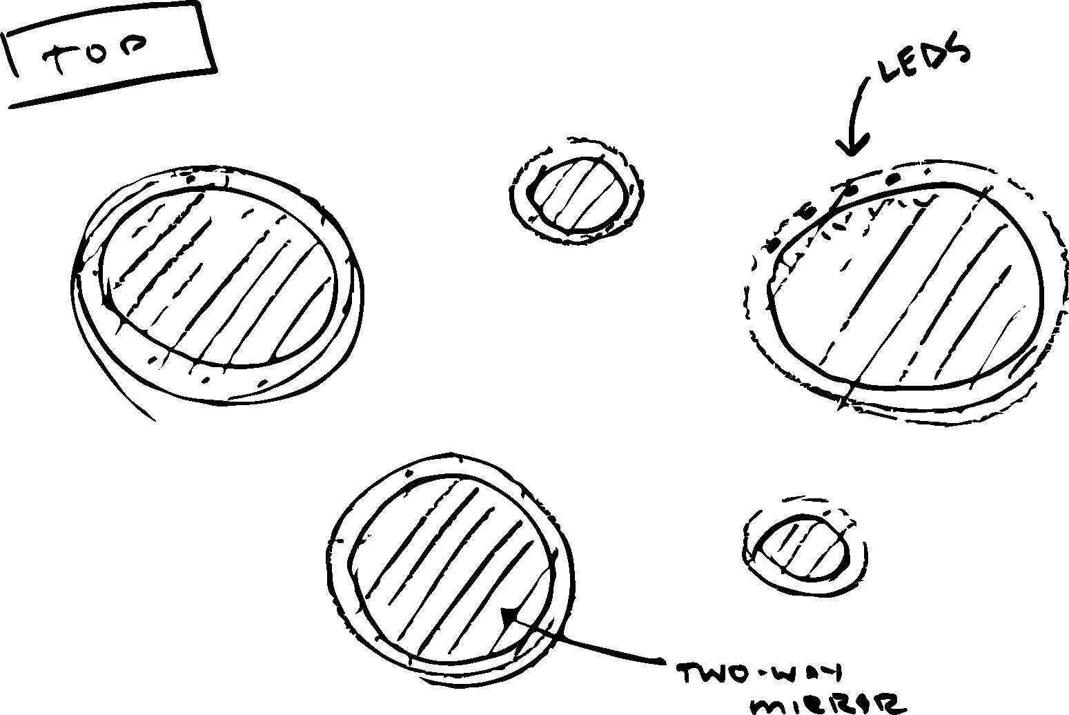
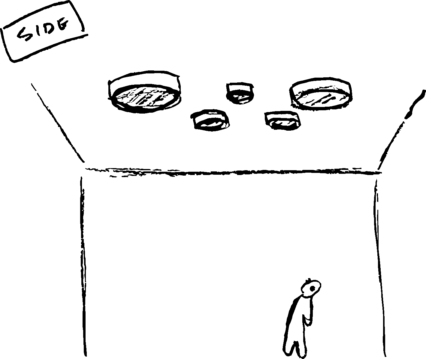
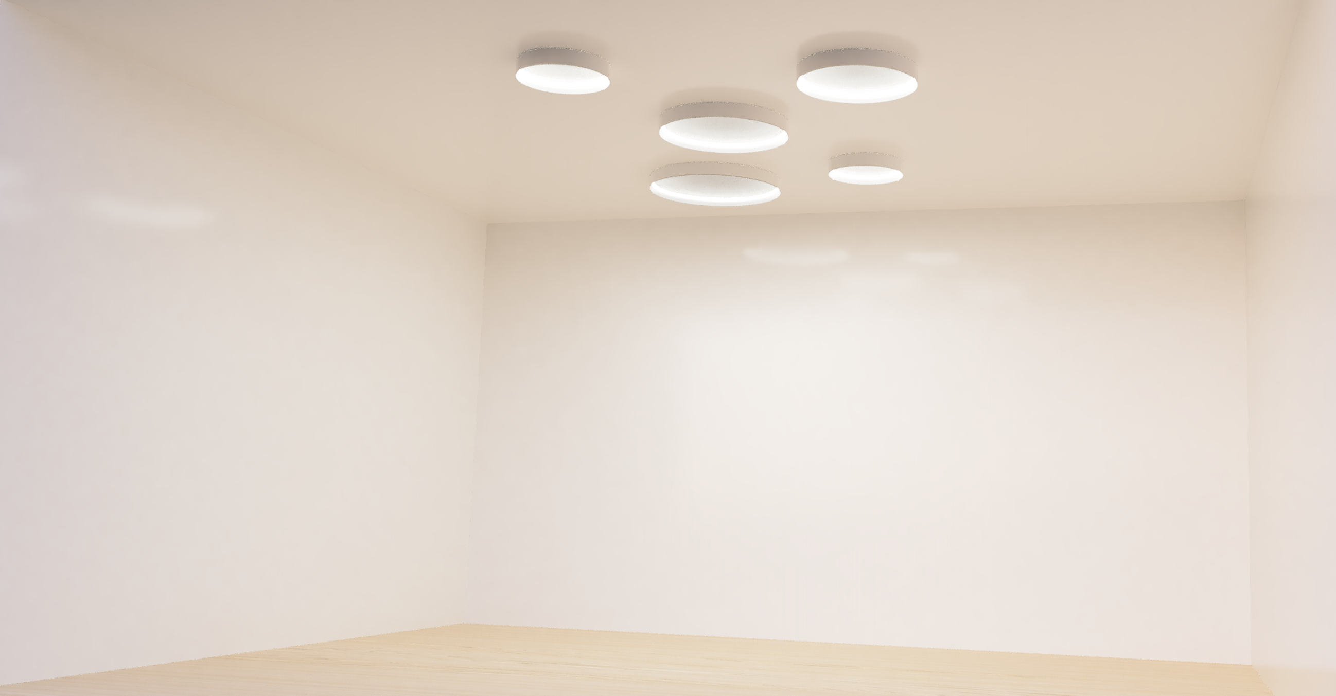
Before I touched any CAD programs, I iterated through a series of sketches until I landed on the following design: 5 infinity mirrors, spaced out randomly on a ceiling, with servo motors attached to change the angle of the mirrors as a person moves below them.
Then, I started the process of 3D modeling my design in Fusion360, where I later did my best to render it.
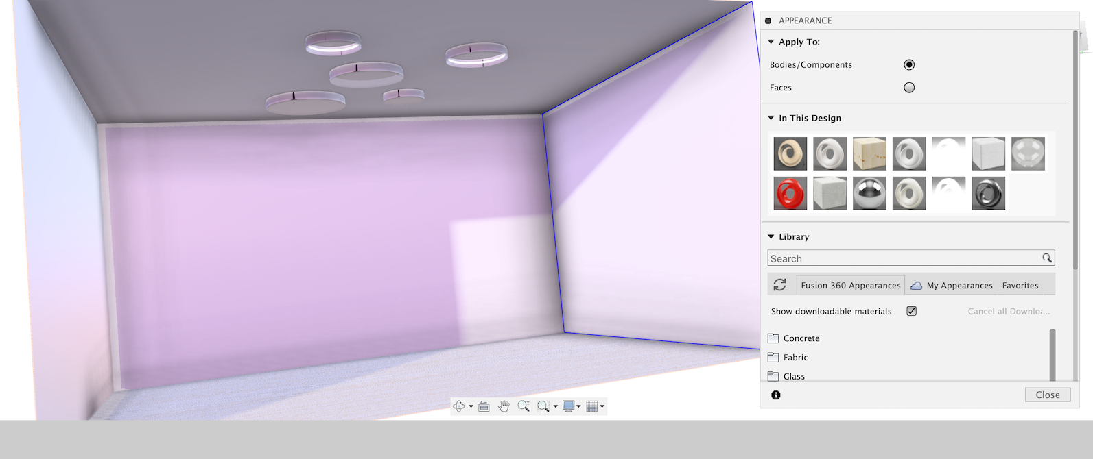
As I learned more over the semester, I decided to scope down my project into something more bite-sized, which in this case was a singular mirror that would be able to track a person’s face and actuate accordingly on two axes.
I spent a TON of time designing the architecture, circuit, and code to try to make this project work, only to realize about a week from the final presentation that I would NOT have a sufficient amount of time to get something working. If you want to see some of the work I did that just didn’t pan out, feel free to check out my Input Devices week and Output Devices week where I spent a lot of time figuring out how to translate facial detection coordinates to instructions a stepper motor could understand. I even ended up making the mirror and frame, which I’m actually very proud of! I learned a lot of woodworking skills here, both manual and automated (with a fancy Shaper router).

Changing my vision
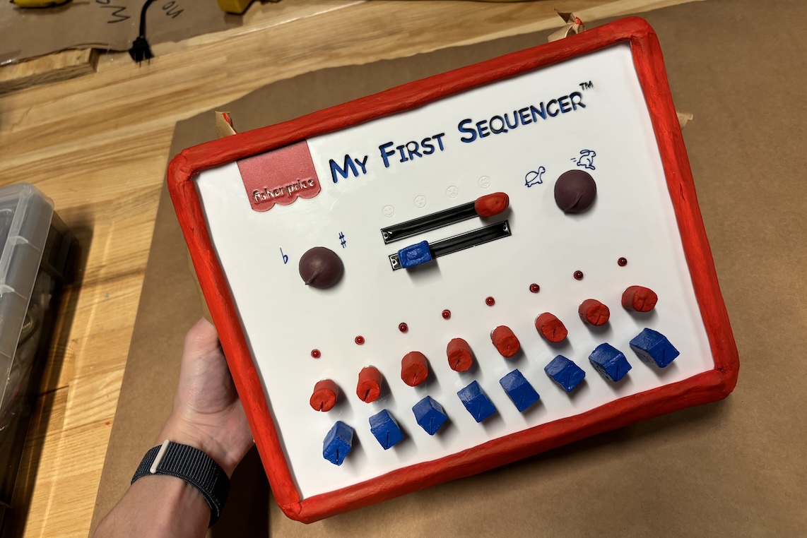
I decided to pivot to something more achievable with the time and energy I had as the semester came to a close. I landed on the idea of a sequencer that is so dumb simple to use, that a 5-year-old could use it. This sequencer has knobs to control the eight steps of a melody, eight steps of a bassline, and other controls to vary the tempo, key, and wave shape.
Inspiration
Creating a sequencer that’s simple enough for a 5-year-old to use serves several purposes. By simplifying an instrument’s interface, you make it accessible for beginners or those who are new to music production. This encourages people of all ages, including children, to explore and experiment with music creation without feeling overwhelmed by complex controls. Additionally, a simple sequencer can be an excellent educational tool for introducing the basics of music theory and composition, helping users understand fundamental concepts of rhythm, melody, and harmony in a hands-on and interactive way. The simplicity of the interface promotes a sense of playfulness and creativity, allowing users to easily experiment with different melodies and basslines by turning knobs and pressing buttons, fostering a fun and exploratory approach to an entire art form.
So many people have great ideas they can never bring to fruition, simply because they don’t know how to strum a guitar or use a digital audio workstation. Simply put, the goal of My First Sequencer™️ is to break down barriers to entry in music production for anyone and everyone.
Approach
In approaching the development of a kid-friendly version of an 8-step sequencer, my research was a multi-faceted exploration that encompassed a range of influences and considerations. Firstly, I delved into the realm of high-tech sequencers, examining the features and functionalities of advanced electronic music production tools. This investigation aimed to distill the essential elements of sequencers used by professional musicians, identifying key principles that could be translated into a simplified and child-friendly format. By understanding the technological landscape, I could ensure that the final product incorporated some of the fundamental aspects of sequencers while tailoring them to the needs and capabilities of young and/or amateur users.


Simultaneously, my research extended to studying Fisher Price's catalog and other well-established brands known for producing popular, entertaining toys for children. This analysis provided valuable insights into successful designs, durable materials, and engaging interfaces that resonate with a younger audience. Fisher Price, renowned for creating toys that blend entertainment with educational value, served as a particularly relevant reference point. The aim was to draw inspiration from their expertise in crafting interactive and age-appropriate products, ensuring that the kid-friendly sequencer would be not only entertaining, but also conducive to early childhood learning.

The process of identifying core features involved a meticulous examination of the developmental needs and cognitive abilities of young children. This step required a synthesis of insights gained from both high-tech sequencers and children's toy catalogs. The goal was to distill the essence of sequencer functionality into a simplified, yet captivating design. This included considerations such as the size and ergonomics of control knobs, the visual appeal of the interface, and the overall durability of the device to withstand the rigors of enthusiastic play by young users.
Implementation
- Creating the circuit - In the initial phase of the project, I designed and assembled the circuit for the 8-step sequencer using a breadboard. The circuit incorporated essential components such as potentiometers for pitch control and an LED array for visual feedback. I established a MIDI connection between the Arduino board and the computer through a dedicated MIDI connector on the breadboard, ensuring proper grounding and power connections for stable operation.
- Programming the logic - Subsequently, I crafted the Arduino code to govern the sequencer's functionality. The code was developed to interpret input from potentiometers and buttons, generate MIDI messages, and transmit them to VCV Rack. Leveraging the Arduino MIDI library, I programmed the board to act as a MIDI controller, translating physical inputs into MIDI signals compatible with the modular synth software. The code implemented logic for step sequencing, pitch control, and tempo/tune/waveform modulation.
- Arranging the modular synth - Moving to the virtual environment, I configured a modular synthesizer patch in VCV Rack to receive and interpret MIDI signals from the Arduino. This involved setting up modules to correspond with the MIDI messages generated by the Arduino code. Dials were assigned for variables like pitch control, and additional modules were incorporated to shape the sound as desired. I iteratively experimented with various modules and configurations to achieve the desired musical output, ensuring the modular synth patch responded seamlessly to MIDI signals from the Arduino sequencer.
- Designing the interface - To enhance user interaction, I designed a user-friendly interface for the physical controls on the breadboard. Each dial and slide control was carefully laid out to facilitate intuitive operation. LEDs were employed to provide visual feedback on the active steps, but limited to one color to keep things simple and Fisher Price-y. The physical interface design aimed to establish a cohesive connection between the tangible controls and the virtual synthesis environment in VCV Rack.
- Housing the electronics - Upon successful validation of the circuit and code, attention turned to housing the electronics. I designed a suitable enclosure that accommodated the breadboard, Arduino board, and associated components. This enclosure not only provided protection but also ensured accessibility to the interface elements. The final enclosure struck a balance between functionality, aesthetics, and practicality. This was my first time doing this, so it was a more time consuming process than I had previously anticipated. This process included soldering power and ground wiring together, heat shrinking protective tubing, and testing the connections along the way.
- After the electronics were done, I printed out vinyl stickers for the housing and added other finishing touches like 3D printed dials (STLs and SVGs included in project files at the end of this webpage) and paint. Then I smooshed everything together and tested the functionality again.


Analysis
- Creating the circuit - Creating circuits and designing electronics is something that I’ve wanted to get better at for quite some time now. In previous weeks, I’ve learned how to mill PCBs and debug complex circuits, but in this project I really wanted to focus on creating a circuit that employs a variety of different functions like reading input, manipulating output via third party software (VCV Rack), and trying my hand at integrating new-to-me components like multiplexers and I2C protocols in my device. I can’t tell you how many hours putting this rather simple circuit together, but I’m proud of what I made. I got a lot better at keeping a clean circuit and identifying points of failure on my board, which is something that has previously taken me a great deal of time to do. The most annoying and problematic portion of this whole project was when I got the bright idea to use a Raspberry Pi Pico because the MKR Zero’s used a different board core that my Arduino IDE was having a hard time communicating with after a buggy update pushed by developers. After hours of trying to understand why my peripherals were riddled with noise, I finally asked James in the EE lab for help. It only took him two seconds to look at my board and ask why I was using a Pico, explaining that Arduino MKR Zero’s have MIDI functionality that other boards don’t have.
- Programming the logic - Coming from a computer science background, it may seem like I might have a good grasp on how to program something like this, but in reality, I haven’t touched code since I graduated from my undergrad back in 2019. I started by adding a few peripherals at a time. In this case, I started by adding potentiometers for the first eights steps of the melody. Once I got that input up and reading with a multiplexer, I repeated the same process for the eight steps of the bass, tempo, and tuning. Lastly, I added the two potentiometer slides to control the waveforms that are being played in the melody and the bass. Once you learn how to add one potentiometer to a board with a multiplexer, everything becomes a lot easier. What I didn’t realize was that the slide potentiometers function via I2C protocol, which is something I hadn’t previously played around with much. This protocol enables instantaneous communication between a microcontroller and peripherals but requires a little bit of knowledge about assigning addresses, clocks, and interrupts. If I could go back and do this again, I’d try to simplify and use a different type of slider that functions via simple analog/digital communication. That said, I’m really stoked I got to learn how to finally use I2C protocols.
- Arranging the modular synth - This part was simultaneously one of the most fun and most frustrating parts of this whole project. Although it’s fairly simple to debug where something goes wrong in the flow of a signal, it’s really hard to understand all of the acronyms and conversions from voltage to variables that actually mean something to musicians. For example, VOCT is used when controlling the pitch of a certain signal. This use of complex terminology is, in my opinion, unnecessarily daunting to first time users and provides little explanation about what’s going on behind the software interface. I guess every software has its language, but I found it to be a little gatekeep-y.
- Designing the interface - I loved this portion of the project. I came back to school to learn how to design physical products. This is frankly something I haven’t gotten to do much until this year. Not only did I get to delve into design precedents to identify common trends, but I also got to enact my designs via various fabrication methods. A lot of what I like doing lies right at the intersection of art and engineering, so this phase of the project was definitely my favorite.
- Housing the electronics - Like I’ve mentioned earlier in this paper, I never created something to house electronics before that wasn’t a simple cardboard box. This was a difficult process that involved a lot of soldering, desoldering, and… YouTubing. For example, I had no idea why flux was important until I couldn’t get a clean joint after 10 minutes working on the same singular connection. I’m still learning a lot in this area, but I thought this project was a great introduction into a domain I’d like to become a pro at. I knew how to size my interface for various components and mechanical fits (i.e. accounting for kerf, tolerances) but actually soldering things together was a little more difficult to get a handle on.
Conclusion
- This was a very fun, engaging, and wildly time consuming project from the start. I knew going into this project that I wanted to flex my end to end design skills—starting with need finding and prototyping, then moving towards technical implementation projects like programming and physical fabrication methods. If you’d like to recreate any portion of the work I have documented on this page, feel free to check out my project files here.
- I’m well aware that this project doesn’t meet a variety of the requirements for this class’s final project (namely my choice of microcontroller and shameful breadboarding), but I had to make sacrifices for my own health and still ended up with a device that I feel somewhat proud of… which hopefully a 5-year-old can play.