Fall 2005
CENTER
LAB
Smart Cities Group


render/ animate a potential final project, for a brief introduction/ presentation off the class website.
that assists its occupant’s
movements, and protects
the occupant, while being
as comfortable as a piece
of clothing.
2) a 3D assembler for
microscopic objects.
assignment 2
think about, fabricate GIKs
Some thoughts about GIKs:
1) Structure: Try to push GIKs towards maximized volume or maximized surface in a fractal manner. Determine assembly properties by making GIKs with different friction coefficients at their connection points. This could determine size and shape of the most common GIK complexes in a random (self) assembly process. GIKs that are flexible in one plane allow for circles and feedback loops within GIK structures without requiring the extra energy to put in the last part. Maybe this energy helps stabilize the structure, though.
2) Intelligence/ Information: Combine sets of parts that allow flow and processing of information, using simple or complex electronics, light- or liquid processing properties. The proportional amounts of different types of GIKs, as well as some random factors, determine the behavior of the resulting computer.
3) GIK vs. nature: Can we create chemical reaction equivalents between GIKs? Biology typically happens in some sort of liquid or equivalent thereof. How can we mimick it? Can we make self- assembling GIKS that require no electronics?
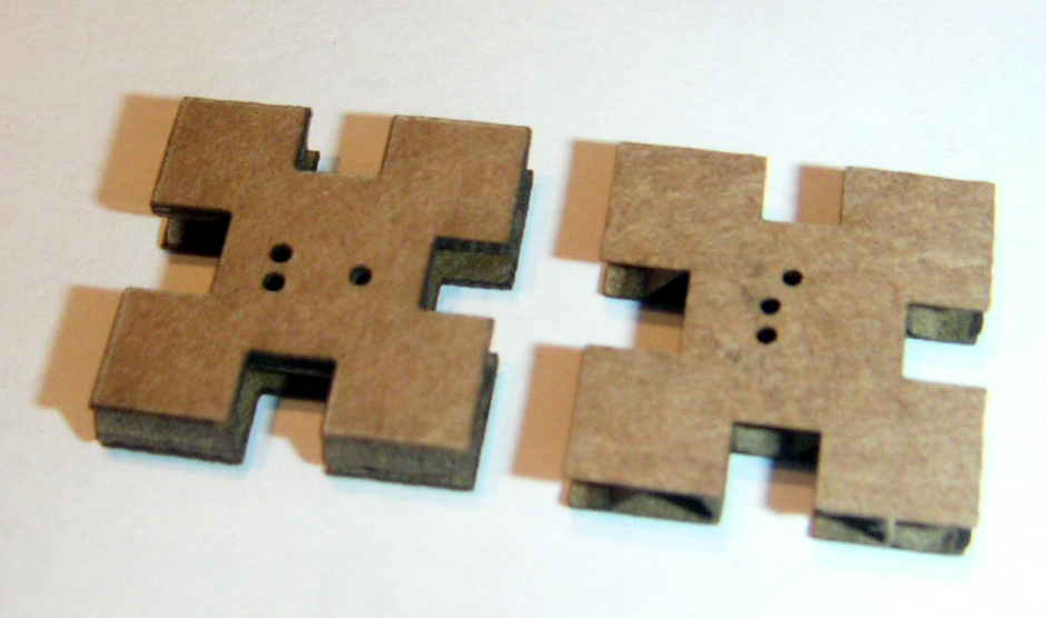
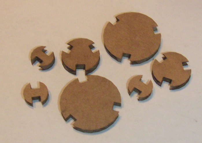

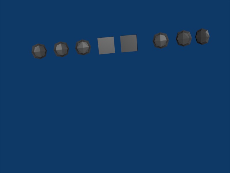
Predicting randomly assembled structures: The GIKs in the picture on the left have three types of connector bays: Normal, tight (indicated with one circle), and loose (two circles). The GIK on the left has tight and loose in the same direction, the GIK on the right has them at a 90 degree angle. The bays are designed so that loose+loose will barely be stable, and tight+tight very stable, with the other combinations in between. The ration of parts in a random assembly process will determine the likely final structures.The picture on the right shows circles of different sizes to make bi-curved surfaces.
assignment 3
use waterjet; have detailed plans about final projetc, discuss off website
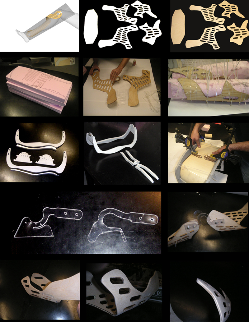
Previously, I have waterjetted a prototype of a "in-wheel suspension" design out of lexan after designing the pieces in CATIA. Now, I waterjetted aluminum support pieces for a seat project, and flextures to connect the plywood pieces that interact with the occupant. Next, I will make snap-on pieces to connect the fixtures to the plywood pieces instead of bolts.
For my final project in this class, I will make a GIK assembler. At first, it will do a one-dimensional assembly process.
One way of doing it would be to use a toy-robotic arm. It would be more interesting and challenging to make a linear actuator, using a solenoid, a spring, and a permanent magnet at first. This will be followed by more sophisticated pieces. It would be cool to make the assembler out of GIKs. This would be a test of what we can put on GIKS, how precise GIK machines can work, etc
.
This week, we learned about pcb "board stuffing" and some basics about microprogramming.
We used a pre-designed pcb board in eagle, which also allows work on schematics. The goal was to learn the basics of organizing, machining, and soldering "stuffing" a board. Adjusting the modela milling machine depth was sometimes tricky. In order to save time the coming week, I decided to make cables to connect the tiny13 chip to a parallel port for programming, and a serial port for connecting the board to run the python program. Making the serial connector was a bit diffucult, and it wouldn't last too long, I decided that a drop pf expoxy might help. The board worked in the end.
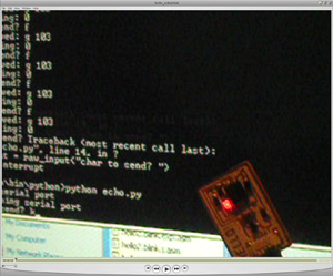
So, being experts at board stuffing, we felt ready for a bigger challenge: To design a board that would blink when it received data, and echo the input characters we'd give it. Give it "a" it will spit out "b", and so on. The problem was made easier by the fact that we had a template circuit and python scritp for both, the echo, and the blink function, we just had to combine them. This didn't poof to be entirely trivial, since assembly code has some quirks, but it was even more of a learning experience that way. Cunningly anticipating future challenges, I decided to get everything running from my windows machine. I got some tips from a previous fab class entry, and help from linux- and windows proficient class members. I had the boards working on the linux machine in the FAB area, but it would not give the correct output characters when I ran it from the cygwin console. Instead, I had to switch to the windows command line. Still, it wouldn't always give me the correct output. There might be a problem with the serial port buffer. I could get my oh-so-convenient port replicator to work, except for the parallel port. There are still lots of challenges ahead, but I'm feeling more and more that I could make almost anything... Here is the schematic, board, and movie for the echo:


I found another way of getting the correct result using the echo program without having to alter it: If I put the LED on the connection of pin8 (VCC) and the input from serial, TX (with a resistor, of course) it will light up whenever Tx pulls down pin 8 to give it an input. Also worked;).


For my basic understanding of electronics, the class "Practical Electronics" at the Edgerton Center, has been extremely useful. In order to make microprogramming easier, Jesse and I started an "Assemblicon", where we (try to) explain each line of code.
This week, the assignement was to scan and print an object in 3D. That meant egomania time: I scanned and printed my face (50% scale, of course, to save material). It worked amazingly well.

Neil had made a modification to the cam.py program so that it would interpret color intensity as depth in the z-axis. this of course lent itself to a hack: Take pictures of a face with light coming from different angles. The shadows cast would be interpreted as height and therefore translated by cam.py into 3D deformities. We could get nice 3D shapes, but we had problems getting them into correct STL files that do not contain any nonclosed surfaces. Below are the original pics (<=200x200 pixels), and 3D renderings, negatives, positives, and two Janus head pieces.

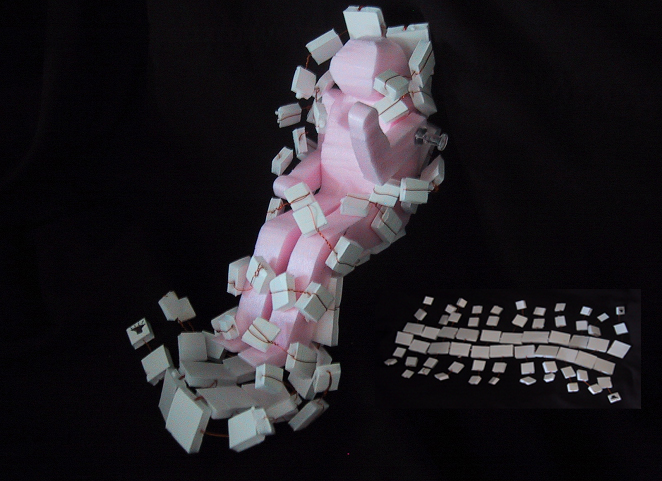
Making molds for polymer injection was the task of this week. Injection molding is a science and black art by itself. To keep things simple, we made a 2.5D mold fout of 6061 aluminum on the HAAS mill. The piece was designed as a .dxf file using a template, http://fab.cba.mit.edu/classes/863.05/classes/11_21/template.dxf, and then turned into a program for the mill using the FeatureCamm software. Theoretically, the milling machine can mill to tolerances of 1/10th mill, but for now, we were sticking to simpler to make dimensions. I tried two types of GIKs. They came out pretty well, the polymer we used was somewhat springy and elastic and therefore was quite GIKable. here is the result, GIKs at two scales:

Using Internet Zero i0 to communicate. We decided to make boards for communication by IR. We modified the i0.6. circuits and programs, and we saw packets being sent to our transmitter IR LED on the oscilloscope. But strange things happened, and after a few clicks, all our three circuit boards started to behave differently than expected. This was most likely due to the fact that we did not put an input limiting resistor in series with the LED, we only had a pullup. A pin on the tiny can typically source 10-20mAmps, 50mAmps is max. Neil also suggested we put a resistor in front of the phototransistor in order to regulate its frequency specificity.
I didn't do the project of using a very loud/ big/ visible/ obnoxious device to secretly send data using i0 (secretly because to a bystander or to an observer, the events would seem random due to variation and length of the click window), that's for another time.


