We have a one sided board, a regulator, a capacitor, a microcontroller (AT TINY 15), a header and cables for serial connection. We are going to write "hello world" using the micrcontroller and the computer screen.
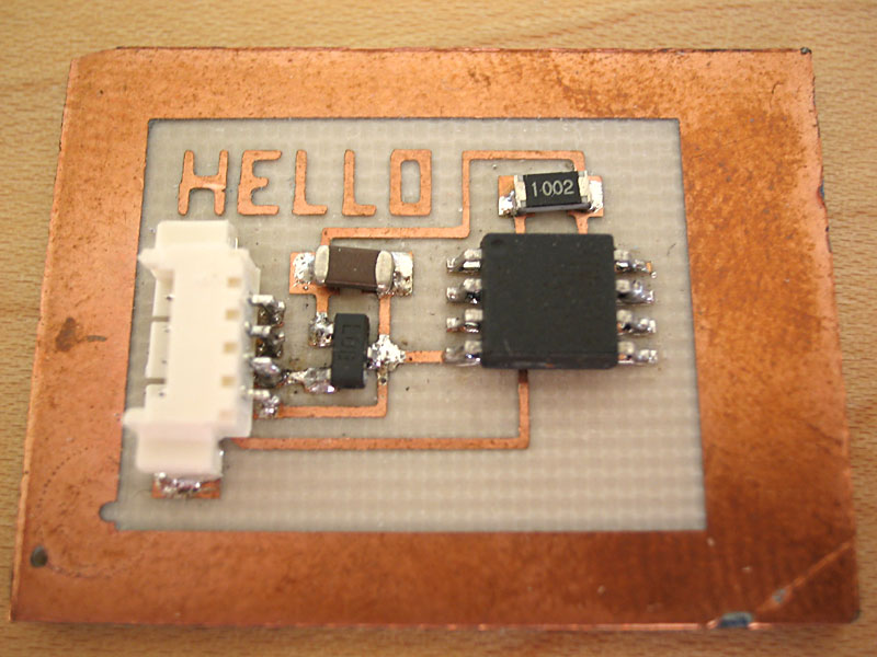 |
Circuitboard with the stuff on it. It sends "Hello World" from the serial cable. |
+ After laying out the circuitboard in Eagle, export the gerber file, and mill it using the modela. We use an already exported gerber file. To export gerber in Eagle, be sure to close the layers that you don't need to mill (you need top, pats, vias in general, not the text), then go to File > CAM Processor, select Device > GEERBER_RS274X, name the file "myfile.cmp", and finally "Process Job".
+ Solder the stuff to the layout, and check the connections with a digital voltmeter (DVM). Solder tends to go to the warmer areas, so first of all heat the place where you want to put the solder, then it will go there itself, and life will be easier. Before making the cables, sketch the pins, one can be an expert after a few breaking and re-making...
Programming environment
+ Program the microcontroller using AVRA Assembler (Win) and upload the code (hex files) with in-circuit programmer UISP (download the latest). For Windows, installing UISP and AVRA with Cygwin linux environment worked for me. Make sure you install the make, automake and gcc components (select them during the Cygwin setup). Go to UISP folder using Cygwin and type ./configure, then make, and then make install. Go to AVRA folder and type make and then make install. After the installation AVRA and UISP applications should be in usr\local\bin.
+ Download and install Python, modules pyserial, pyparallel, giveio and pywin32. You may want to install the Tkinter module - a gui toolkit, and use the inputs you've get from serial to create dynamic graphics.
+ Add avra, python and uisp directory paths to the classpath to run everything in the command line: My computer > Advanced > Environment Variables, edit CLASSPATH in System Variables, add paths seperated by semi colons - don't leave blanks. Or you can simply use windows command prompt, for example type path c:\python23;%PATH% to add the python to class path.
+ Check out the hex numbers for your parallel and serial ports. They are used in python (e.g. in rx.py) for receiving data from the microcontroller. In windows, Device manager > Ports (COM&LPT), right click > properties on the ports, go to Resources tab, it is the I/O Range - usually 0x378.
Compile the hello.asm using the avra assembler (make sure hello.asm, tn15def.inc and tn26def.inc are in the same folder), it generates "hello.hex" file. Then clip the parallel programmer head to the microcontroller and upload hello.hex using the uisp:
uisp -dlpt=0x378 -dprog=dapa -dvoltage=3 -dt_sck=50
--erase --upload if=hello.hex
+ Run the python file rx.py, it will read the serial port and write the output to the screen. Make sure you are using the correct port number. It is usually 0x378, 0x3F8 etc., you can use COM1, COM etc. as well.
For more information about AVR: AVR Freaks is a goood source.
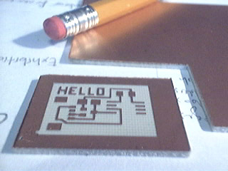 |
Milled circuitboard |
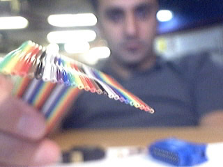 |
Cables for programming microcontroller and listening the circuit. |
 |
Making the cables and fitting them into headers. While soldering, first heat the place where you want to solder, then put the solder. Solder likes the hot places. Check the connections with a voltmeter after soldering. |
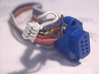 |
Serial cable is ready after 3-4 hours of soldering. |
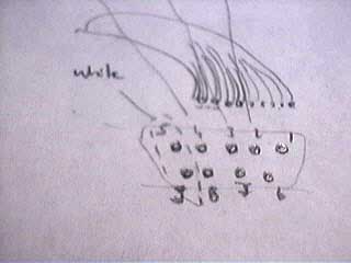 |
Sketch of pins for serial connection. |
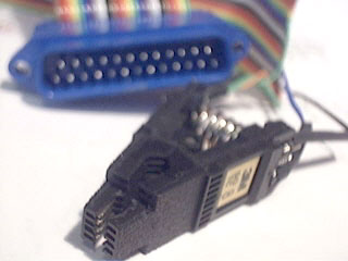 |
Parallel cable and the clip for programming microcontroller. |
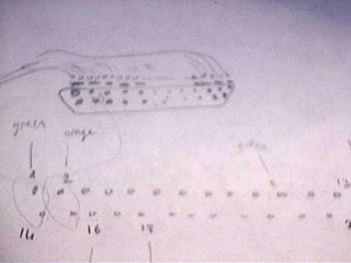 |
Sketch of pins for parallel connection. |