|
Assignment #10 11/28/2005 |
How to Make
almostAnything MAS863 | Fall 2005 |
|||
| RETURN |
Assignment: Make a 3-D construction kit & update status on the Final Project. Project:
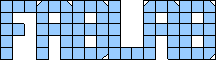
Tasks: 1. My idea was to create a GIK part from the word FABLAB. The idea was to use a block letter font to use the gaps in the word as the inter-connection joints. I was unable to find an appropriate font so I built the "FABLAB" from blocks within OpenOffice 2.0 Draw.
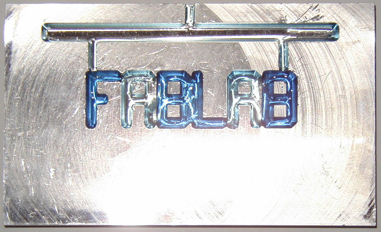
Initial file with just blocks & a few triangles...then merged most blocks 2. The HAAS would need g code which would need to be generated from FeatureCam (or cam.py if the sticking to 2d) which in turn needed a .dxf file. The file conversion was cumbersome only because I started with OO2.0: OpenOffice 2.0 draw >> OpenOffice 1.1 draw (2.0 did not agree with next 2 steps for some reason?) >> export to .svg >> Corel Draw import .svg >> export .dxf >> cleaned up in Omax Layout >> FeatureCam to generate the g code and saved to a floppy for the HAAS!! 3. Using FeatureCam ( and lots of John's help!) the cleaned up Omax file was further developed into a toolpath simulation. I planned on two depths to use both the gaps in the "A" s and the gaps in the "F" and "L" to link the pieces; this would provide additional structural dimensions when building. 4. The HAAS took about 30 minutes to cut out the mold. A small bit of filing was required between the "F" and the "A" to ensure flow of the plastic. The picture is taken with water and a bit of blue food coloring poured into the mold - the lighter blue "A"s are half as deep as the rest of the mold. The two depths are .318" and .159".
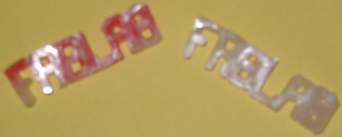
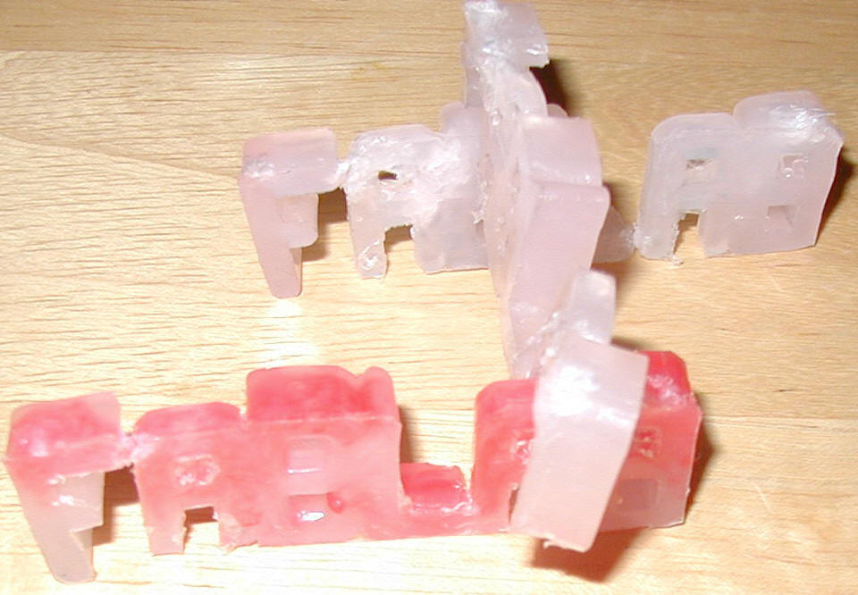
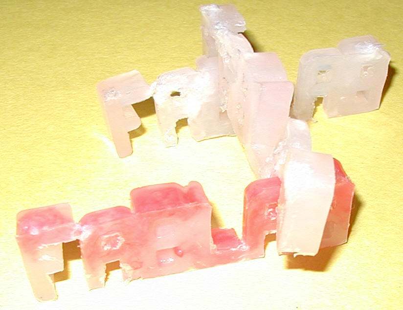
5. The next step was to inject the plastic, the machine has quite a few intricacies and techniques on getting the mold blocks in and out. Need to make sure John is handy to learn these tricks. The results are shown below. I was having problems getting the "FABLAB" out of the mold due to the straight sidewall design but mostly due to the depth of the mold; .318" was too deep - I had consulted John on this point during toolpath generation and we thought we would try it and see how it worked - I recommend .250" max without doing something to taper the sidewalls. There was quite a backlog of jobs in the lab so I managed to only produce a few pieces. Color was dependent upon whatever was in the hopper at the time it was your turn.
Final Project Update: My final project evolved rather rapidly away from my original idea (see assignment 1) with fortunate insight from Professor Gershenfeld. The idea is to work on Internet 0 forms of transmission eventually culminating in wireless forms. The following are the four phases outlined by Prof. G. to accomplish my F.P.
Tasks/progress: 1. Step0 - This past week I was able to replicate the I0 circuit using DC transmission, however it was using dated I0_6.13 boards which Professor Gershenfeld identified as quite dated (from this past summer). This was pretty straightforward in making the board and programming everything now that I have my laptop self sufficient in the ATtiny13 programming department. The difficult part is understanding the microcode and then being able to develop the next step. So Step 0 is almost there, just need to re-do using the new boards. 2. Step1 - Manu was a huge help in
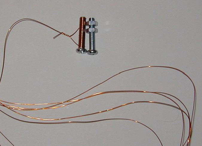
locating some coil-wire for creating my inductors. I have not made
much progress at this point since I still need to re-do the boards from
Step0. I am initially creating the coils by hand using the wire and
a bolt. 3. Panic - as given as homework - has already set in as a driving force! My emphasis for the week-end+ (Thanksgiving) is to further my proficiency at understanding the I0/ATMel code.
|
|||