|
|
|
|
|
|
|
|
|
|
|
|
|
|
|
|
|
|
|
|
|
|
|
The story in text:
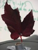
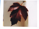
The purpose of this exercise proved to learn to take an object from our real world, transpose it onto a virtual plane, and then return it to the tangible space in which we pick things up, test them out, and show them to others. My initial thought was to do something with links because I wanted to print something with joints. I started with a horse bit and some chain as ideas, but failed to realize them and so turned to an investigation of limits: specifically, how thin can I print and still have structure, and how thin can I begin and still have a scan. I used a red maple (yes! a sugar maple, though not the standard variety as their leaves do not have enough structure to self support) leaf, but ran into trouble scanning, so I made one out of clay. Given that it is fall, and to play with color and how the device picks up lights and darks, I made half the leaf fall like and the reverse summer-esque. Once I had the scan process down, it took about twelve minutes to scan, clean the form, and save it to print. It took about twice as long to upload the files so that I could download them to the printers control station.
Making the Scans:
1. To begin, I found my object as described above. I found the machine to be pretty happy scanning in a wide range of shapes and colors. Others reported convex light images to be preferable.
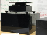
2. Once you have the object, you want to figure out how to mount it to the turntable that will enable you to get a good, clean, multi-directional scan. For the leaf, I used a piece of an old print job that had a flat base, some duct tape, and my teeth. For the clay model, I made it a large clay base from the remaining material I had brought but not used. Because I did not know too much about how sensative the scanner would be starting out, I also placed white paper on the base table, though I don't think that it was of significant benefit. The sole advantage here would have been that because there was a large, planner surface on the bottom of my scan, I could more easily brign together disparat pieces into a single form pre- merger (see below for more information on merging image).
Leaf from a Tree: I used a different process for the lead than the clay, and it did not work so I wanted to cappture that here. The process:
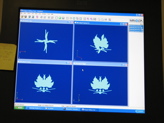
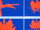
To begin, I set the leaf on the turn table, but did not calibrate using the white wedge with central axis. On this account, I ended up with four scans that are symmetrically rotated around the tables axis (as seen below). I tried to address this by selecting scans and rotating them, by adjusting alignment, and using the move command under tools, but all failed. Because the scans before merger are somewhat transparent, it proved tough to do this. The most successful alignment method, had to do with selecting three points on one scan and then lining them to three on the scan you want to converge. I used the polygon editing tool rather than GeoMagic. I assume that this caused some of my confusion. The process in images is as follows:
|
|
|
|
|
|
|
|
|
|
|
|
|
|
|
|
|
|
|
 |
|
 |
|
 |
|
|
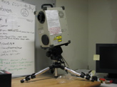
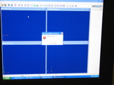
The turn table had been unplugged and so was not responding. I plugged it back in, and it worked fine. Great! |
|
|
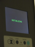
Scanner Wakes Up! |
|
Leaf is Mounted. |
|
Table Unplugged. |
|
|
|
|
|
|
 |
|
 |
|
 |
|
|
|
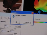
Set Rotation. (I used 90) |
|
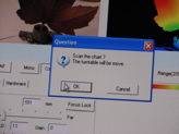
Setup the turntable. |
|
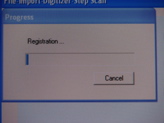
Register the scan. |
|
|
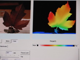
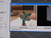
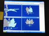
3. Once the scan is complete, it is brought into the manipulation space. Here, you have four views. The background is blue and in most modes, you can see the relevant grid lines that will direct your work. This is the point where I gave up, so beware. With greater fluidity, I would have been able to continue, but no such luck. In this case, the reason I reached a failure point was that the calibration I had done, did not actually work. To this end, I had four very cool looking, but planar surfaces that I had significant trouble meshing nicely. |
|
|
|
|
|
|
|
|
|
|
|
|
|
|
|
|
|
|
 |
|
 |
|
 |
|
|
|
|
|
|
|
|
|
Work Space. |
|
Scans visible. |
|
Selection for Manipulation. |
|
|
|
 |
|
 |
|
 |
|
|
|
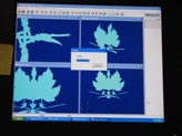
Experimental Merge. |
|
Trying to Manipulate. |
|
Leaf Doesn't Care. |
|
|
|
At this point, I gave up and I went home. Return, the next day:
CLAY!
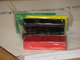
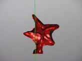
3. Upon return, I was super excited to figure out the scanner. I read the manuals the night before for both GeoMagic and the Polygon Tool and was keen to get through in brilliant fashion. I began with the decision to use GeoMagic and also to change my object to a clay model (hey, this is rapid prototyping, right? What not go from a model in my hand, to a scan, to a print! This meant giving up my linking criterion, but I assumed that I could come back to the machine once I had figured everything out and print a new file.)
4. I used soft modelling clay, which worked out great. It is soft enough that you don't have to warm it up as long as you need for femo or other more expensive clays, and is stiff enough to hold its own weight in most cases. I left blue at home so I had green, yello, red, black and grey, each block being about .2 x 2 x 2.5 inches. I modeled a very quick leaf with enlarged veins that proved significantly smaller in number than in my initial case. I made one side orange and one green to give the leaf extra structure for scanning, to enable easier line up in case I ran into more problems getting my four different scan views to line up, and to honor the shift from summer to fall, and nearly winter.
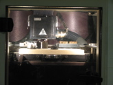
5. Turn on the scanner once you have your model. The switch in on the back, which is a little bit deceptive. Remove the two lense caps. The scanner will warm up in a few minutes.
6. Open Geomagic and click on the small blue circle on the menu bar. This will open up the import command, and alow you to begin prep for scan.
7. Place the white panel on the turntable and put its little feet into the traces on the surface. You should have the black bar facing the scanner's face. Use the nobs to adjust the view so that the image is in the window.
8. On the menu panel, select milti-step scan, set the focus to manual and play with it in the view, close the view window and change the scan angle increment to 90 degrees. Once you are happy, you are ready to click 'scan'.
9. Once you begin scanning, do not click on the gid space with your mouse. After each scan finished, click 'NEXT' to move to the next image. You will see your creation on the screen. Good job! If you have an error that suggests the scanner cannot focus, open the view window and ask it to update range and color image. This should fix your problem.
10. With the image showing it's glorious 3D self, go to tools and select merge. Once the images are merged, clean the surface and then next look over your object and remove extranious points by selecting and deleting.
11. Last, fill the holes. This should be a quick enough step, but will depend upon how many holes you have. Save as a .wrl version 2 file in order to print it. |
|
|