Jay Silver's Fab Page
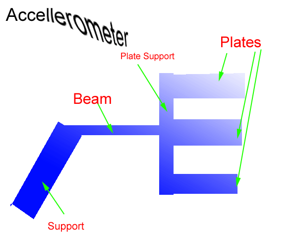
Final ProjectUrban HarvestometerI made the video by taking a screen capture of a scratch project. You can download the actual scratch project here. The scratch project will run simulations by randomly sending the dumptruck to empty the trash on a given day with a 50% chance. The sensor will record the days on which the trash is picked up. When the sensor is retrieved the following week by the urban harvesters they can read the collection times so that next week they can maximize their gathering. You can consider this simulation to be a description of what my sensor will do. I drew and fabbed an initial circuit board that will serve as a first iteration for my dumptruck sensor. 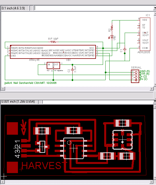 I built the circuitin the diagram and there's a picture of it below. 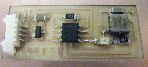 and tested the oscilloscope independent of the rest of the circuit on the oscilloscope. Here's a video showing the result: A funny thing happened - I couldn't program the microcontroller. I isolated the accelerometer, capacitor, led, and resistor from the microcontroller and then it programmed. So I systematically connected and disconnected each trace that connects the accelerometer/led to the microcontroller in every permutation. It turns out that the trace which leads to pin 7 on the microcontroller was the one causing the problem. Pin 7 is also the programming clock input, which does NOT like to be connected to a circuit with a capacitor in it because it smooths out the clock edges making programming impossible. I jumped over and rerouted the output of the accellerometer to pin 2 of the microcontroller which isn't used in programming. In the next iteration of the board I'll incorporate this structural change. I'm using a one dimensional accelerometer to detect a dumpster emptying event. The accelerometer constanly outputs a voltage of 2.5 volts if there is no disturbance. When an acceleration is detected the sensor deflects the voltage in the direction that acceleration occured to between 0 and 5 volts. A threshold will be experimentally determined and measured in terms of absolute value of deflection minus 2.5. When that threshold is crossed a timestamp will be recorded and/or an LED will get flipped on for the corresponding day. If LEDs are used it's possible that they will only get flipped on when a button is pushed so as to save batteries. I will mostly use standard components. I already have 3 accelerometers. I hope to also use some output devices probably some sort of LED array or LCD screen, which we have standard, though I'd like to order some cool LED arrays. The other parts on the circuit are standard stock in our lab. I'll be camoflauging the circuit either as part of the dumpster or as something you might expect to find in the dumpster. If I make it look like part of the dumpster I'll either laser cut or waterjet cut a specialized box and paint it to look like the dumpster. If I make it look like something you might expect to find in the dumpster I'll 3d print a make food or fake trash to embed the sensor in. Right now I've already printed a couple of peaches. They aren't hollow though, so I may print some more that are. This will require material that we already have. The main questions which remain to be answered are questions of how to program the functionality of the circuit. I have already started to program the assembly code. See the code here. As I get more and more of the circuit to work I will need to expand the size of the circuit to have more LEDs and I'll need to improve the asm code to include more complex features. I'll demo the board in "fast" mode so that days seem like minutes 1/6 of minutes. Heres the stuff I may still need: final project asm code
; ; hello3.step.asm ; step response measurement ; Neil Gershenfeld CBA MIT 10/29/05 ; ; definitions ; .include "tn13def.inc" .equ ledpin = PB1; LED1green pin .equ ledpinR = PB0; LEDRed pin .equ ledpin2 = PB4; LED2green pin ;.equ chargepin = PB1 ; charging pin .equ txpin = PB2 ; serial transmit pin .def bitcnt = R16 ; bit counter .def temp = R17 ; temporary storage .def txbyte = R18 ; data byte .def uphi = R19;
.def currshaken = R20 ; up low byte .def currweek = R21 ; up hi byte .def temp1 = R22 ; .def currday = R23; .def BSMTWTFS = R24; .def temp2 = R25;
;.def currshaken = R28; ;.def currweek = R29; ;.def hithresh = R24; ;.def lothresh = R25; ; ; start of code ; .cseg .org 0 rjmp reset; Reset Handler nop;rjmp EXT_INT0; IRQ0 Handler nop;rjmp PCINT0; PCINT0 Handler nop;rjmp timeroverflow; Timer0 Overflow Handler nop;rjmp EE_RDY; EEPROM Ready Handler nop;rjmp ANA_COMP; Analog Comparator Handler nop;rjmp TIM0_COMPA; Timer0 CompareA Handler nop;rjmp TIM0_COMPB; Timer0 CompareB Handler rjmp WATCHDOG; Watchdog Interrupt Handle nop;rjmp ADC; ADC Conversion Handler ;
;blink_led_monday: ; dec currday
;rjmp tue_blink
;output_week: ; mon_blink: ; ldi currday, 1 ; mov temp, BSMTWTFS ; andi temp, 0b01000000 ; brne blink_led_monday ; tue_blink:
blink_gre: rcall onLed1 ret
;uphi used as a temp variable check_sun: mov uphi, BSMTWTFS andi uphi, 0b01000000 breq blink_gre rcall onLedR ret check_mon: mov uphi, BSMTWTFS andi uphi, 0b00100000 breq blink_gre rcall onLedR ret check_tue: mov uphi, BSMTWTFS andi uphi, 0b00010000 breq blink_gre rcall onLedR ret check_wed: mov uphi, BSMTWTFS andi uphi, 0b00001000 breq blink_gre rcall onLedR ret check_thu: mov uphi, BSMTWTFS andi uphi, 0b00000100 breq blink_gre rcall onLedR ret check_fri: mov uphi, BSMTWTFS andi uphi, 0b00000010 breq blink_gre rcall onLedR ret check_sat: mov uphi, BSMTWTFS andi uphi, 0b00000001 breq blink_gre rcall onLedR ret
output_forever: rcall check_sun rcall check_mon rcall check_tue rcall check_wed rcall check_thu rcall check_fri rcall check_sat rcall long_print_delay rcall long_print_delay rcall long_print_delay rcall long_print_delay rcall long_print_delay rjmp output_forever
newWeek: ldi txbyte, 102 ; rcall putchar ldi currday, 0 inc currweek ;rcall output_week rcall output_forever rjmp back_to_watchdog2
sunday: ldi txbyte, 200 ; rcall putchar ori BSMTWTFS, 0b01000000 rjmp back_to_watchdog monday: ori BSMTWTFS, 0b00100000 ldi txbyte, 201 ; rcall putchar rjmp back_to_watchdog tuesday: ori BSMTWTFS, 0b00010000 ldi txbyte, 202 ; rcall putchar rjmp back_to_watchdog wednesday: ori BSMTWTFS, 0b00001000 ldi txbyte, 203 ; rcall putchar rjmp back_to_watchdog thursday: ori BSMTWTFS, 0b00000100 ldi txbyte, 204 ; rcall putchar rjmp back_to_watchdog friday: ori BSMTWTFS, 0b00000010 ldi txbyte, 205 ; rcall putchar rjmp back_to_watchdog saturday: ori BSMTWTFS, 0b00000001 ldi txbyte, 206 ; rcall putchar rjmp back_to_watchdog
emptiedToday: ldi txbyte, 101 ; rcall putchar cpi currday, 0 breq sunday cpi currday, 1 breq monday cpi currday, 2 breq tuesday cpi currday, 3 breq wednesday cpi currday, 4 breq thursday cpi currday, 5 breq friday cpi currday, 6 breq saturday rjmp back_to_watchdog
WATCHDOG: rcall onLed2 ldi txbyte, 100 ; rcall putchar cpi currshaken, 2 brsh emptiedToday back_to_watchdog: ldi currshaken, 0 inc currday; increment the day cpi currday, 7 brsh newWeek mov txbyte, currday ; rcall putchar back_to_watchdog2: reti
; ; prints a null-terminated string ; print: print_loop: lpm mov txbyte,R0 cpi txbyte,0 breq return ;rcall putchar inc zl rjmp print_loop return: ret ; ; string to print ; print_string: .db "blink",13,10,0
; onLed1 onLed2: sbi PORTB, ledpin2; init LED pin sbi DDRB, ledpin2; ldi zl,low(print_string*2) ldi zh,high(print_string*2) cbi PORTB, ledpin2 rcall print rcall long_print_delay sbi PORTB, ledpin2 rcall long_print_delay ret
onLedR: sbi PORTB, ledpinR; init LED pin sbi DDRB, ledpinR; ldi zl,low(print_string*2) ldi zh,high(print_string*2) cbi PORTB, ledpinR rcall print rcall long_print_delay sbi PORTB, ledpinR rcall long_print_delay ret
onLed1: sbi PORTB, ledpin; init LED pin sbi DDRB, ledpin; ldi zl,low(print_string*2) ldi zh,high(print_string*2) cbi PORTB, ledpin rcall print rcall long_print_delay sbi PORTB, ledpin rcall long_print_delay ret
; ; putchar routine ; assumes no line driver (doesn't invert bits) ; .equ sb = 1 ; number of stop bits bitdelay: ldi temp, b bitloop: dec temp brne bitloop ret ; ; long_print_delay ; delay between printed lines ; .equ delay = 60 long_print_delay: ldi temp2, delay charloop2: ldi temp1, delay charloop1: ldi temp, delay charloop0: dec temp brne charloop0 dec temp1 brne charloop1 dec temp2 brne charloop2 ret
putchar: ldi bitcnt, 9+sb ; 1+8+sb com txbyte ; invert everything sec ; set start bit putchar0: brcc putchar1 ; if carry set sbi PORTB, txpin ; send a '0' rjmp putchar2 ; else putchar1: cbi PORTB, txpin ; send a '1' nop putchar2: rcall bitdelay ; one bit delay rcall bitdelay lsr txbyte ; get next bit dec bitcnt ; if not all bits sent brne putchar0 ; send next ret ; else return ; ; serial bit delay routine ; .equ b = 17 ; 9600 bps settle: ldi temp, delay settleloop: dec temp brne settleloop ret
bigShake: inc currshaken ; ldi txbyte, 103 ; ; rcall putchar mov txbyte, currshaken ; rcall putchar rcall onLedR ;rcall long_print_delay rjmp loop
; ; main program ; reset:
ldi temp, low(RAMEND) ; set stack pointer to top of RAM out SPL, temp ; ; ; init output pins ; sbi PORTB, txpin ; comm sbi DDRB, txpin ; "
ldi txbyte, 111 ; rcall putchar
; ; init A/D ; cbi ADMUX, REFS0 ; use Vcc as reference sbi ADMUX, ADLAR ; changed to left ---- (no longer) -->right-adjust result sbi ADCSRA, ADEN ; enable A/D cbi ADCSRA, ADATE ; disable auto-trigger cbi ADCSRA, ADPS2 ; set prescaler for /2 cbi ADCSRA, ADPS1 ; " cbi ADCSRA, ADPS0 ; " sbi ADMUX, MUX1 ; input on ADC1 sbi ADMUX, MUX0 ; "
; initialize number shaken and current day ldi currday, 0 ldi currshaken, 0 ldi currweek, 0 ldi BSMTWTFS, 0
mov txbyte, currday ; rcall putchar
;init watchdog timer interrupt ldi temp, 0b01100001 out WDTCR, temp
; enable interrupts in general sei
rcall onLed2 ; ; infinite main loop ;
loop:
rcall settle
sbi ADCSRA, ADSC ; start conversion adloopup: sbic ADCSRA, ADSC ; loop until complete rjmp adloopup
in uphi, ADCH ; get high byte cpi uphi, 100 brlo bigShake in uphi, ADCH ; get high byte cpi uphi, 156 brsh bigShake
rjmp loop
Final Project Board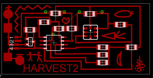 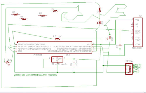 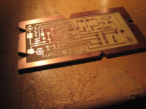 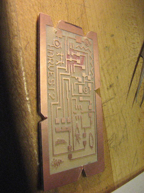 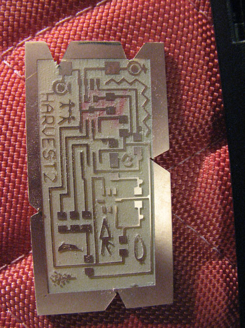   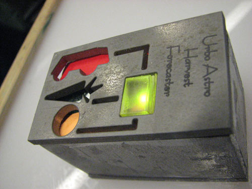 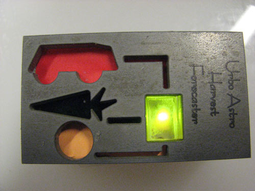  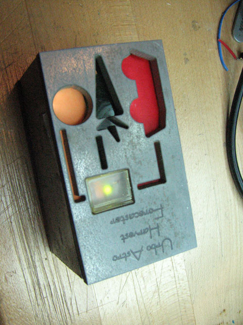 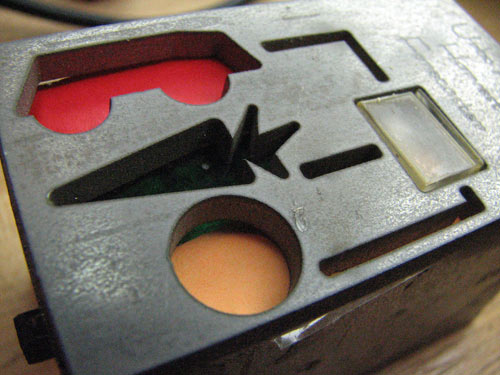 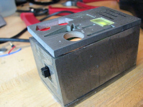 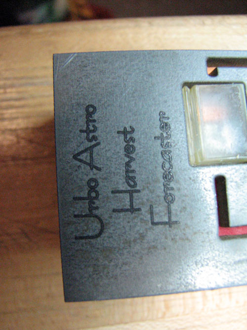 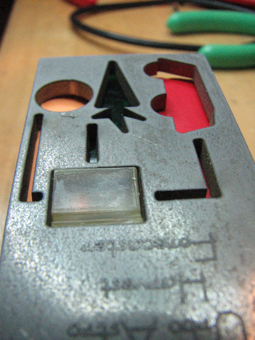 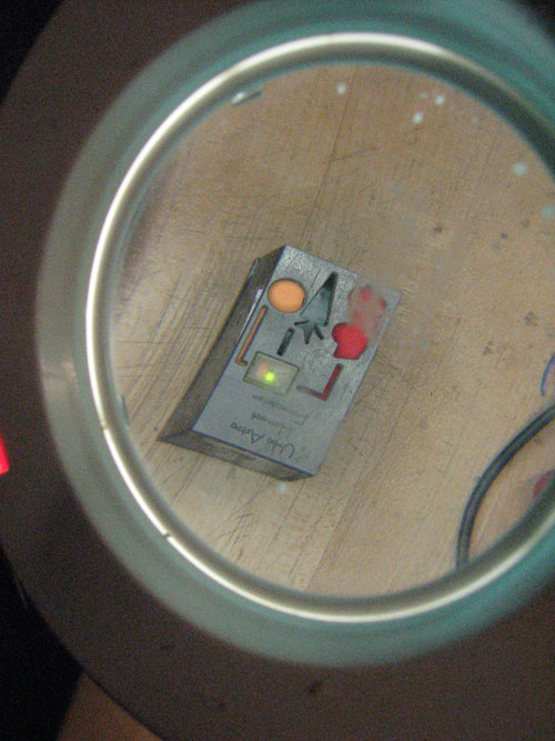        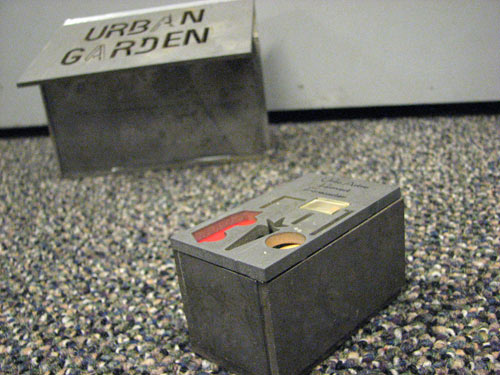 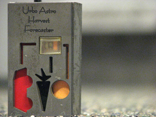 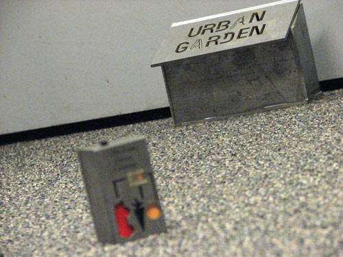 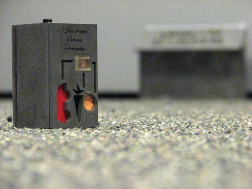 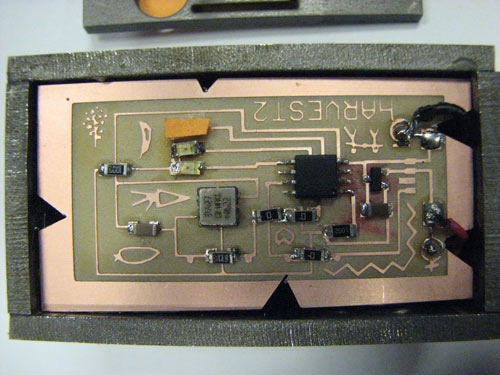 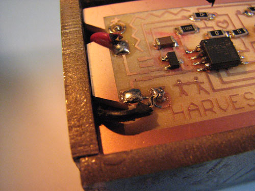 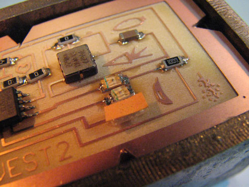 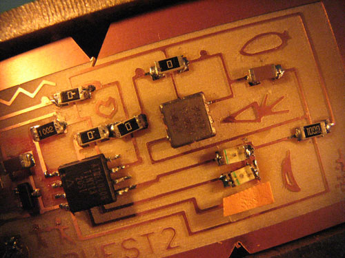 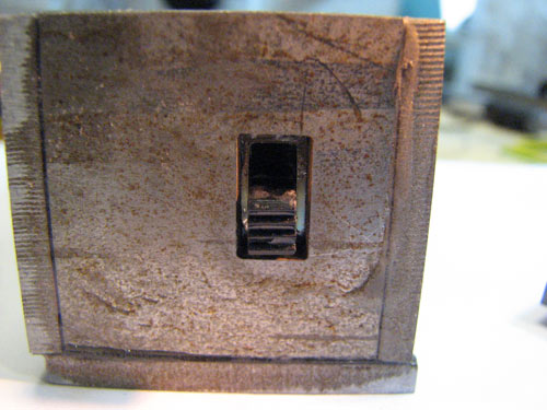 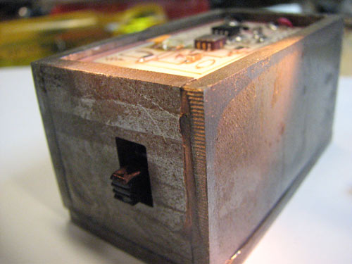  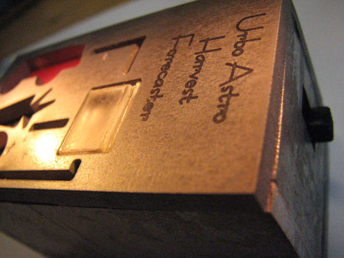 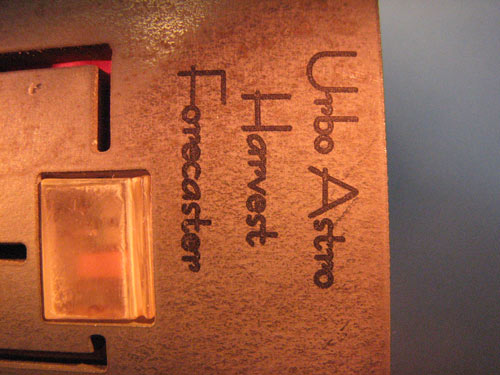 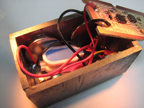 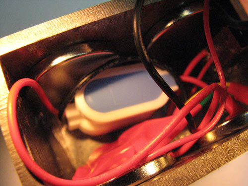 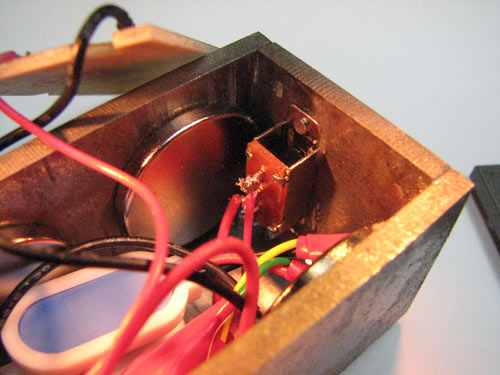 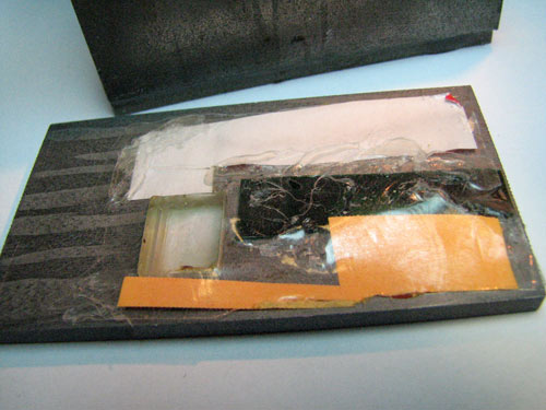 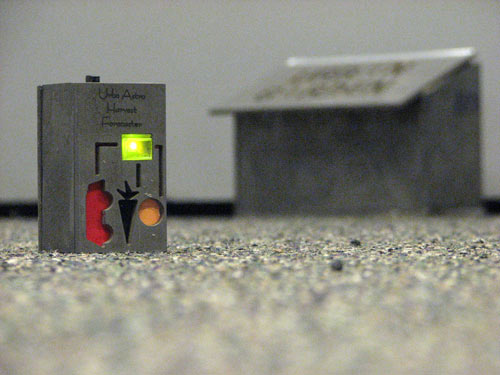 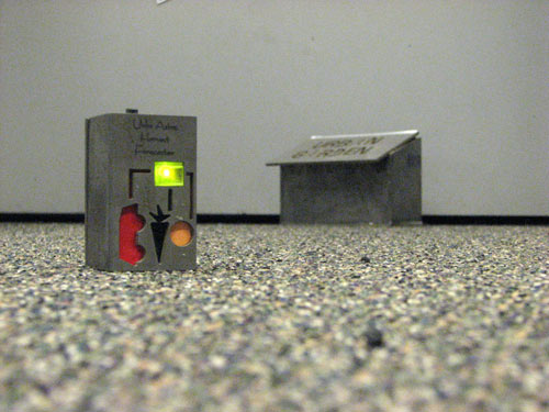 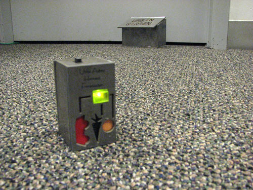   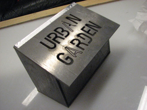  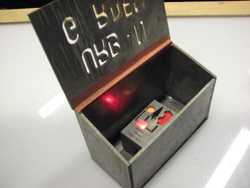 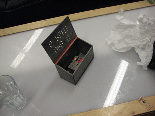  Week 1 Blender Animation
Week 2 Subtractive Devices and PressfitLaser Cutter in 5 Minutes tutorial
Pressfit building starsA one-piece building kitI attempted to build a contruction kit that uses only one piece to make anything you want. This isn't perfect but here are some things you can build with the it.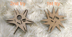 A geodescic type dome 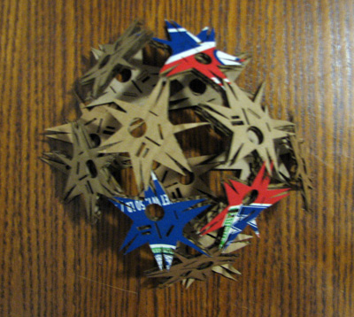 Attached to another sculpture 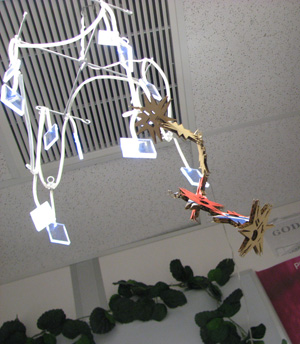 Wearable 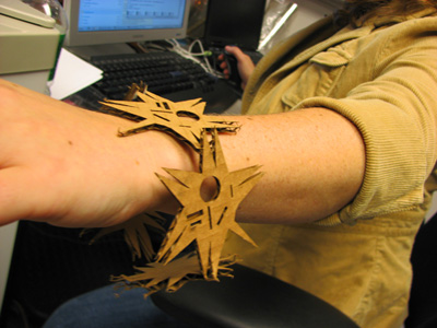 Here are the source files First Try -- Second Try PCBMikey's Guru PCB TutorialDownload (WMV 45MB)Week 4 & 5 - cables and HTM(A)AMy first chip was a soldering disaster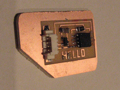 Severl chips later, I have come to a comfortable level with my soldering 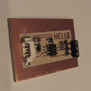 Closeup of parallel connector 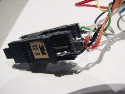 Both cables 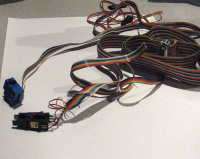 We worked on the voltmeter as a group since that's the basic tool needed to create other tools. Now that we have a working voltmeter I started to design an ohm meter. This next week I'd like to design a vibrometer. 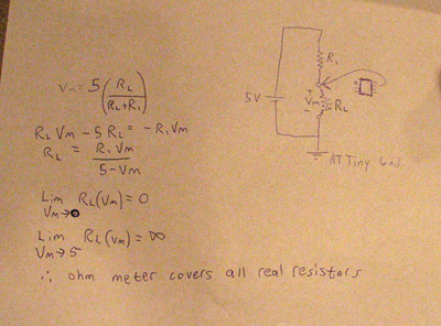 Week 6 - 3d ScanningHere is a peach I made Actually it started out as an orange. I 3d scanned it using a wide spacing and with lighting on both sides. Apparently I didn't light the bottom very well because while it looked like a shaded orange to the eye it came out as a deep red on the screen and subsequently on the zcorp printer. It's quite realistic however as a peach. Z Corp Printing TutorialI did a tutorial tutorial with Neri where I showed her how to make a tutorial from scratch. We used the Z Corp Printer as our subject. We experimented with getting the tutorial extremely short at the cost of leaving out some detail. Here is the finished movie:3D Printer Tutorial (WMV) 3D Printer Tutorial (MP4)
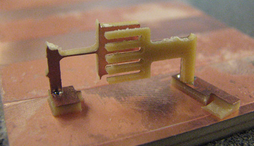
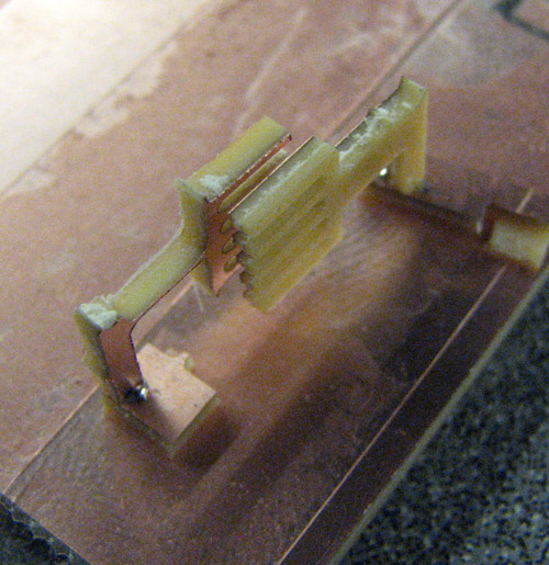
Waterjet cutterSpring Flexure for Shoe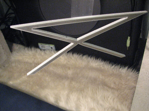 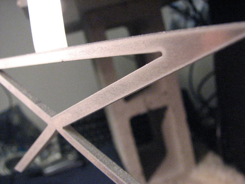 Spring Flexure on shoe 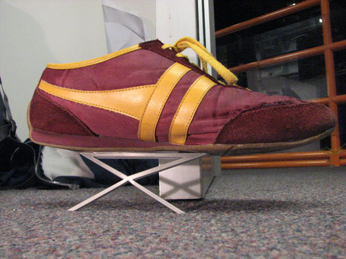 Design for nested and curved spring shoe flexure 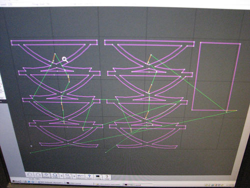
|