


This week was about making an output device that responds to something.
Servos!
I wanted to make a controller for a servo that would record the position the servo arm was moved and play it back, similar to Topobo and other projects. But I wanted to be able to modify its position AS it was running like a sequencer, instead of having a separate record and playback mode (where recording relinquishes control of the servo and simply measures potentiometer data). I considered a lot of different paths to this goal. Initially, I wanted to make my own servo control board and write a PID controller that would take into account a user backdriving the motor. Peter Schmidt pointed me to the OpenServo project, an open hardware/software servo controller that fits inside an existing servo, and also can communicate over I2C. I decided to try to make a fab-able version of this board, on a single sided board and using the components from the inventory.
There was a lot to learn...
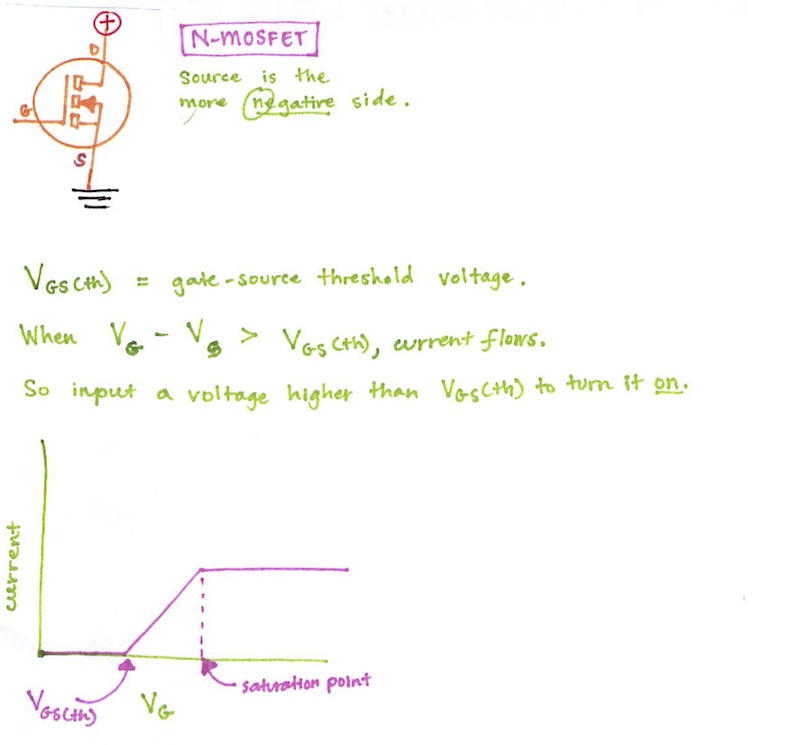
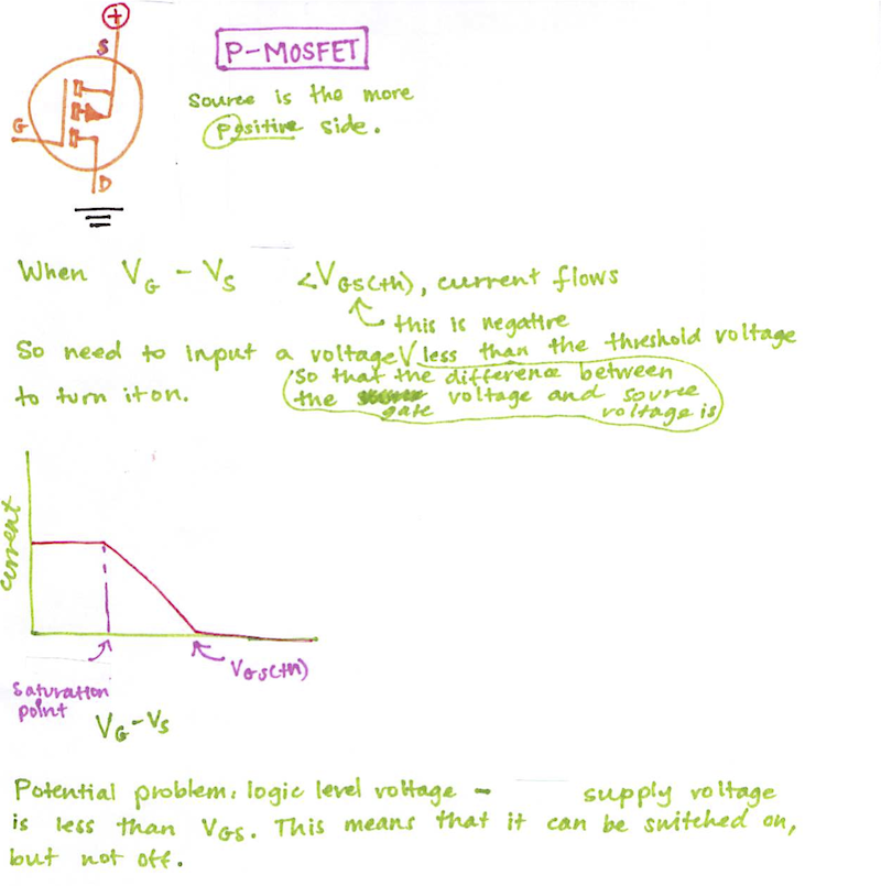
What is a MOSFET? What is an h-bridge, and why does it require two P-MOSFETs and FOUR N-MOSFETs?
Pictures had to be drawn and many questions asked more than once (thanks Brian Mayton and Ed Baafi!)
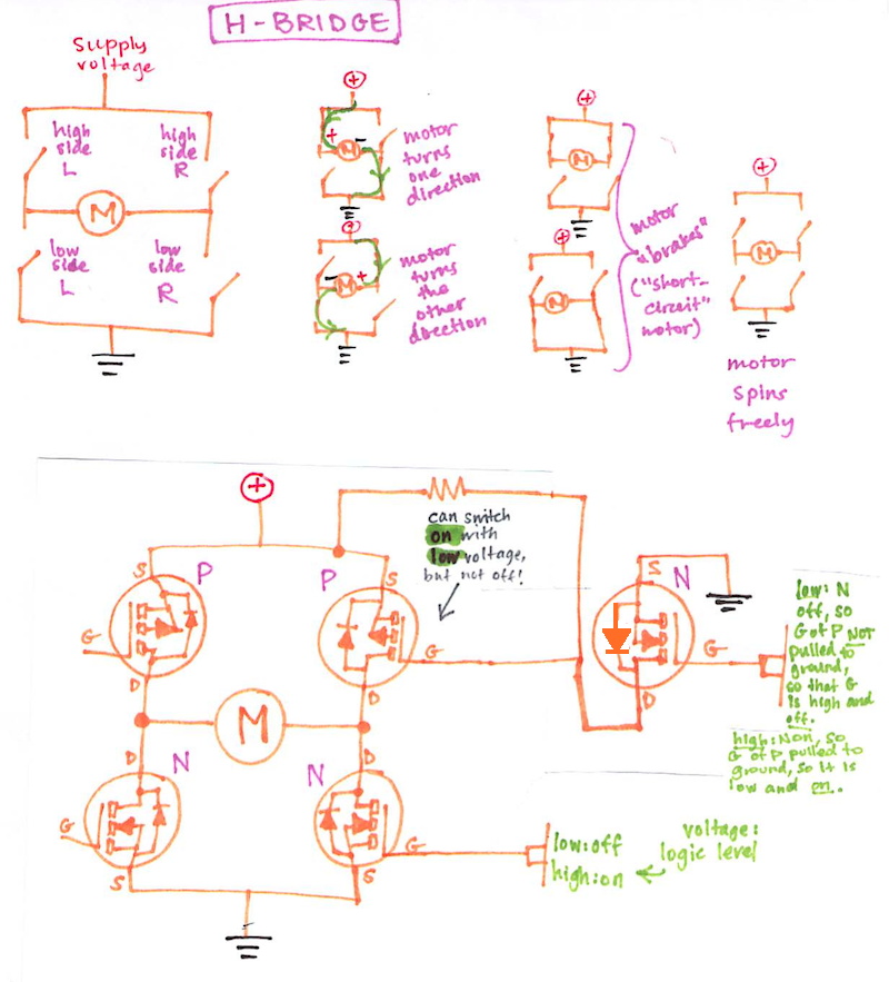
(Here are some more things I learned about motors: if you connect the leads of two motors together and move the shaft of one, the other one will spin at the same time. If you short the leads of a motor, it brakes and you can't spin it anymore.)
Once I understood that, I was able to replace the multiple components in the OpenServo design with a single h-bridge chip, and also understand that since I was powering the servo off 6V, I didn't need the extra N-mosfets.
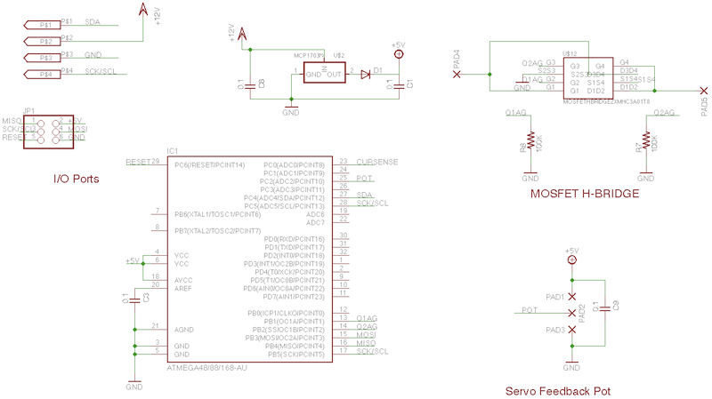
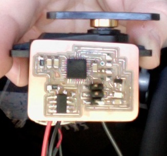
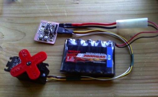
I made that board and installed it on a broken servo (I didn't quite succeed at making it small enough to fit inside), but have not tested it yet. I realized there was a more direct path to my goal. I needed an extra sensing mechanism in addition to the potentiometer inside the servo, because the potentiometer data is used by the existing PID controller to build its model. With a lot of help figuring this out (thanks Siggi Orn and Brian Mayton!), I decided to sense the current draw of the circuit to figure out if the motor was being backdriven, so that the servo could then relinquish position control to the user until the user let go.
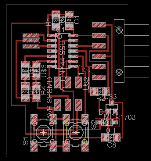
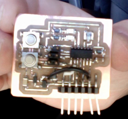
Figuring out the timing for software PWM took a long time, but I did get to learn to use an oscilloscope (thanks Adam Setapen!). The servo control is finally functioning, and I need to program in the current sensing. There are a few things I need to do in the next iteration of this board: put the servo signal on a hardware PWM pin, put the buttons on interrupt pins (they control the length of the loop), move some traces that were a little too close together and ended up shorting and breaking a connection to ground.