Week 9: INPUT DEVICES, VISUALDATA
This week for HTM(A)A, our task was to mill and program a board with a sensor, and then test it!.

I decided to mill 3 of the options..light, step response, and sound. Milling went fine, I found that the right side of the modela bed cuts better...more evenly!

Later on I decided to stick with the photo-resistor (light), and wanted to see if I could design some quick software sketches that could become info-informed sweater patterns for my final project. Stuffing went fine.
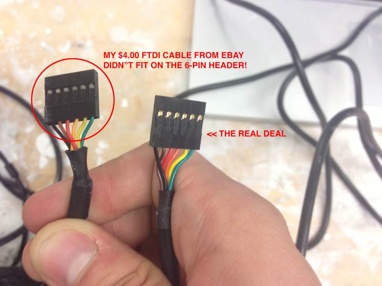
I was super excited to try my brand new FTDI cable that had come last week from ebay. Unfortunately the pins on the back wouldn't budge, and thus, my $4 went to waste. But the resemblance to the genuine is uncanny, no?
Programming went good, I followed kelly's excellent instructions on getting serial python set up on the mac. I will reiterate.
To setup Pyserial:
1. Open Terminal..
2. Type: sudo easy_install pip.
3. Type: sudo pip install pyserial.
.
To configure the USB port:
1. Type: ls /dev/tty.usb*\.
2. Hit ''Enter'' and you should get your port's name. .
3. If you don't get a port name you need to install the VCP driver from here..
.
.
To run the .py file:
1. Type: python filename.py /dev/tty.usbserial
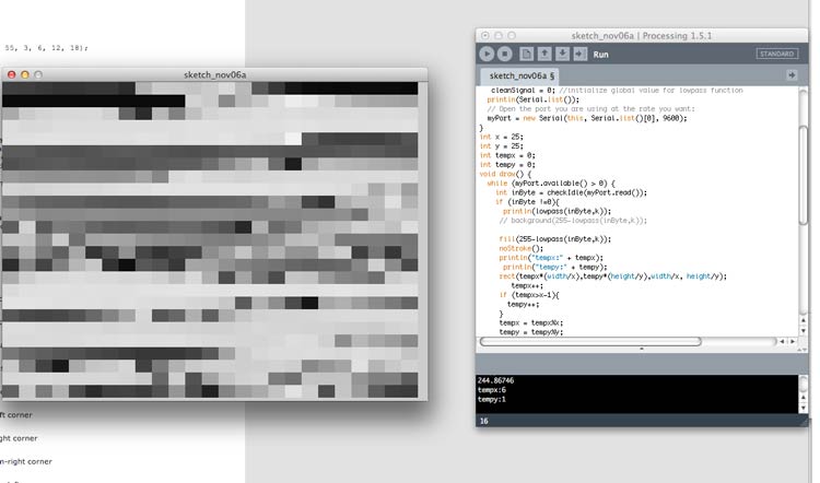
Now that I figured out how to run Neil's python gui...I wanted to take a crack at reading from the values myself..being a little familiar with processing, I used the Serial Library (very similar to arduino), to connect and read the values..I ended up making a few visual patterns..
I first saw that the serial would read 1,2,3,4,[light value],1,2,3,4..etc...so I parsed out the light value and then later on found a sensor filter (software based), which helped smoothen the light readings slightly.
I did three examples..a simple dimmer script, a growing grid of elements, and then vertical bars. All of these use the light value read from the sensor (0-255) to calculate the appropriate greyscale.
PIXEL GRID
After the basic dimmer and illuminating of the background, I wanted to get some dynamic patterns..this is an adjustable grid of grayscale pixels..each one representing the sensors reading at that given time. I used a led light from a cellphone and my hand to exaggerate.
BAR GRAPH

This is a bar graph visual that also is constantly superimposed on.
The Code is below: (Just delete the '/*' and '\*' around the example you want to test).
import processing.serial.*;

Serial myPort;  // The serial port
   float k = 0.25; //alpha level for lowpass function
      float cleanSignal; // global veriable for lowpass function

void setup() {
  size (640,480);
  // List all the available serial ports
   cleanSignal = 0; //initialize global value for lowpass function
  println(Serial.list());
  // Open the port you are using at the rate you want:
  myPort = new Serial(this, Serial.list()[0], 9600);
}
int x = 5; //this is how many divisions in x axis
int y = 5;//this is how many divisions in y axis
int tempx = 0;
int const_ = 20; //this is vertical bar thickness
int tempy = 0;
void draw() {
  while (myPort.available() > 0) {
    int inByte = checkIdle(myPort.read());
    if (inByte !=0){
      println(lowpass(inByte,k));
/*
  //background test
  background(255-lowpass(inByte,k));
  //<--end background test
*/
/*

//<--grid test
     fill(255-lowpass(inByte,k));
     noStroke();
     println("tempx:" + tempx);
      println("tempy:" + tempy);
     rect(tempx*(width/x),tempy*(height/y),width/x, height/y);
        tempx++;
     if (tempx>x-1){
       tempy++;
     }
     tempx = tempx%x;
     tempy = tempy%y;

//<--end grid test


/*
//bar test
     fill(255-lowpass(inByte,k));
    stroke(255);

     println("tempx:" + tempx);
      println("tempy:" + tempy);
         println(lowpass(inByte,k));
     rect(tempx,height,const_, (-height/255)+(-lowpass(inByte,k)));
        tempx= tempx+const_;

        tempx = tempx%(width);

  //<--end bar test
  */
}
  }

    }
int checkIdle(int val){
if (val==1 || val==2 || val==3 || val==4){
  return 0;
}
else{
  return val;
}
}

 float lowpass(float signal, float k)
      {                     //is k set globally? is cleansignal initialized globally and declared in setup?
      float oldSignal = cleanSignal;
      cleanSignal = oldSignal + (k * (signal - oldSignal));
      return cleanSignal;
      }
What to Improve
- I want to experiment with other sensors and maybe a custom board, so I can get better with electronics