Project 9 & 10: Input & Output Devices with Embedded Systems
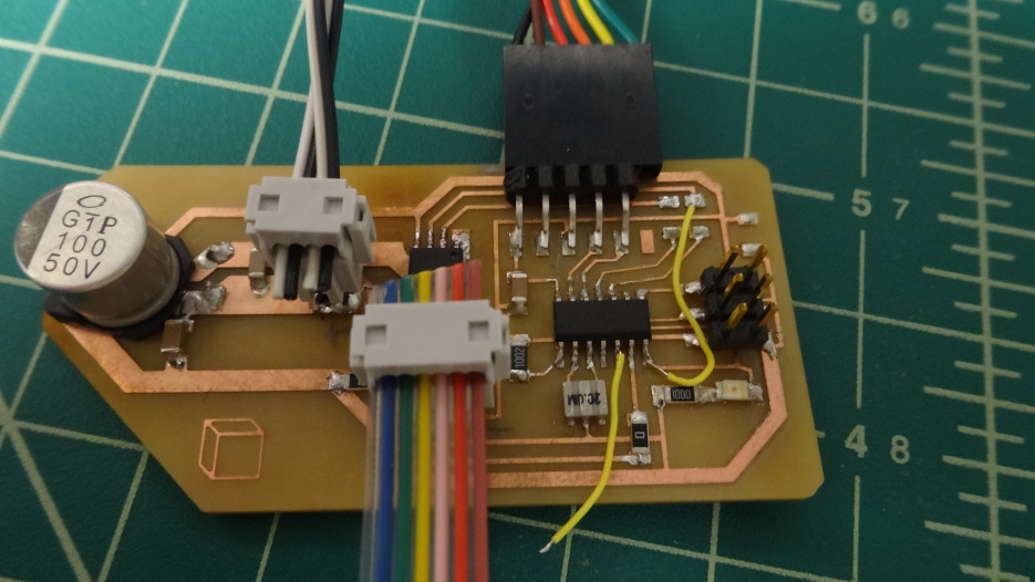
Last week I was completely slammed with research, hw, term projects, etc., so I decided to roll Input into Output devices week. So these two weeks are now combined. The object is to use a microcontroller to accept some sort of input such as an analog signal. Then use that, data somehow to make an output. Planning ahead a little bit, in week 8 I designed a board that made use of an ATTiny44 microcontroller to control an H-Bridge A4953 as well as I included some headers to send power to an output device, such as a motor and to take input from something such as a potentiometer or a capacative sensor. I also included an LED on one of the pins that is shared with the ISP header so I could have some sort of onboard diagnostic tool. That week was more about getting the board together than making use of the components. This week I got everything working.
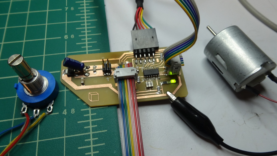
The picture above shows all of the components I wanted to use. It seemed relatively simple to me, just bring in an input then use it to drive the motor current through an h-bridge. I had programmed an 8bit PIC before and also done some bit with Arduino, but this is the first time I've played with an Atmel chip, and tried to play with avr-libc. Also, this is the first time I've played with a 10bit ADC and a 16bit PWM timer. Working with multiple bytes was a bit confusing for me at first, the most confusing part of course being that I need to read through the datasheet and try to understand what it was telling me. It's obvious to me that I just need to do this a bunch and have friendly labmates around to help answer questions to get me up to speed. This week the lovely Nadya Peek from my lab (CBA) helped me with some mental hurdles - she's a badass btw.
Let me list the issues I had:
- My PWM signal was not looking very square, but very rounded and discontinuous while using the Oscilloscope located above my desk.
- Turns out neither of the oscilloscopes located on my new desk are working correctly.
- Also, the voltage regulator I installed was ringing at about 250khz with an amplitude of 1V. This was causing some wierd things with my pwm signal.
- When I made the board I was not paying attention to which pins were actually capable of hardware timed PWM. Turns out, of course, the two pins I chose were the two that were not able to do PWM. So I needed to rework the board a little. - Future Reference: OC1A and OC1B are able to do 16bit PWM. OC0A and OC0B are the 8bit hardware timers.
- The A4953 has a cut-in voltage that must be above 8V. I spent a bunch of time troubleshooting the motor driver, which helped me find all of these other issues. At least I learned a bit more about my board.
Ultimately, I got everything working. A potentiometer is read and the value from this pot is used to adjust the PWM duty cycle, effectively changing the speed of the motor. I wanted to do this such that I can do motor control with a potentiometer as a position feedback. Granted it won't work quite this way, but it is a demonstration that I can now read in a POT signal and control a motor. Next step is to close the loop around the motor and potentiometer, and of course build some hardware for it.
The C code and the make file are in the links.
The link to the video is not working, so here it is, hopefully working.